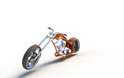
Photo Realistic Rendering
DESIGNING OF AMERICAN CHOPPER
USING SOLIDWORK
Objective:
- The objective of this project is to model the different individual parts of the American chopper using Solid works
- To assemble the different parts are designed for the chopper.
- To create a photo-realistic model of chopper and Rendering of the model Using photo view-360.
INTRODUTION:
The designing of American chopper is done using solid works application.in these first we are do the sketch and modelling the individual parts of American chopper. And after all the parts assembled with the help of solidworks assembly. After assembly rendering and photo-realistic of the American chopper with help of photo view-360.
PARTS OF THE AMERICAN CHOPPER:
The following parts of the American chopper are designed using solidworks.
- Transmission belt
- Kick stand
- Front Fender
- Rear Fender
- Chain
- Pedal
- Oil Tank
- Front Fork
- Front Wheel
- Rear Wheel
- Chassis
- Engine
- Gas tank
DESIGN TOOLS OF SOLIDWORKS:
The American chopper is designed using solid works.it consists of three environments there are.
- Part
- Drawing
- Assembly
Part:
Parts are the building blocks of the every solidworks model. Each assembly and drawing we create is made from the Part.
ASSEMBLY:
Assembly is a collection of related parts are saved in one solid work document. The components in an assembly are defined in relation to each other using assembly mates. We can attach the assembly components using various types of mates such as coincident, Concentric and distance mates etc.
DRAWINGS:
Drawings are 2-Dimensional documents that convey a design to manufacturing. And you can create the drawings from drawing templates. Within a drawing document are drawing sheets that contains drawing views.
DESIGN PROCEDURE OF CHOPPER:
-
- TRANSMISSION BELT:
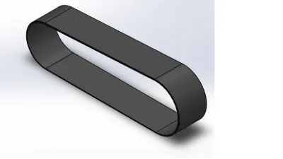
Transmissions belts are used to transmit the power from one shaft another, these belts are mostly made of Rubber materials .it requires low Maintenance and cost is also low.
-
TOOLS USED WHILE DESIGN TRANSMISSION BELT:
- Sketch
- Offset
- Extrude
- Fillet
- Appearance
Sketch:
Sketch is the 2D representation of the model with respective to the plane .in these various types of sketch options are there to create sketch. That are known as Entities in solidworks.they are like Arc. Spline, Circles,line,Rectangles.
Offset:
Offset is a one are more sketch entities. Selected model edges by specified distance.by using Offset tool we can Offset lines,arcs,Splines.
Extrude:
Extrude tool is used to convert the two-dimensional Sketch into the 3D model.
Fillet:
Fillet/Round creates a rounded internal or external face on the part. You can fillet all edges of a face, selected sets of faces, selected edges, or edge loops.
- With the help of these tools, we can design the Transmission belt of the American Chopper.
2.KICK STAND:
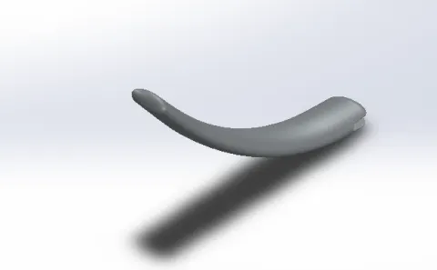
The bike rider can use the kickstand or side stand to park the motorcycle in a quick and easy manner. The side stand acts as a tripod along with the front and rear wheels, which together helps in preventing the motorcycle from falling down. Side stand is typically located on the left side of the bike, down near the rear wheel.
-
TOOLS USED WHILE DESIGNING KICK STAND:
- Sketch
- Loft
- Dome
- Extrude boss
- Extrude cut
- Fillet
- Split
- Appearance
Loft:
The loft feature in SOLIDWORKS allows you generate complex geometry in a single feature. It does this by interpolating surfaces between various cross-sections of a model. These cross-sections can be sketches, faces, or edges.
Dome:
Faces to dome. Select one or more planner or non-planner faces. We can the dome to faces whose centroid lies outside the face.
Extrude cut:
Extrude cut tool is used to remove material from the 3D model.it cuts a sketch profile while extruding.it can cut in both directions and mainly used for creating holes and slots and channels.
Split:
The split line tool is used project an entity (sketch,solid,surface,plane,etc) onto other surfaces or curved faces/planar faces. And we can able to split faces on multiple bodies with one command.
3.FRONT FENDER:
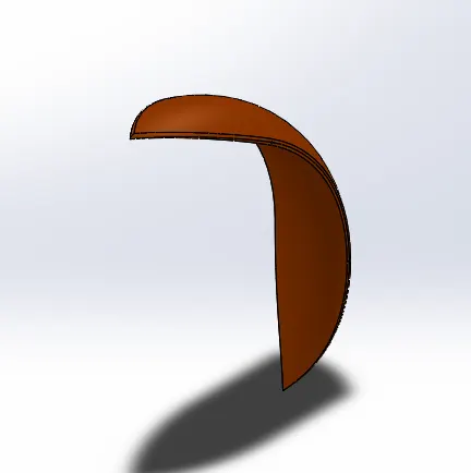
Its primary purpose is to prevent sand, mud, rocks, liquids, and other road spray from being thrown into the air by the rotating tire. Front fender is mounted on the front fork above the front wheel.
TOOLS USED WHILE DESIGNING:
- Sketch
- Offset
- Trim
- Revolve
- Dynamic mirror
- Split
- Appearance
Trim entities:
Select the trim type based on the entities you want to trim or extend. All trim types are avaliable with 2D sketches and 2D sketches on 3D planes.
Revolve:
Revolve is a method of defining three-dimensional geometry by revolving a sketched section around a centerline.
Dynamic mirror:
Select the Dynamic Mirror Entities tool to first select the entity about which to mirror, and then sketch the entities to mirror. If you want to mirror pre-existing sketch entities, select the Mirror Entities tool. We can mirror 2D sketches and 3D sketches on sketch planes.
4 REAR FENDER:
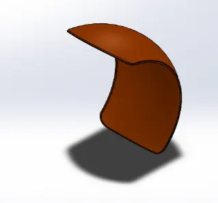
Rear fender is mounted on the chassis of the rear part above the Rear wheel.
Uses of the Rear fender is same as Front fender.
TOOLS USED WHILE DESIGNING:
- Sketch
- Offset entities
- Trim entities
- Revolve
- Appearance
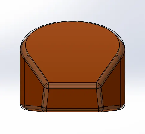
Oil tank is used to store the oil for requried to run the Engine. The oil tank is in hallow in shape. the oil tank is placed below the seat of chopper.
-
TOOLS USED WHILE DESIGNING:
- Sketch
- Boss extrude
- Combine
- Fillet
- Shell
- Appearance
Combine:
Combine is the type of tool available in solidworks to manually combine the two bodies.
Shell:
The Shell feature hollows out the inside of the solid, leaving a shell of a specified wall thickness. It lets you specify a surface or surfaces that you want to remove from the shell.
Appearance:
Appearance defines the visual properties of a model, including color and texture.appearance donot effect the physical properties, which are defined by materials.
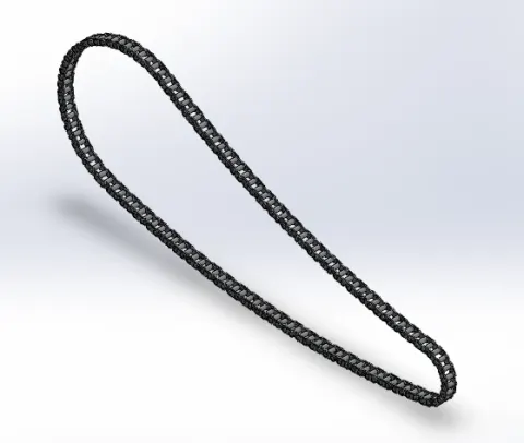
6. CHAIN:On many motorcycles, the chain connects the output shaft of the transmission to the rear wheel. It makes the rear wheel turn, which moves the motorcycle.
-
TOOLS USED WHILE DESIGNING:
- Sketch
- Boss extrude
- Circular pattern
- Fillet
- Blocks
- Pattren
- Mirror
- Appearance
Blocks:
You can make, save, edit, and insert blocks for drawing items and sketch entities that you use often, such as standard notes, title blocks, label positions, and so on. You can attach blocks to geometry or to drawing views, and you can insert them into sheet formats.
- 7.PEDAL:
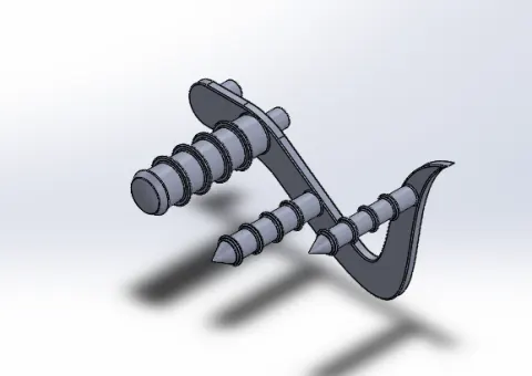
Pedals are attached to the both sides of chassis. these are used to rest feet of rider while riding the bike.
TOOLS USED WHILE DESIGNING:
- Sketch
- Revolve
- Trim
- Fillet entities
- Boss extrude
- Revolve cut
- Linear pattern
- Chamfer
- Fillet
- Cut extrude
- Dome
- Appearance
Chamfer:
The chamfer tool creates a beveled feature on selected edges, faces, or a vertex.
Dome:
Set a value for the distance by which the dome expands. Click to create a concave dome (default is convex). Control the dome feature by selecting a sketch that contains points to constrain the shape of the sketch. When you use a sketch containing points as a constraint, the Distance is disabled.
Linear pattern:
Linear patterns to create multiple instances of one or more features that you can space uniformly along one or two linear paths.
Cut extrude:
This is a handy feature to aid in material removal of a 3D model using 2D sketches.
- 8.FRONT FORK:
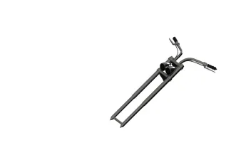
A motorcycle fork connects a motorcycle's front wheel and axle to its frame, typically via a yoke, also known as a triple clamp, which consists of an upper yoke joined to a lower yoke via a steering stem, a shaft that runs through the steering head, creating the steering axis.
-
TOOLS USED WHILE DESIGNING:
- Sketch
- Extrude
- Trim
- Revolve
- Plane
- Split
- Move
- Dome
- Mirror
- Combine
- Curve
- Sweep
- Appearance
- FRONT WHEEL:
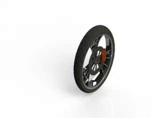
A wheel is a circular block made of the steel/alloy material. On the top of the wheel tyre is covered. The tyre is made of rubber and it has thin wires within it.
TOOLS USED WHILE DESIGNING:
- Sketch
- Revolve
- Boss extrude
- Revolve cut
- Trim
- Fillet
- Chamfer
- Linear pattern
- Cut extrude
- Circular pattern
- Appearance
- 10.REAR WHEEL:
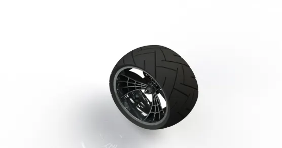
Rear wheel revolve on an axel and is fixed below a vehicle to enable it to move easily over the ground. The disc and sprocket are attached with a rear wheel. And also the chain is connected between the engine and rear wheel.
-
TOOLS USED WHELE DESIGNING:
- Sketch
- Revolve
- Boss extrude
- Revolve cut
- Trim
- Fillet
- Chamfer
- Linear pattern
- Cut extrude
- Circular pattern
- Appearan
- 11.CHASSIS:
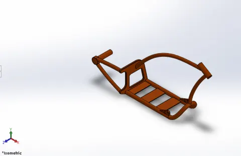
A motorcycle's chassis or frame forms its skeleton. All the components of a motorcycle, like the suspension, wheels, fuel tank, seats, handlebars etc, are attached to this base structure which lends a motorcycle its strength and ability to handle well.
TOOLS USED WHILE DESIGNING:
- Sketch
- Offset
- Convert entities
- Curve
- Plane
- Trim
- Sweep
- Cut extrude
- Fillet
- Combine
- Appearance
- 12.ENGINE:
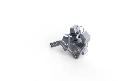
Motorcycle engines work the same way that car engine does. They consist of pistons, a cylinder block and a head, which contains the valve train. The pistons move up and down in the cylinder block, driven by explosions of a fuel-air mixture that has been ignited by a spark. Valves open and close to allow the fuel-air mixture to enter the combustion chamber. As the pistons move up and down, they turn a crankshaft, which transforms the energy from the pistons into rotary motion. The rotational force of the crankshaft is transmitted, via the transmission, to the rear wheel of the motorcycle.
TOOLS USED WHILE DESIGNING:
- Sketch
- Offset
- Convert entities
- Revolve
- Boss extrude
- Cut extrude
- Trim
- Dome
- Fillet
- Projection curve
- Composite curve
- Sweep
- Mirror
- Circular pattern
- Split
- 13.GASTANK:
Gas tank or fuel tank is used to store the fuel. It is a safe container for flammable fluids. From the fuel tank the fuel is supplied to engine whenever requried to run the engine.
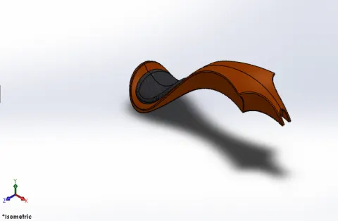
-
TOOLS USED WHILE DESIGNING:
- Sketch
- Trim
- Projective curve
- Convert entities
- Loft surface
- Sweep surface
- Surface trim
- Sweep cut
- Fillet
- Surface knit
- Appearance
Sweep surface:
Sweep is a tool that creates a solid, a cut or a surface feature by moving a profile along a path.
Surface knit:
Surface knit is used to knit the two free edges of the surfaces together. And also reduce the gap between the two edges of the surfaces.
-
ASSEMBLY OF THE AMERICAN CHOPPER:
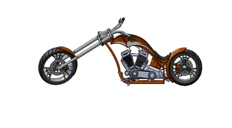
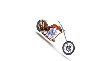
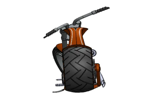
- Firstly, the Chassis part is inserted in the assembly by using insert part in the option. After the part is inserted in assembly environment click on OKto fix the Chassis.similarly other parts inserted into the assembly and also given suitable mates.
TOOLS USED WHILE DESIGNING OF CHOPPER:
- Insert part
- Mates
Mates:
Mate tool is used for joining parts in an assembly to simulate how they fit and move together.
RENDERING:
- Rendering is the process of creating realistic images of the photo realistic model with the environment.
- Rendering has been done in two categorises they are
- Firstly, the Chassis part is inserted in the assembly by using insert part in the option. After the part is inserted in assembly environment click on OKto fix the Chassis.similarly other parts inserted into the assembly and also given suitable mates.
-
-
Conclusion:
- All the parts of Americanchopper are modeled and assembled.
- Photo realistic renders were generated using photo-view 360 and solidworks visualise.