Photo Realistic Rendering
MODELLING AND RENDERING OF AMERICAN CHOPPER USING SOLID WORKS
OBJECTIVE: -
- The main objective is to create solid modelling of different parts in American Chopper.
- How to assemble different parts of the chopper.
- Creating a rendered image using Photo View 360.
INTRODUCTION: -
American Chopper is an American reality television series that airs on Discovery Channel, produced by pilgrims Films & Television. The series centers on Paul Teutal S., and his son Pal Teutal Jr., who manufactured custom chopper-motor cycles.
SOLIDWORKS: -version used for creating AMERICAN CHOPPER: -
- Solid works 2019
- Photo view360
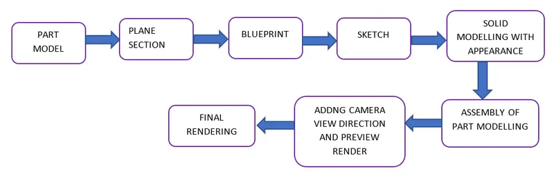
TOOLS AND FEATURES: -
CHASSIS: -
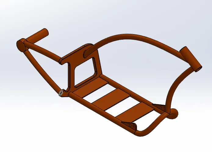
SKETCH
Sketch is a two-dimensional representation for converting 2D to 3D modeling solid works, there are different sketch and these are known as sketch entities: -Line, Circle,spline,Rectanguar and Arc.
EXTRUDE BOSS/BASS
This feature is to convert 2D into solid modelling only when the 2D sketch is completely closed. It allows to extrude the surface in both directions and also offset it to require distance.
FILLETS
This is to create curve on the profile edges on solid model by selecting the required lines or faces. This fillet has a feature to select multiple lines which reduce time consumption.
EXTTRUDE CUT
It is used to remove materials from a solid model in desired patters and also it can be extruded with both directions.
SPLIT TOOL
This tool is very handy, when two or more sloid body intersect in between or intersect each other then split tool allows to delete unwanted solid body formation and gives a clean look.
TRIM ENTITIES
There are two entities:
- Extend Entities: - which allows the broken lines to intersect each other and this can be done only in 2D sketch.
- Trim Entities: - this helps to remove unwanted extended line with the intersecting.
SWEPT SURFACE
Surface generated from section curve positioned along the path
CHAMFER
It is similar to the fillet but in chamfer, it cuts the solid model intersection area into recurred length and angle.
DYNAMIC MIRROR
This makes the solid body identical to each other this feature is used.
COMBINE
Combine feature is used to combine two or more bodies when intersecting to each other and make it is single body
ENGINE
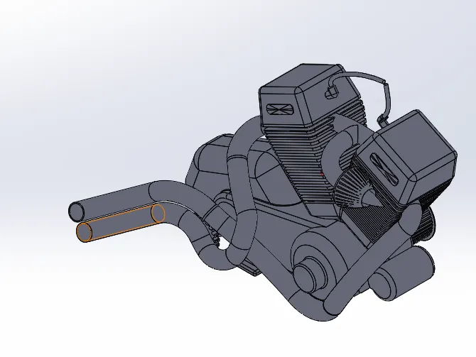
SKETCH
Sketch is a two dimensional representation for converting 2D sketch to 3D modeling solid works there are different sketch option to create a sketch and these are known as sketch entities: -Line,Circle,Spline,Rectangle and Arc
FILLETS
This is to create curve on the profile edges on solid model by selecting the required lines or faces. This fillet has a feature to select multiple lines which reduce time consumption.
REVOLVED BOSS / EXTRUDED
Create a sketch with a center line, a plane or a axis for revolve.
EXTRUDE CUT
It is used to remove materials from a solid model in desired patterns and also it can be extruded with both directions.
COMBINE
Combine feature is used to combine two or more bodies when intersecting to each other and make it as single body.
SWEPT SURFACE
Surface generated from section curve positioned along the path.
COMPOSITIVE CURVE
When the two-curve profile are broken this composite curve helps to join and make it a complete smooth single curve.
SPLIT TOOL
This tool is very handy, when two or more sloid body intersect in between or intersect each other than split tool allows to delete unwanted solid body formation and gives a clean look.
CIRCULAR PATTERN
Feature is used to create a different number of patterns required to create the circular pattern.
PEDAL
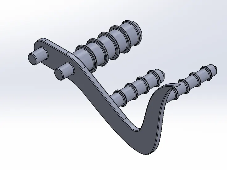
EXTRUDE BOSS/BASS
This feature is to convert 2D into solid modelling only when the 2D sketch is completely closed. It allows to extrude the surface in both directions and also offset it to require distance.
FILTTER
This is to create a curved surface on the profile edges on the solid model by selecting the required lines or the face. This fillet also has a feature to select multiple lines which reduces time consumption.
CHAMFER
It is like the fillet feature but in chamfer, it cuts the solid model intersection area into recurred length and angle.
REVOVLE BOSS/EXTRUDED
Create a sketch with a center line, a planar or an axis for revolve.
DOME
This tool provides a smooth curve on the face of the profile.
LINEAR PATTERN
Feature is used to create a different number of patterns required to create the linear pattern.
TRANSMISSION BELT: -
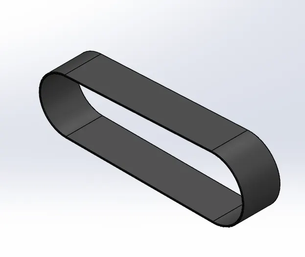
EXTRUDE BOSS/BASS
This feature is to convert 2D into a solid modelling only when the 2D sketch is completely closed.
It allows to extrude the surface in both directions and also offset it to required distance.
FILLETS
This is to create curve on the profile edges on solid model by selecting the required lines or faces. This fillet has a feature to select multiple lines which reduce time consumption.
REAR FENDER
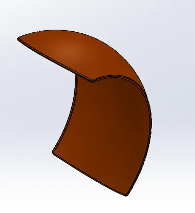
REVOLVED BOSS/EXTRUDED
Create a sketch with a center line, a plane or an axis for revolve.
SPLIT TOOL
This tool is very handy, when two or more solid body intersect in between or insect each other than split tool allows to delete unwanted solid body formation and gives a clean look.
FILLET
This is to create a curved surface on the profile edges on the solid model by selecting the required lines or the face. This fillet also has a feature to select multiple lines which reduces time consumption.
SHELL
It is used to create thickness of the profile.
REAR WHEEL
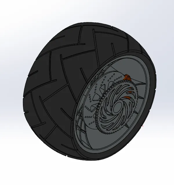
REVOLVED BOSS/EXTRUDED
Create a sketch with a centerline, a plane, or an axis for revolve.
EXTRUDE BOSS/BASS
This feature is to convert 2D into a solid modelling only when the 2D sketch is completely closed.
It also allows to extrude the surface in both direction and also offset it to require distance.
EXTRUDE CUT
It is used to remove materials from a solid model in desired patterns and also it can be extruded in both directions.
CIRCULAR PATTERN
Feature is used to create a different number of patterns required to create the circular pattern.
COMBINE
Combine feature is used to combine two or more bodies when intersecting to each other and make it single body
FILLETS
This is to create a curve surface on the profile edges on the solid model by selecting the required lines or face. This Fillet also has a feature to select multiple lines which reduces time consumption.
CHAMFER
It is like the fillet feature but in chamfer, it cuts the solid model intersection area into recurred length and angle.
FRONT FENDER
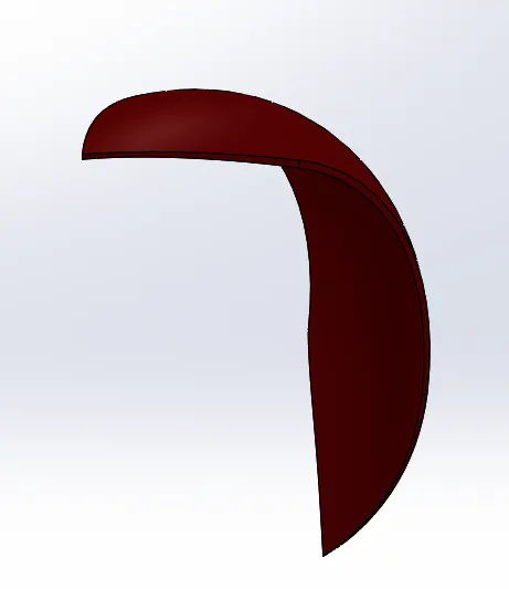
REVOLVED BOSS/EXTRUDED
Create a sketch with a centerline, a plane, or an axis for revolve.
SPLIT TOOL
This tool is very handy, when two or more solid body intersect in between or insect each other than split tool allows to delete unwanted solid body formation and gives a clean look.
FILLETS
This is to create a curved surface on the profile edges on the solid model by selecting the required lines or face. This fillet also has a feature to select multiple lines which reduces time consumption.
FRONT WHEEL
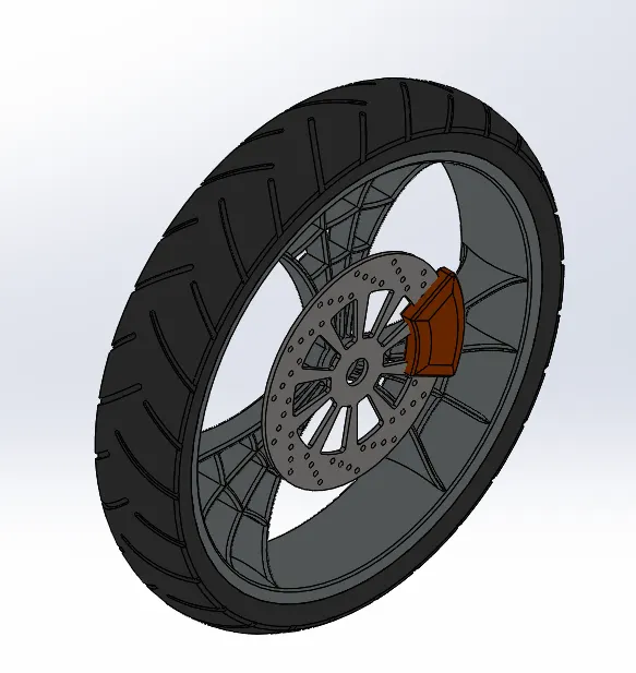
REVOLVED BOSS/BASS
This feature is to convert 2D into a solid modelling only when the 2D sketch is completely closed.it also allows to extrude the surface in both directions and also offset it to require distance.
EXTRUDE CUT
It is used to remove materials from a solid model in desired patterns and also it can be extruded in both directions.
CIRCULAR PATTERN
Feature is used to create a different number of patterns required to create the circular pattern.
COMBINE
Combine feature is used to combine two or more bodies when intersecting to each other and make it a single body.
FILLET
This is to create a curved surface on the profile edges on the solid model by selecting the required lines or the face. This fillet also has a feature to select multiple lines which reduces time consumption.
CHAMFER
It is like the fillet feature but in chamfer, it cuts the solid model intersection area into recurred length and angle.
FRONT FORK
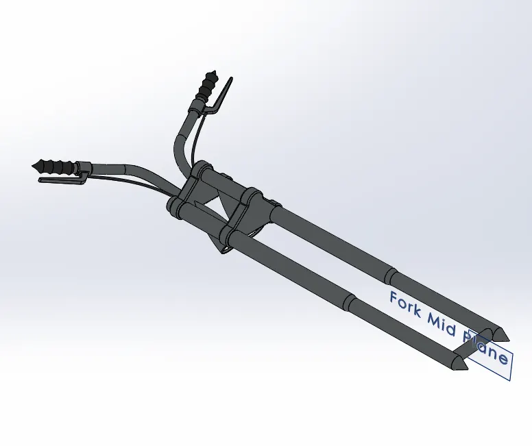
REVOLVED BOSS/EXTRUDED
Create sketch with a centerline, a plane, or an axis for revolve.
EXTRUDE BOSS/BASS
This feature is to convert 2D into a solid modelling only when the 2D sketch is completely closed.
It also allows to extrude the surface in both direction and also offset it to require distance.
FILLET
This is to create a curved surface on the profile edges on the solid model by selecting the required lines or the face. This fillet also has a feature to select multiple lines which reduces time consumption.
LINEAR PATTERN
Feature is used to create a different number of patterns required to create the linear pattern.
EXTRUDE CUT
It is used to remove materials from a solid model in desired patterns and also it can be extruded in both directions.
DOME
This tool provides a smooth curve on the face of the profile.
SWEPT SURFACE
Surface generated from section curve positioned along the path.
COMPOSITE CURVE
When the two-curve profile are broken this composite curve helps to join and make it a complete smooth single curve.
DYNAMIC MIRROR
To make the solid body identical to each other this feature is used
COMBINE
Combine feature is used to combine two or more bodies when intersecting to each other and make it a single body
KICK STAND
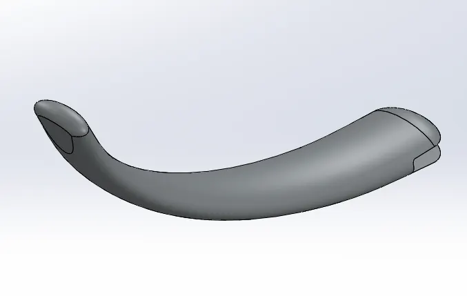
LOFTED SURFACE
Surface generated by existing edges creating a smooth tangent between the selected curves.
DOME
This tool provides a smooth curve on the face of the profile
EXTRUDE CUT
It is used to remove the material from solid model in desired pattern and also it can be extruded in both directions.
SPLIT TOOL
This tool is very handy, when two or more solid body intersect in between or insect each other than split tool allows to delete unwanted solid body formation and gives a clean look.
EXTRUDE BOSS/BASS
This feature is to convert 2D into a solid modelling only when the 2D sketch is completely closed.
It also allows to extrude the surface in both direction and also offset it to require distance.
FILLET
This is to create a curved surface on the profile edges on the solid model by selecting the required lines or the face. This fillet also has a feature to select multiple lines which reduces time consumption
OIL TANK:
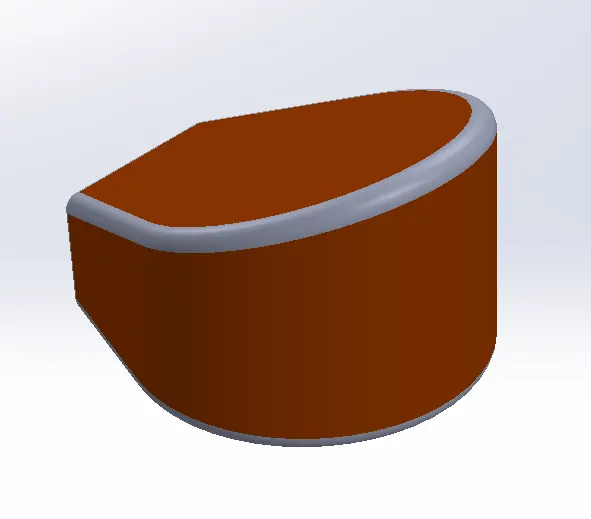
EXTRUDE BOSS/BASS
This feature is to convert 2D into a solid modelling only when the 2D sketch is completely closed.
It also allows to extrude the surface in both direction and also offset it to require distance.
COMBINE
Combine feature is used to combine two or more bodies when intersecting to each other and make it a single body
FILLET
This is to create a curved surface on the profile edges on the solid model by selecting the required lines or the face. This fillet also has a feature to select multiple lines which reduces time consumption
SHELL
It is used to create thickness of the profile.
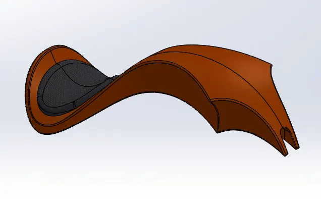
FUEL TANK
SWEEP SURFACE
These sweeps are generated from a selection of curves that are positioned along the path.
SURFACE KNIT
Which create one single solid surface body from multiple solid surface body.
COMPOSITE CURVE
When the two-curve profile are broken this composite curve helps to join and make it a complete smooth single curve.
SURFACE LOFT
This feature is used to fill the gap between the two curved surfaces
DYNAMIC MIRROR
To make the solid body identical to each other this feature is used.
FILLET
This is to create a curved surface on the profile edges on the solid model by selecting the required lines or the face. This fillet also has a feature to select multiple lines which reduces time consumption
SHELL
It is used to create thickness of the profile.
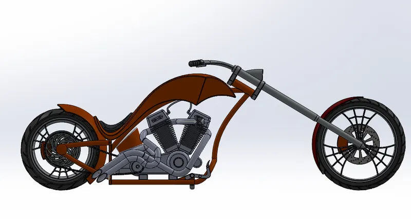
FRONT VIEW
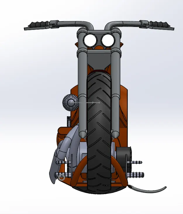
RIGHT VIEW
SIDE VIEW
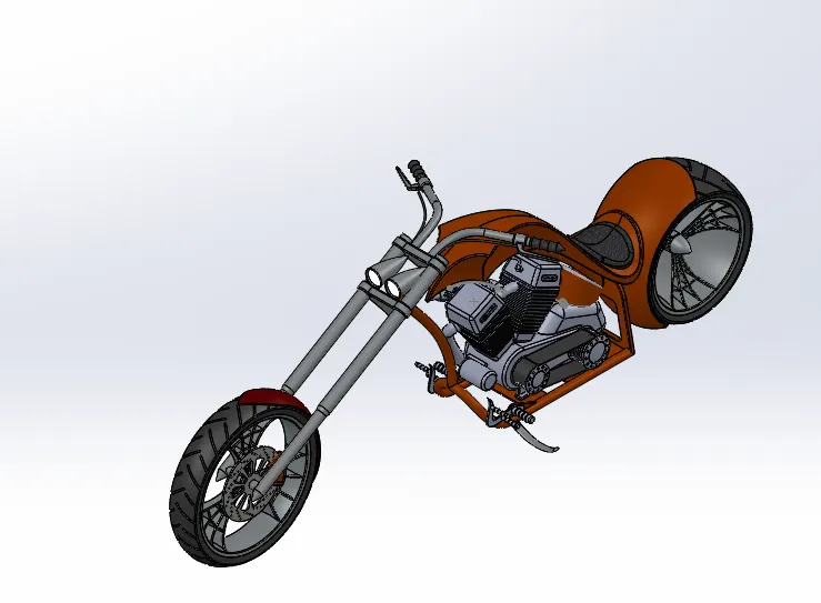
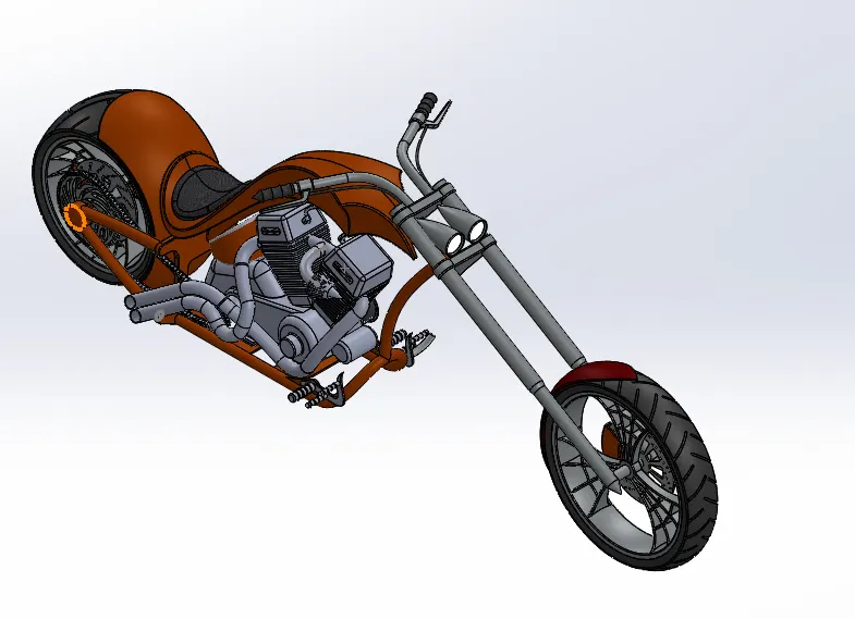
ISOMETRIC VIEW
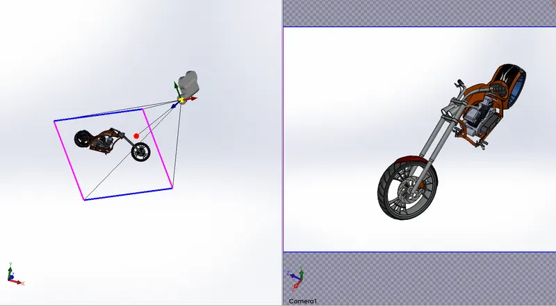
CAMERA SET UP VIEW
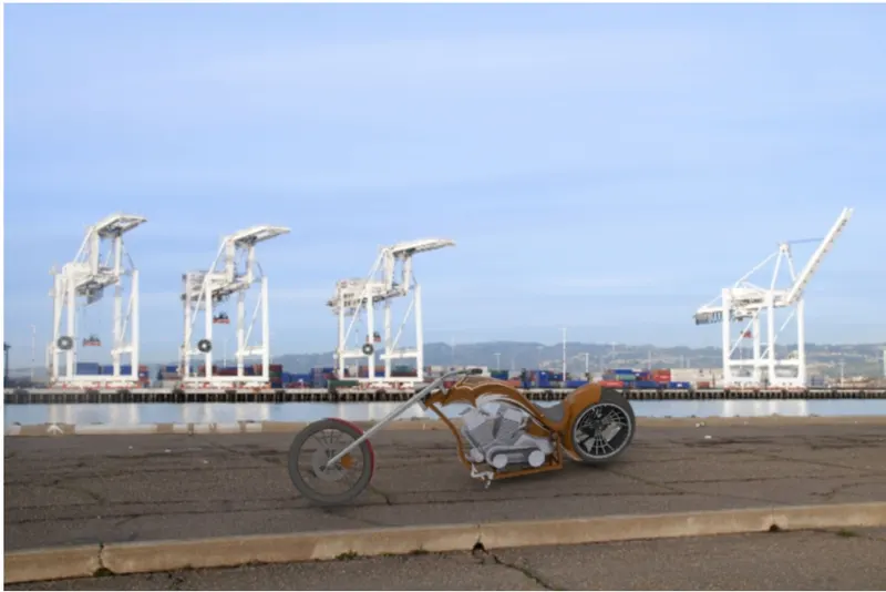
RENDERING IMAGE 1
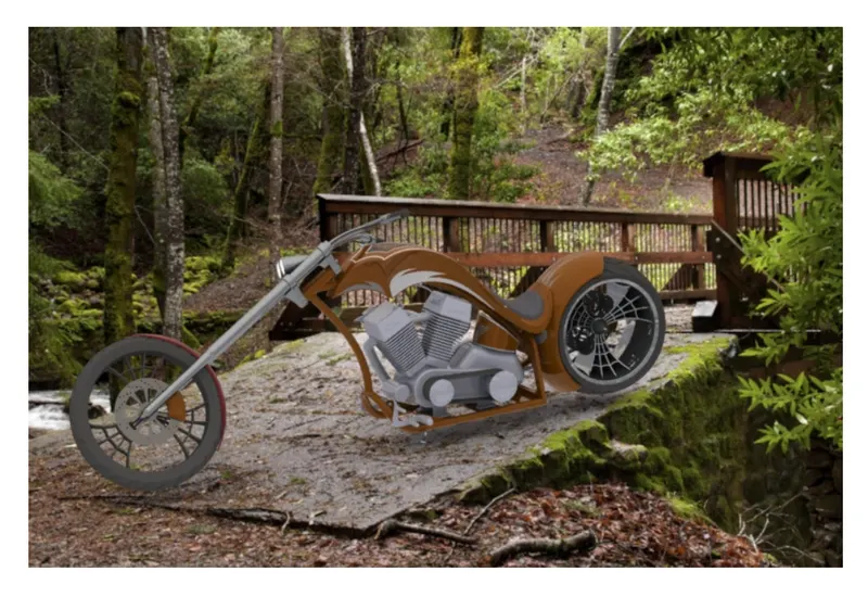
RENDERING IMAGE 2
RENDERING IMAGE 3
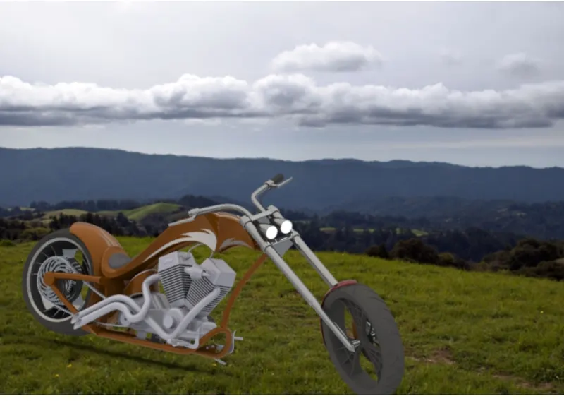
RENDERING IMAGE 4
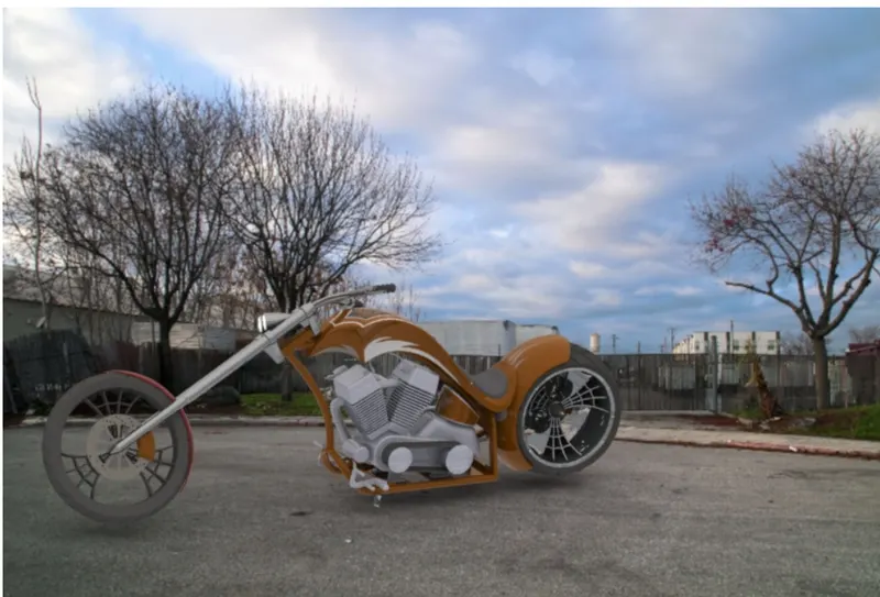
CONCLUSION:
GOOD KNOWLEDGE ABOUT SKETCHING AND SOLID MODELING.
UNDERSTANDING OF ASSEMBLY WORK BENCH.
HOW TO USE ONE AND MORE OPTIONS TO FEW FEATURES.
UNDERSTANDING OF RENDERING AND MORE IMAGES OF CAMERA VIEW SET UP.