Photo Realistic Rendering
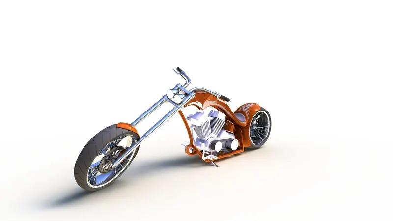
Modelling and Rendering of American Chopper using SolidWorks
I. OBJECTIVES:
The main objectives of this project are-
- To create all the parts of the American Chopper
- To assemble the created parts of the American Chopper
- To apply all the decals, appearances, lights and cameras for the final renders
- To generate photorealistic renders of the final assembled model in PhotoView 360 and SolidWorks Visualize
II. INTRODUCTION:
SolidWorks is a modelling computer-aided designing and engineering software developed by Dassault Systèmes. It has the ability to produce 3D models as well as 2D sketches of the modelled parts. The Add-ins in the software also allows the user to perform many other functions as well like SolidWorks Motion, Simulation and PhotoView 360 for performing more specific tasks in SolidWorks. For example, PhotoView 360 help in creating photo realistic render of the 3D models in SolidWorks.
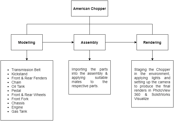
III. PROCESS FLOW CHART:
IV. MODELLING:
Parts are as follows:
1. Transmission Belt:
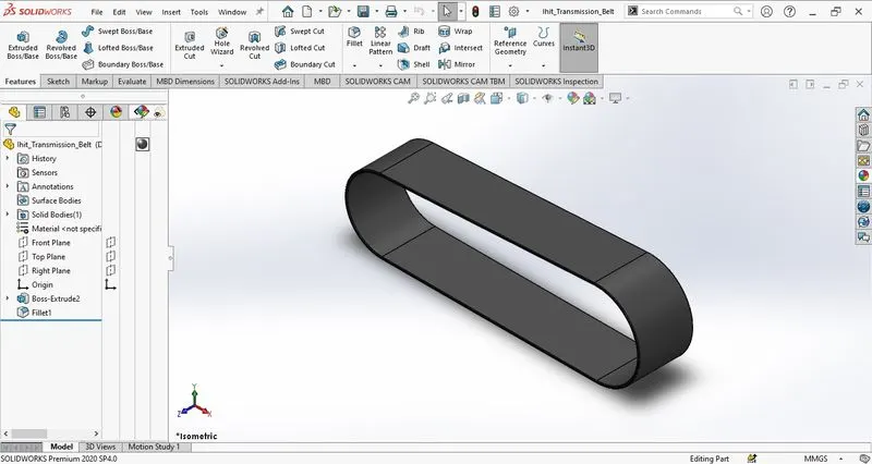
The transmission belt is used to couple the transmission to the engine and aid in transferring power from the engine to the transmission of the motorcycle.
2. Kickstand:
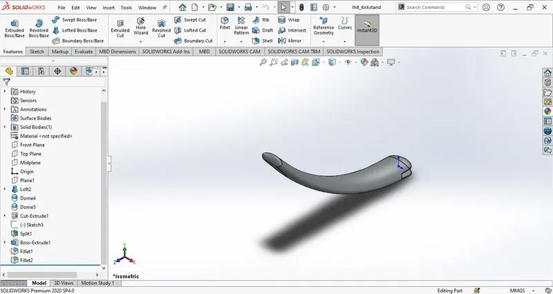
The kickstand is used as a support device on a bicycle or a motorcycle in aid to keep it upright or standing without leaning on another object for the same purpose.
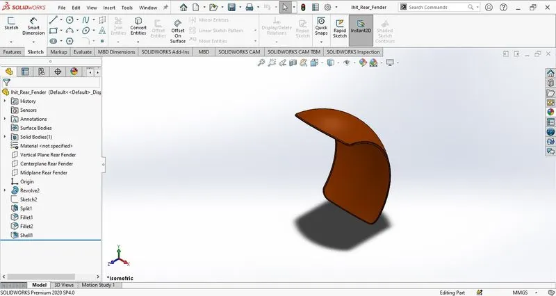
3. Fenders:
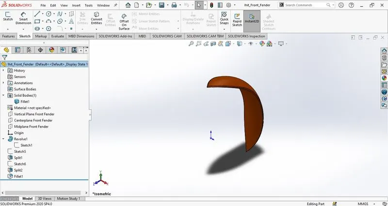
A fender or a wheel cover or a mudguard is a device used to cover the wheel of a vehicle to prevent dirt and water splashes onto the rider from the back as well as the front.
4. Chain:
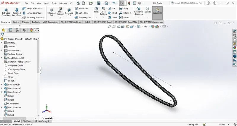
The chain in a motorcycle helps in transferring the power from the transmission to the rear wheel of the motorcycle inturn aiding in the motion of the motorcycle. It is a very crucial component of the drive-train of a motorcycle.
5. Oil Tank:
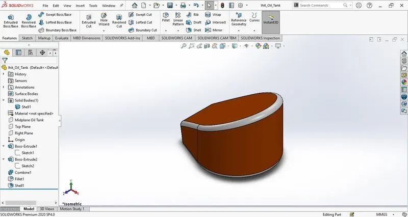
The purpose of an oil tank is to store oil for the chopper engine. These are mainly used in engines with dry sump system, where an oil pan is not feasible either due to design constraints or other factors.
6. Pedal:
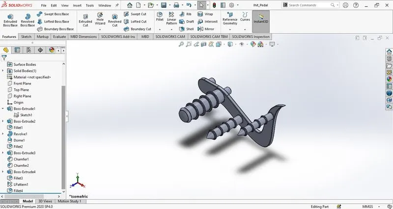
Pedal is used to provide support to the riders feet on both sides of the chopper to give some comfort to the rider while riding the chopper usually it is secured to the chassis.
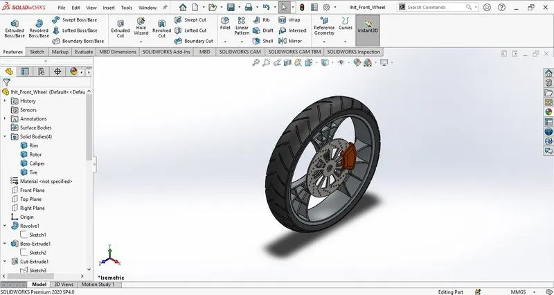
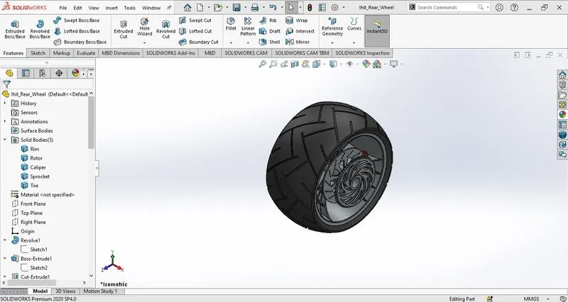
7. Wheels:
They are circular bodies used for the conversion of rotational motion to linear motion. The rubber tires over the rims provide a smoother ride to the rider by absorbing minor shocks.
8. Front Fork:
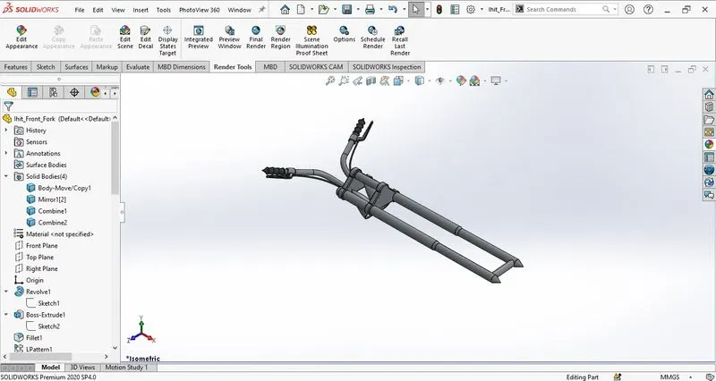
Font fork in a motorcycle is used to hold the front wheel and also help in the steering and handelling of the motorcycle. It has the functionallity buttons on the handles such as horn, headlight, brakes, etc.
9. Chassis:
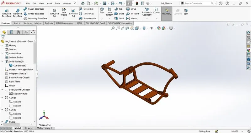
A chassis is a load-bearing framework of a vehicle. It provides structural support to the vehicle in its construction & function as the chassis is what holds all the parts together, i.e., all the parts are attached to the chassis.
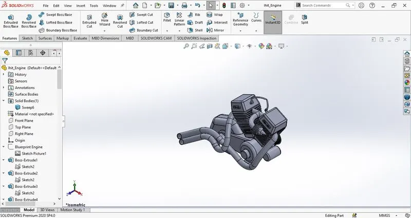
10. Engine:
Engine also known as power pack of the chopper as it provides the locomotion necessary for the movement of the chopper. It is also used to power the auxillary systems in the chopper.
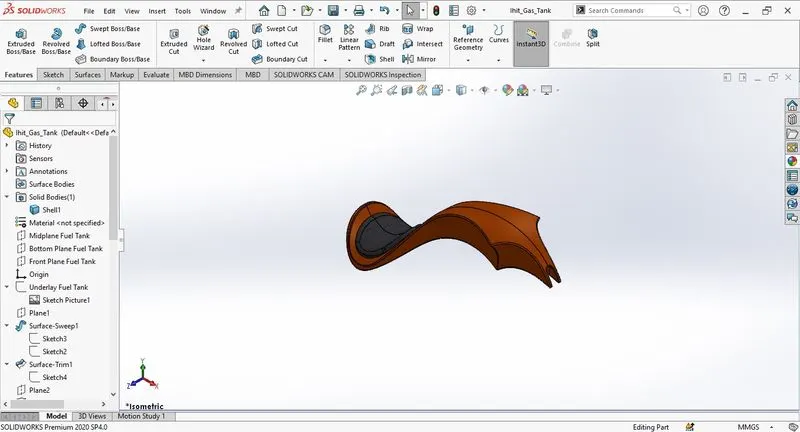
11. Gas Tank:
Gas tank also known as the fuel tank is used to hold the fuel necessary for the chopper engine to utilize in order to produce the power required to propel the chopper forward.
Features used to model the American Chopper:
- Sketch:
It is a 2D representation of a profile of a feature or a 3D model. In SolidWorks, there are various methods to create a sketch such as, line, arc, rectangle, circle, ellipse, etc. These are called as sketch entities.
- Extrude Boss/Base:
This feature helps in converting a closed 2D sketch into a solid 3D profile of a defined thickness. It provides a lot of other options also like blind, bidirectional extrude, offsetting the extrude, up to next, from surface, etc.
- Fillet:
It helps to create a circular profile of a specified radius on the edges of a 3D model by selecting those edges. Fillets can also be applied to multiple edges by selecting all of them at once. We can also create full face fillets and many others.
- Lofted Boss/Base:
This feature helps in creating a 3D model with the help of two or more profiles or sketches. A guided curve can also be used for the loft as it provides more definition to the model. It is a very versatile feature offered in SolidWorks.
- Dome:
This feature helps in adding a dome to a flat face of a model. It gives us the option to select an elliptical dome or a continuous dome and to specify the direction of the dome.
- Revolve Boss/Base:
This feature is used to revolve one or more 2D sketch profile around a given axis of revolution or a centreline. It can be a full 360° revolution or half or a quarter or any specific degree. It offers many other features as well like blind, up to vertex, offset from surface, midplane.
- Split:
It is used to split or divide a part into multiple bodies along a selected face. The divided bodies can either be consumed or can remain as is according to the needs of the model. It is a very useful feature in SolidWorks.
- Blocks:
Blocks can be created by grouping single or multiple sketch entities. The entities in a block are treated as a single object. They help in reducing the time required for modelling multiple similar objects by importing geometry and constraining only one entity instead of constraining multiple of entities.
- Pattern:
- Linear Pattern:
It helps to create a linear pattern of a sketch or a feature. With the help of the pattern the modelling time is reduced as one or more entities of a feature or a body is required to create a pattern. The number of instances required can be defined. For direction, a reference geometry can be specified and the required direction can be specified.
- Circular Pattern:
This feature creates a circular pattern it is similar to a linear pattern. For the pattern axis, a reference geometry can be specified like a revolve axis, cylindrical face or surface or a circular edge.
- Curve Driven Pattern:
It helps to create a pattern that is dependent on a specified curve. This helps us to create a pattern with multiple radius of curvature. For the direction of pattern, the curve along which the pattern is required has to be selected.
- Mirror:
It is used to mirror features or bodies along a plane or face. It is used to reduce the modelling time as only one side of a symmetric part can be modelled and mirrored later when all the features are added to one half.
- Combine:
It is used to merge two or more bodies as one body. It is used when bodies are modelled separately but are a part of one parent model, all the parts are combined as one so that applying properties and appearance becomes easy.
- Shell:
This feature is used to hollow out a part and create thin-walled features. Features with a uniform thickness or multiple thickness can be created.
- Chamfer:
This feature allows to create a bevel profile at the edge of the model. It offers multiple options like distance-distance, angle distance and vertex.
- Extrude Cut:
This feature is similar to the extrude boss/base feature the only difference it has is this feature is used to remove material from the part unlike the other feature which is used to add material to the part.
- Revolve Cut:
This feature has a resemblance with the revolve boss/base feature. Unlike the revolve boss/base feature which is used to add material around a revolution axis or centreline this feature is used to remove material by revolving one or more profiles around a centreline or revolution axis.
- Swept Boss/Base:
It is used to create a boss or base by traversing a profile along a specified path or a guide curve. This feature requires a sketch profile or multiple sketch profile and a guide curve. It offers multiple options like orientation/twist type keep normal constant, follow path.
- Swept Cut:
Similar to the swept boss/base feature the swept cut also uses a profile sketch and a guided curve to move along but instead of adding material like the swept boss/base it removes material along the path.
- Projected Curve:
This helps to create a 3D curve with the help of sketches on different intersection planes. To produce a projected curve the surfaces are extruded from the sketches selected and at the intersection of these surfaces the curve obtained is the 3D projected curve.
- Swept Surfaces:
This feature is similar to the swept boss/base feature as this feature also requires a profile sketch and a guide curve. It sweeps the profile along with the guide curve and creates a surface.
- Lofted Surfaces:
It creates a lofted surface with the help of multiple profiles similar to the lofted boss/base feature. A guide curve may or may not be necessary, it can be added if needed.
- Extrude Surfaces:
It is very similar to the extrude boss/base feature as it is also used to extrude a sketched profile but in the form of a surface instead of a solid body. It offers the same features like the extrude boss/base feature.
- Knit Surfaces:
Like the combine feature in solid modelling, the knit surfaces feature is used to combine two or more surfaces into one. The surfaces to be combined have to be selected and then knitted together.
V. ASSEMBLY:
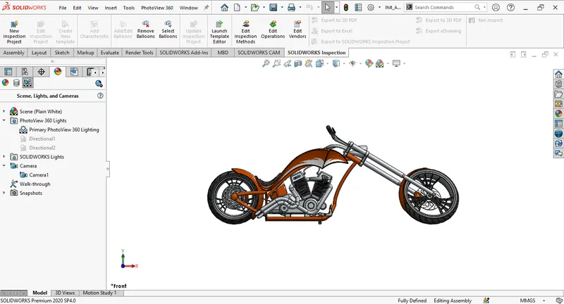
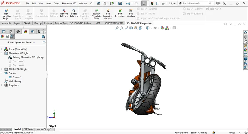
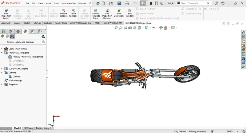
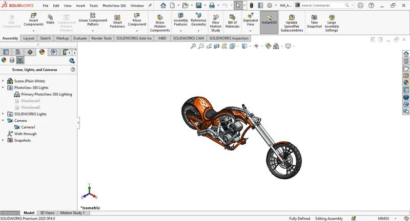
In assembly, all the modelled parts are imported and required mates are applied to the parts to assemble them in the desired position. Assembly helps us to see all the parts at their allocated locations on the final model and allows us to make a few last-minute tweaks according to the needs and to fix the errors made during the modelling process.
Snapshots of the Assembly:
Front View
Side View
Top View
Isometric View
Camera Setup
VI. PHOTO-REALISTIC RENDERRING:
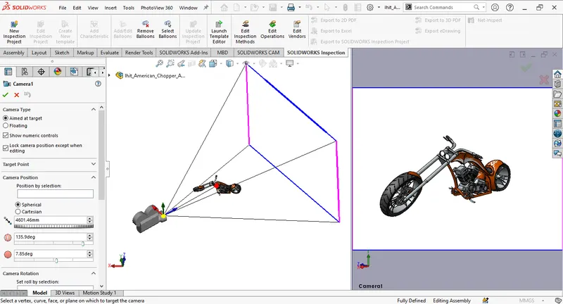
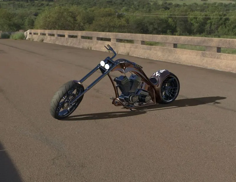
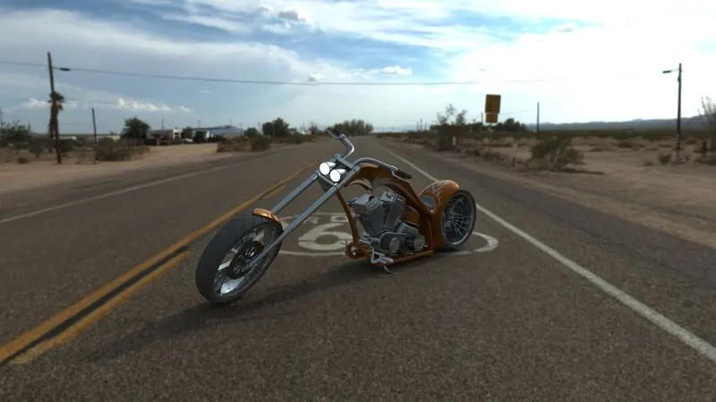
In photo-realistic rendering the prepared model is set up in an environment along with the cameras at suitable angles and environment lighting. This helps in blending the model into a realistic environment and to give an idea about how the model will look in the environment for which it was designed. For this purpose, we use PhotoView 360 and SolidWorks Visualize.
Renders of the American Chopper using SolidWorks Visualize:
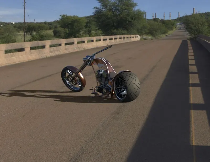
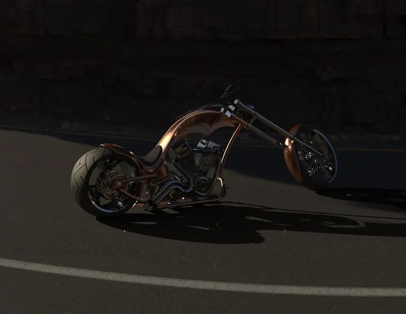
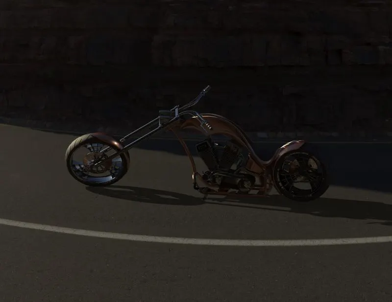
Renders of the American Chopper using PhotoView 360:
VII. CONCLUSION:
In conclusion to modelling the American Chopper we learned-
- To convert 2D sketch profiles into 3D models.
- To use the features available to ease the modelling process.
- To assemble the modelled parts with the help of available mates.
- To render the images of the model by setting it up in an environment and fixing the lights and camera.