Photo Realistic Rendering
BY KAIF AHMED
MODELLING OF AMERICAN CHOPPER
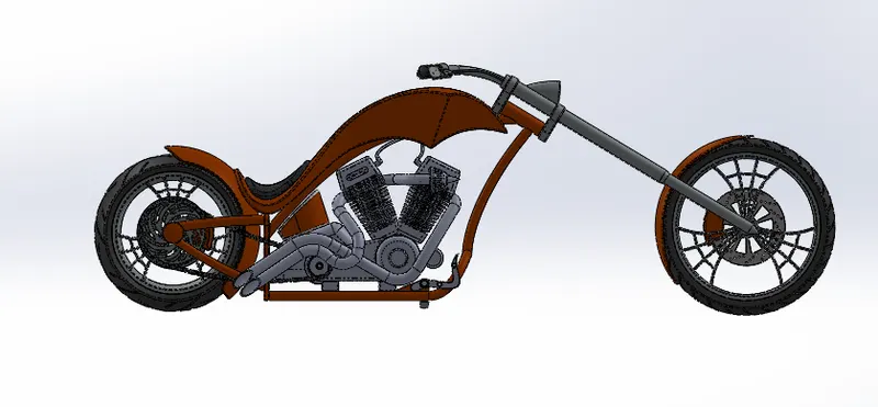
INTRODUCTION:
In this project we are going to learn the entire modeling of an American chopper on solid works and solid works visualize.
The different components of the American Chopper we will be dealing with are:
- Chassis
- Engine with exhaust system
- Front wheel and Rear wheel with rims sprockets,calipers and rotors.
- Front fork along with handlebars and grips
- Front and Rear Fenders
- Oil Tank
- Chain and transmission belt
- Kick stand and foot pedals
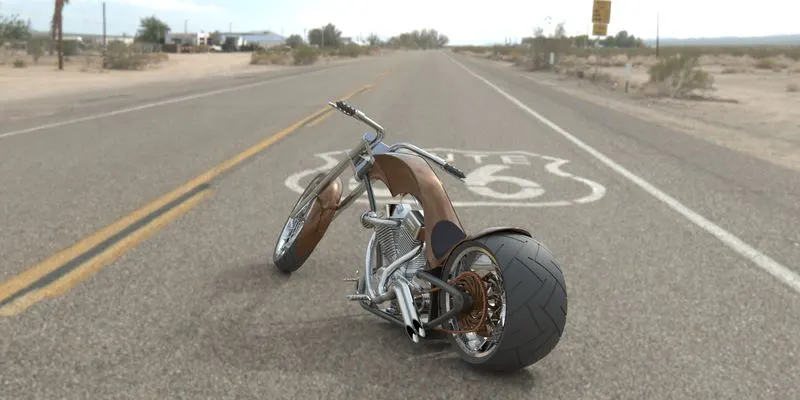
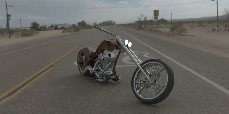
After designing the components part by part , we have worked upon the assembly and the photo rendering of the chopper which gives it a complete and realistic view.
DESIGN APPROACH:
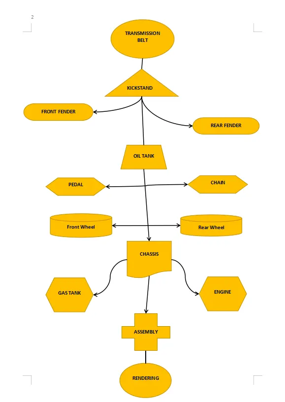
Starting with the transmission belt and ending till the rendering section has been described step by step by means of a flow chart.
Now we will discuss what are the features and properties used in the entire model to design different parts:
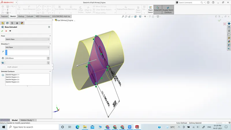
- Extrude Boss: The Extruded Boss is one of the most basic of all SOLIDWORKS features and extrudes a sketch along a straight-line path to add material. A proper sketch is required before applying the Boss extrude feature hence it is important that we select the closed sketch properly , after that when we apply the Boss extrude from the features tab a feature box pops out which requires several parameters on how much distance do we want to extrude the surface and whether is on both sides , or through all or up to a surface or maybe apply an offset distance as well , various properties are available including the draft feature as well .
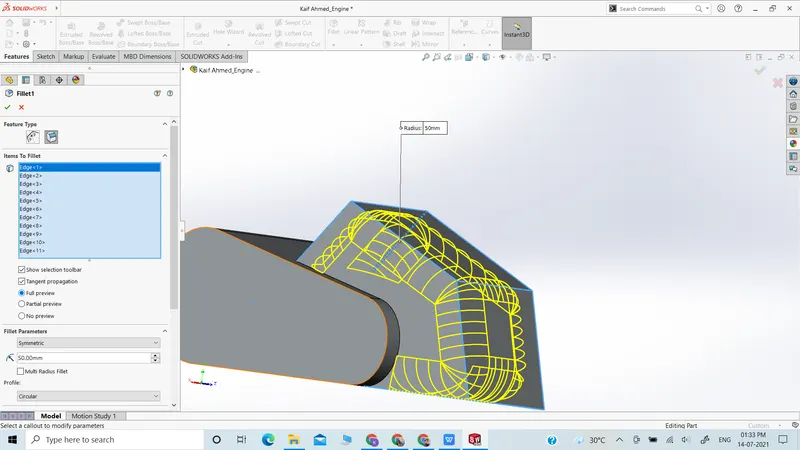
- Fillet: Fillets are classified as applied features, which means they do not require a sketch as such , a solid body is enough for applying rounded edges to it . And this feature can be applied separately with different radius value . Furthermore several other features are available as well included with this which are rounded edge fillet , face fillet etc.
- Revolved Boss Feature: Adds material by revolving a sketch around an axis. For using this feature it is important that we develop a closed sketch and an axis around which it can revolve . It is important that the distance between the axis and the solid sketch to be revolved has a feasible enough. There are additional features of revolving up to a certain extent and not full 360 degrees in nature . Along with this we can flip the revolve feature as well .
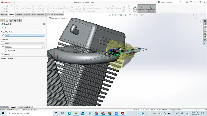
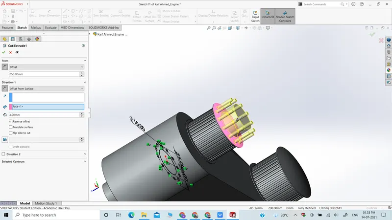
- Extrude Cut: Similar to the extrude boss feature this feature needs a sketch which will be used to cut off a certain segment in a straight direction . Similar to the features of extrude Boss we can cut through all or up to a certain distance in the solid body.
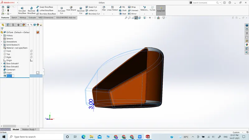
- Shell: SolidWorks shell tool is mainly used for shelling process, in which a closed solid body is converted into a hollow closed or open body depending on the sketch and a small thickness is kept using the shell feature .
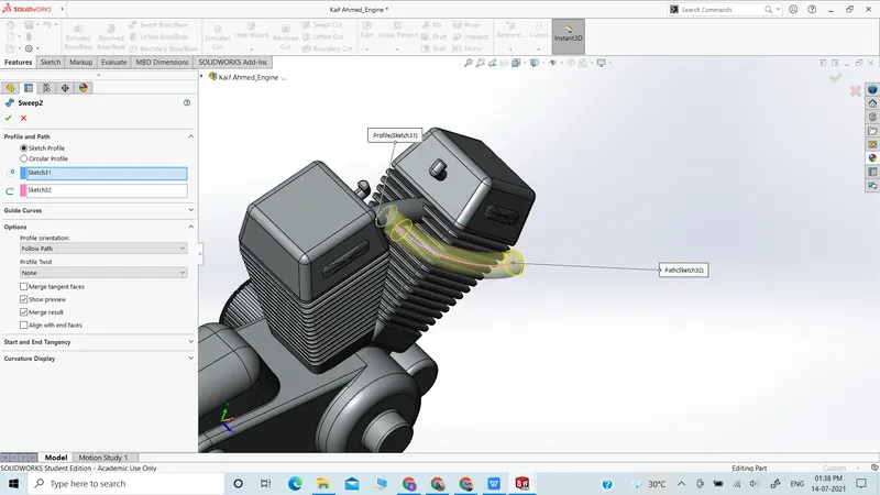
- Sweep Boss / Sweep Cut: Sweep creates a base, boss, cut, or surface by Selecting a closed sketch and moving it along a curved path to generate a profile . It is necessary that the base is closed surface and the profile may be closed or open in nature . In case of sweep cut its is similar to extrude cut but in this case it is important that the curved path along which the profile cut will be generated is well defined.
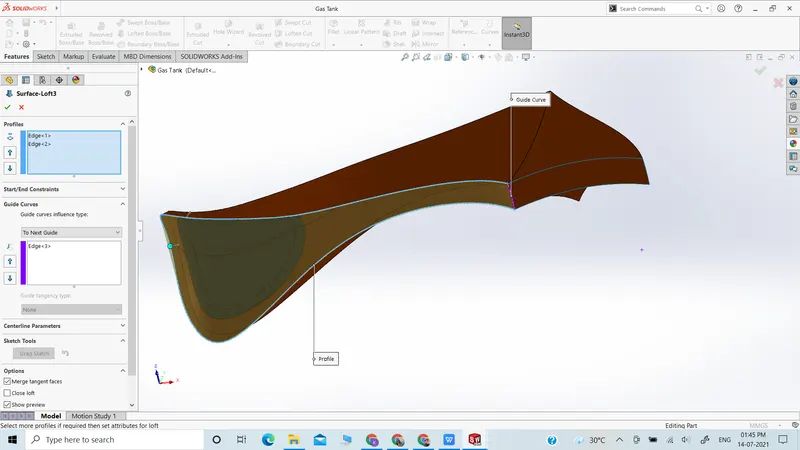
- Loft Boss/ Loft Cut: The loft feature is an important tool for (surface) modelling in SolidWorks. Unlike extrude boss the loft boss can extrude any surface in a complex profile rather than in a straight direction . It uses a combination of curved profiles and guided curves to form cool and dynamic surfaces which cannot be developed by extrude boss.
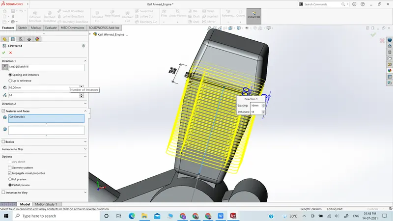
- Linear Pattern: Wecan use linear patterns to create multiple instances of one or more features that we can space uniformly along one or two linear paths. Pattern formed by linear pattern feature can have different orientation and direction but it will always be in a straight direction and not in curved nature .
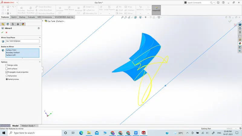
- Mirror: Creates a copy of the features we want to mirror about a plane or a face . In case of mirror features , the specific features are mirrored about the plane and the surfaces of a single body or multi body .In case of Bodies to be mirrored we do not require to select the features separately , it will automatically get featured on the other side without any discrepancies . For allowing specific features to be mirrored we have to deselect the ones we do not require and allow the ones we require .
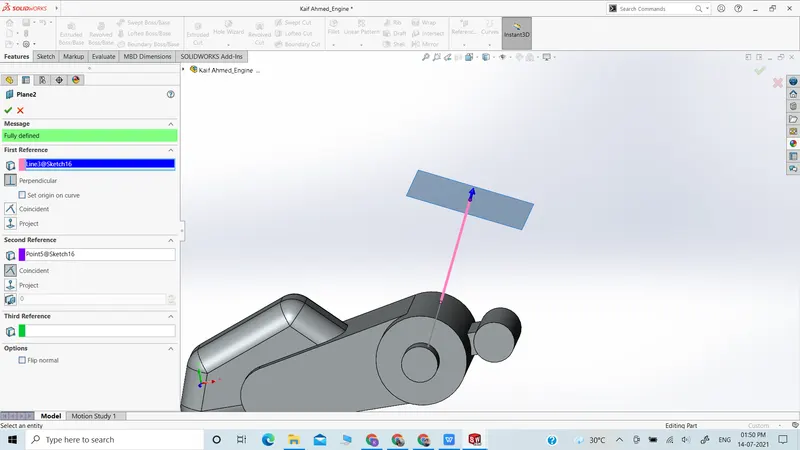
- Reference Geometry: Reference geometry defines the shape or form of a surface or a solid. Reference geometry includes several types of geometry which includes planes , axes , coordinate system and points. The major advantage is that we can create planes anywhere necessary which further helps to make sketches at places which are complicated to reach and hence make extrude bosses or sweeps. For example:-
- Planes are used in lofts and sweeps.
- An axis is used in a circular pattern.
- Projected Curve: This feature helps in developing complex curves which cannot be created on sketch as a 2D variant . Projected curves produces the intersection of two curve surfaces in a 3D space and we can create extrude sweep or boss out of it to develop curved surfaces and protrusion out of it. Note: the Projected Curve tool does not support projections of intersecting curves.
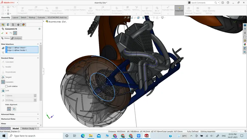
Mate : Mates create geometric relationships between assembly components. As we add mates,we allow definable movements for the assembly parts , the parts can be rotated or moved along certain axis . Mates is an extremely important feature for assembly of parts into a single body. Furthermore we have relation properties like co-planar , concentric,tangent,coaxial etc .
- A coincident mate forces two planar faces to become co- The faces can move along one another but cannot be pulled apart.
- A concentric mate forces two cylindrical faces to become concentric. The faces can move along the common axis but cannot be moved away from this axis.
Mates are solved together as a system. The order in which you add mates does not matter; all mates are solved at the same time. You can suppress mates just as you can suppress features.
Now as we have completed discussion of how the features work under solid works let us see the application of the features in the chopper that we have built. We are going to discuss part by part as shown in the flowchart.
Transmission Belt: The solid body in transmission belt is a single extruded surface whose outer edge has been filleted and the appearance used is a matte rubber. In this sketch we have used the property of offset figure which helps a lot to develop a part.

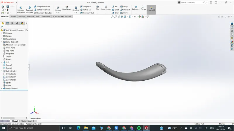
Kickstand: While designing the kickstand we used the sketch drawing based on an additional plane, the sketch was used to create a lofted part and the dome features were applied on both the ends, After that we used the bottom plane to make a sketch and hence use the split tool to develop a flat surface on one of the ends of the kickstand n so that the chopper will be placed in an environment properly . At the end we added a chrome finish to the whole solid part and hence created a kickstand.
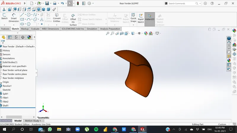
Front Fender: Here we have revolved the sketch using the axis again is a single solid body , with a revolution degree less than 360 degrees because we do not want a full circle . Where both the sides have been designed with the help of sketches and the split tool. The outer edges of the fender are filleted.
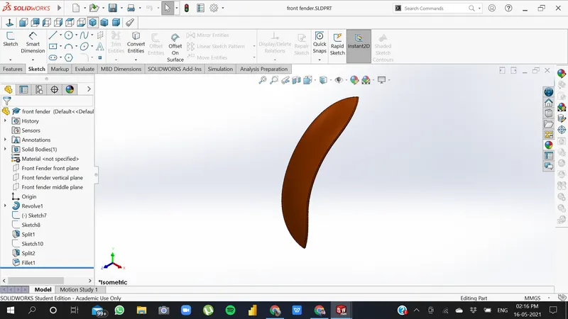
Rear Fender: The same method has been applied in the rear fender as it was in the front fender the only difference between the two are the sizes of both the fenders which vary accordingly with the size of the tire which means that dimensions of the sketch which we used will be different in both the cases and it is important to specify the fact that the fenders are not alike. Both the parts are metal and painted sienna which gives a bright orange texture.
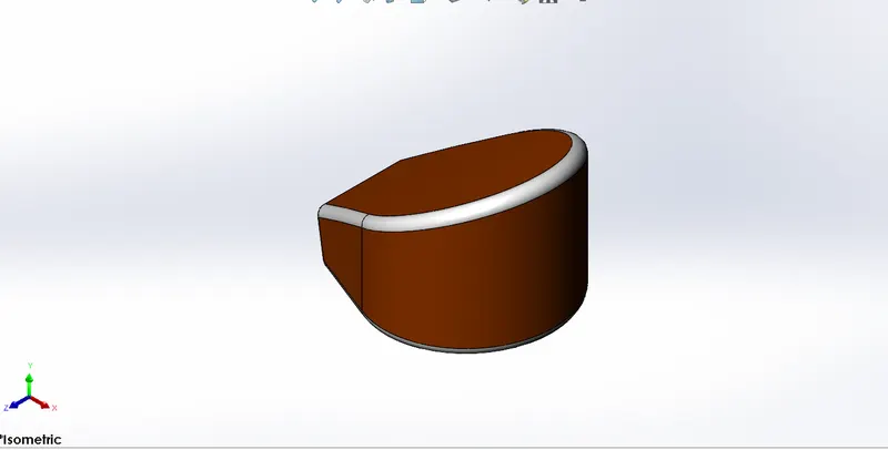
Oil Tank: The base of the oil tank is sketched on the Top Plane and extruded boss above now to attain the structure of the oil tank one more sketch is made on the mid plane extruded and combined together to obtain the final solid shape and at last a shell function is used to make the part hollow and the edges are made round by applying fillet. Again the metal body is painted with the same sienna color and the filleted edges are given a white paint.
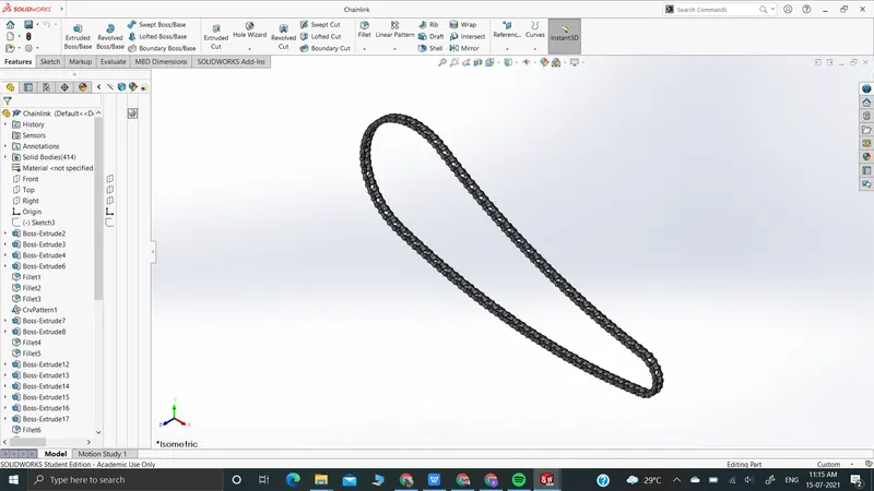
Chain Link: This is one of the most complicated part in the whole model . In this case we have too create two linkages and save it accordingly . After that the curved sketch of the chain is made where we can connect the two links at one point and then accordingly apply curved pattern along a the sketch part by part to complete the line . At the end we will apply mirror feature to the link created and accordingly the chain will be developed . Finally a chrome finish is applied.
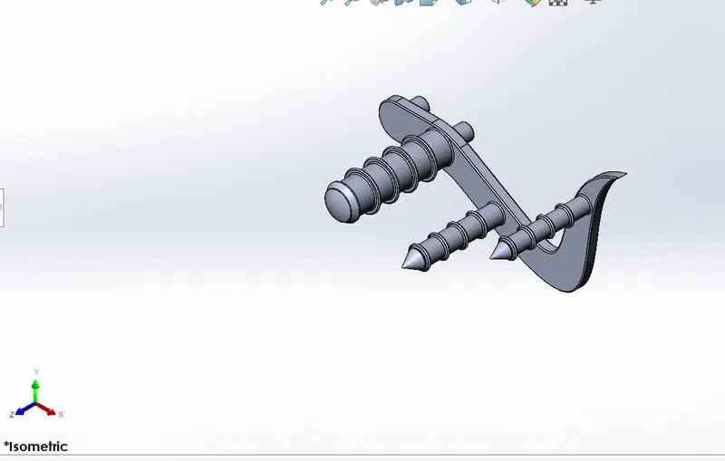
Pedal: The design starts firstly drawing a sketch using split diagrams and hence developing the sketch and then gradually we will look into extruding it upto a certain thickness . After this we will create dimensioned circles on one of the face of the solid body and then extrude it accordingly we will set domes on one of the extruded cylinders and then use chamfered option to apply conical shapes to the end of the other extruded cylinders. After that we will apply circular rings around the cylinders and apply a linear pattern to it . At last we will apply fillets to all the necessary edges and hence complete the part . We will also provide a chrome finish to it .
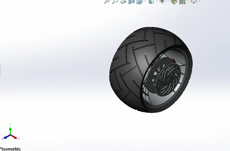
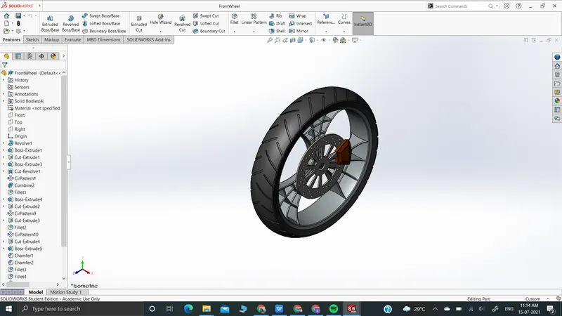
Front and Rear Wheel: The designing of both the wheels are similar the differences is in the size of the wheels. The only difference lies within the dimensions of both the wheels . To start off we are going to firstly create a revolve sketch along a common axis and set the necessary dimensions. After that we will start creating the rim of the wheels which of spider web design in nature it is important that the rim spades or the wheel spades are tangent to the inner surface of the wheels . After this we will use offset features , split features and extrude cut to design the web pattern around the rim . After creating one spoke we will apply circular pattern to it . Once it is done we will use convert entities to develop a smooth and curved cut around the rims so that the solid body is accurate in nature . Following this we have to create the break rotor which is a simple circular solid body with circular patterns of holes and a cut section . After this we have to develop the caliper which is attached to the rotor ,this calliper will be trapezoidal in nature and is attached to the rotor . Apply necessary fillet to the caliper . One of the major difference between the front anc back wheel is the inclusion of sprocket for the chain in case of the rear wheel , here will also take help of 2D split feature and circular pattern and extrude cut. This is attached above the rotor and the caliper . Finally we will apply the outer surface on the rim for the rubber tire with different dimensions for rear and front wheel respectively . Finally apply the necessary finish material which are chrome finish to rims , sprocket and rotor . Siena paint to the caliper and gloss rubber to the outer surface of tire .
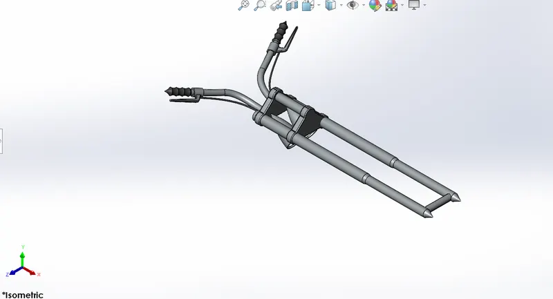
Front Forks: - This part consists of front fork, handle bar, head lights, break and clutch levers, wires and handle grips. The idea to design the fork is to make one side of the fork or half the fork and then mirror it along the face and make cables and handle grips. The design is started with revolving a cylindrical fork along right plane then on the top of it the face is sketched and extruded which is mirrored and linearly patterned then with two cylindrical extrudes to join the upper deck and the mirror side of the fork. Another extruded part is curved along the top of the handle facing down which is the headlight. To make it hollow a part is extrude cut internal from the face of the headlight. The edges of the part is filleted to give it a headlight curved look. After all we focus on the handle which is sweeped using two curve used to form a projected curve and similarly on the front face of the sweeped area handle grips are made using the revolve feature and on the inner face of handle bar we draw the geometry required for the levers and extrude them the sharp edges are filleted and then comes another projected curve made to sweep the wires for the brake and clutch now we create a plane from which the other side of the fork is mirrored and all the parts are combined together to form the desired 3D shape.
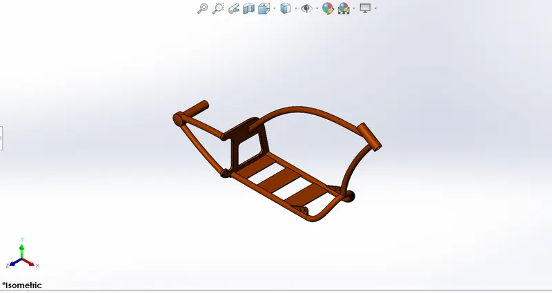
Chassis: The plan of chassis starts with attracting two extended bend to achieve the lower bended way of the square which is sweeped along the way which is then reflected to accomplish the lower math, a sketch is made and expelled from the open finish of the base and a square is made a section from the square is expelled out calculatedly to accomplish the ideal shape and the foundation of the square is chamfered and the sharp edges are fileted both on the outside and the inside two additional breadths are made and two more expelled math is produced using the square to make the connection needed to go along with it with the sprocket, to make the upper pole of the skeleton one more compass is made from the front essence of the square and the split device is utilized to remove the extreme materials, to get the suspension together with the front fork a rotate part is made at the front and other the joints between the two sweeped bars is expelled, presently to make the connections with the pedals and the kick stand two calculations are made expelled and the undesired part is expelled out. Toward the end every one of the sharp edges go through wanted filet and a plane is added with the end goal of the further gathering purposes.
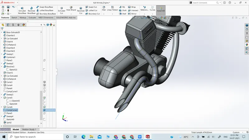
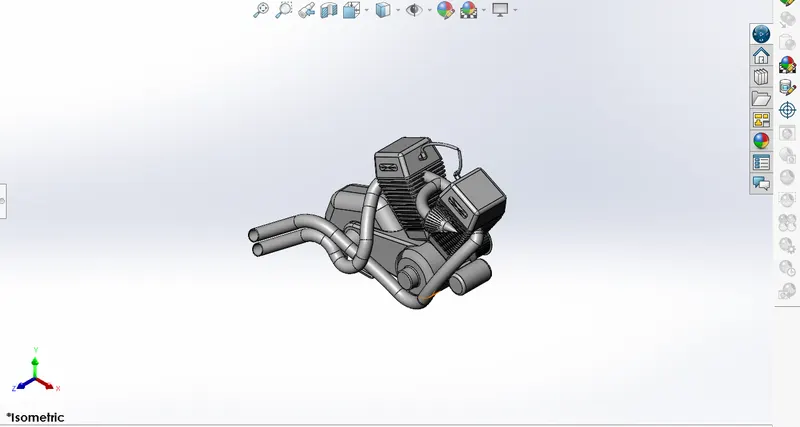
Engine, Motors and the Exhaust System: A sketch is made on the front plane and expelled which is the plan of the foundation of engine and a few supervisors are made alongside a similar sketch to accomplish a legitimate shape next the upper bended part is expelled and every one of the edges are fileted to achieve the shape
Presently on the back side of the engine two rotated highlights are made to make the game plan for the transmission belt and the spokes are made utilizing the expel and straight example around the roundabout district and same interaction is utilized on the opposite side of the expel as well. The front of the round and hollow expel is then removed with the ideal shape
The rear of the engine the motor case and the highest point of the case is outlined and expelled in a steady progression and converged with the whole body a section from the motor body is removed to make the blade which is directly designed all through the surface as displayed in the fig. what's more, the fillets and chamfer are utilized . Presently at the best a sketch is made and the sparkle plug is made with that the state of the motor is currently reflected for the twin chamber. Then, at that point the front stuff is made for the steel utilizing expel and cutting the edges of the 3D roundabout expel as the plan requests, and at the foundation of the motor center the four stand are made for the gathering purposes a connection is then sweeped between both the motors. Presently comes the planning of the fumes pipe from the motor to do that two projected bend is made both the bends are then consolidated to frame a composite bend which is sweeped right from the beginning essence of the motor to the back as indicated by the measurements a similar cycle is done for the subsequent line and finally the wires are connected to the sparkle plug with two unique ranges. The complete appearance given to the motor is chrome plate metal.
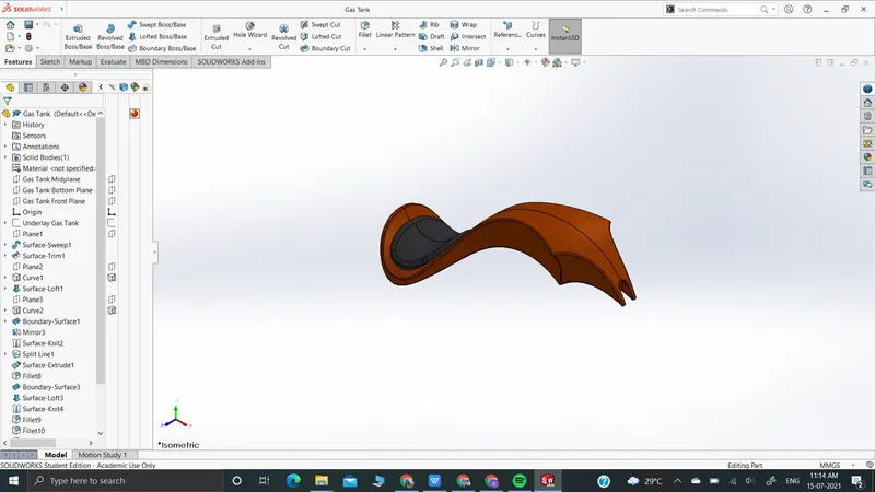
Gas Tank: To get going we should realize every one of the highlights utilized in this go under the surface segment of demonstrating, we start by making an extra reference plane and draw two portrays on it which is surface sweeped to accomplish the essential format of the fuel tank, presently the edge is surface managed to achieve the plan of the tank one more plane is added and a surface space is made as the front substance of the tank now with the assistance of limit clear component the front face and the side face are combined with the back of the fuel tank currently reflecting the whole part and weaving them together we get the whole fuel tank structure, presently at the backside we make a seat by expelling the surface and fileting the edges of the seat to give an adjusted look now with surface space and sewing apparatuses we give a covering to the lower part of the fuel tank, a sketch is drawn at the essence of the fuel tank to cut the u segment for the gathering of the tank with the frame and every one of the sharp closures are then fileted a shell is made toward the finish to make it empty. Again the base sienna tone has been applied to the part and a dim cotton material is utilized for the seat the decals are utilized which will be talked about under delivering the part.
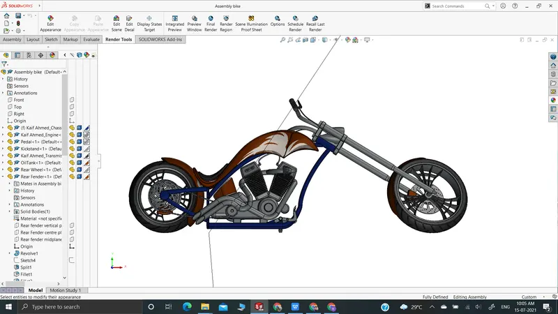
Assembly: Subsequent to making every one of the parts the main piece of amassing the whole chopper to a solitary document starts. To begin we start by getting the undercarriage first and utilizing its plane and math as a base for the whole strong gathering, the second part we get is the motor the base remain of the motor is tangled correspondent with the foundation of the frame then the planes of the motors are mated so it is a fixed body and doesn't move finally a distance mate is applied so the part is completely characterized, after that we acquire the pedal the pedal has the pins which are mated with the openings in the body and an incidental mate is shaped to make the part fixed now as we need pedal on both the sides a similar pedal is then reflected on the opposite side of the body with characterizing the properties of the contrary side, presently we get the kick remain here he first mate made is a concentric with the opening made in the skeleton and the expelled part in the stand the to characterize the rakish pivot of the kick stand a precise mate is furnished with the body so that there is no aggravation with model, presently we bring the transmission belt which is mated on the motor drivers to completely characterize this with the mates we give a point to make the joint correspondent with the drivers, next we get the oil tank which is straightforwardly positioned and tangled over the motor, presently comes in the back tire which is concentrically tangled with the body and the center of the wheel the planes are mated in like manner and an equal mate is applied to completely characterize the sketch, the back bumper is currently applied over the back tire, presently the steel is welcomed on to begin a width mate between the steel parts and the sprockets of the back tire and the motor, presently the fuel tank is fixed with a distance mate and an equal mate concerning the body, the front fork is mated coincidently with the upper piece of the suspension and a width mate is applied to hold the upward movement of the fork now for the turning point of the forward portion of the chopper a point mate with specific impediments is applied with the fork and the body, at long last the front wheel is appended with the front fork as it was connected in the event of the back tire and the bumper is put over the front wheel as displayed in the chart.
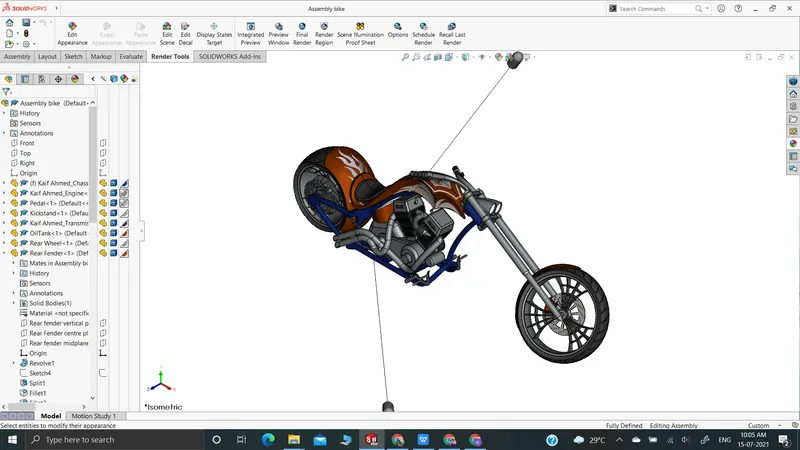
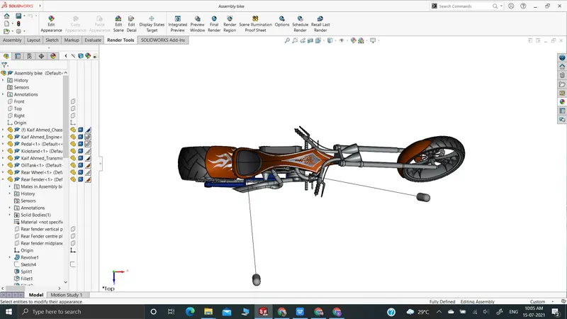
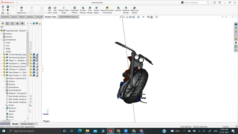
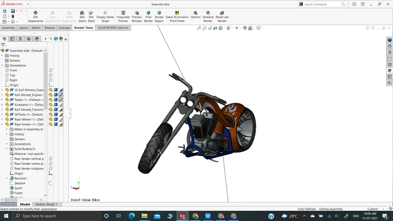
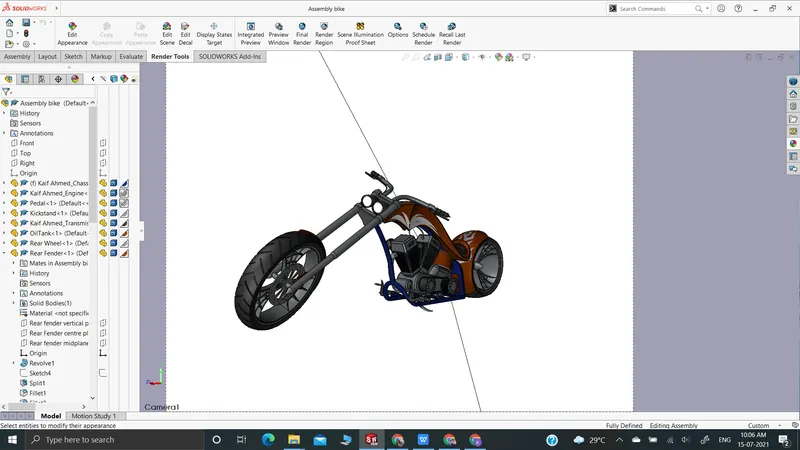
Rendering: The last advance of the chopper to make it look reasonable as we have as of now talk about the employments of delivering a model here we attempt to make it look however practical as it might have been conceivable we gotten going with checking the appearance added on every one of the parts then we to make it look more beautiful we add a few decals on the back bumper and the substance of the oil tank, presently we attempt to make it more sensible by giving it a camera see setting the ideal lights and the central distance making the point of the view and saving the camera point which gave a sensible view to the chopper. Presently we take our get together document into strong works imagine where we begin making the item increasingly more practical with adding the foundation changing the and changing the brilliance, shadow thickness and gamma levels as indicated by the various necessities of the various foundations changing the shade of the model and checking what suits the best with which foundation until we get the ideal and shocking item prepared.
CONCLUSION
At the end of the full project I have gained enough knowledge to operate SolidWorks software efficiently and hence create a complex solid model like the above American Chopper. The most important aspect of the whole project is the provision of discipline , dedication and the amount of detailed work necessary for the model. At the end the features of Solidworks Visual helped me to provide a realistic view to the chopper and hence make it look professional enough .