Photo Realistic Rendering
Modelling of American Chopper by modelling and assembling different parts in Solidworks
Introduction:
Solidworks is the one of the most used and user-friendly designing/modelling software. The software enables the user to model/create 3D parts by sketching (2D sketch). Using Solidworks, one can not only model a part, but also apply a specific material, a suitable background, decals and many more cool and interesting features. For rendering the modelled part or for giving the modelled part a more realistic view or appearance, Solidworks has an add-in feature namely photoview360.
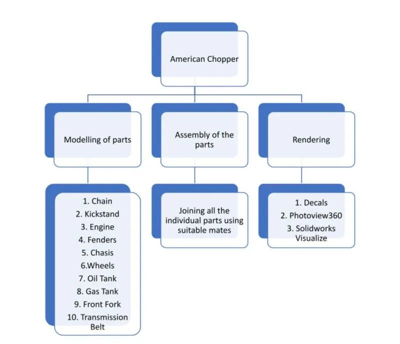
The main aim of the project was to learn about the features available in Solidworks, by creating the parts of the American Chopper and then finally assembling them all together to obtain an American Chopper and then at the end rendering the assembly to get realistic look.
Objective:
The main objectives of the project were:
- To initially create the required parts
- To give the parts a proper appearance
- To assemble the parts together to obtain the final assembly
- To give the final assembly a more realistic view by rendering using photoview360 and Solidworks Visualize and side by side using features such as lights, camera, decals, etc.
Design Methodology/Approach:
Chain:
Chain is a transmission system that transfers power from the engine to the wheel (Rear wheel). Sprockets and chains are used for power transmission from one shaft to another.
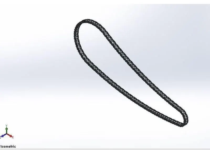
Features used to model Chain:
- Sketch
- Boss Extrude
- Fillet
- Blocks
- Curve driven Pattern
- Appearance
Blocks:
- First create a sketch
- Click on Make Block
- Select the sketch entity
- Click on OK and save
- Repeat the steps 2-4 to create another Block
- Necessary relations can be added with the sketch still in edit mode.
- Finally save the part
Boss Extrude:
Boss Extrude feature allows to add thickness to a 2D sketch in a third dimension.
Fillet:
Fillet is used to create a rounded internal or external face on the part.
Curve driven Pattern:
Curve driven Pattern allows the user to pattern a feature, face or a body along a curve. The curve can be generated from features such as a split line, a projected curve, a composite curve and so on.
Kickstand:
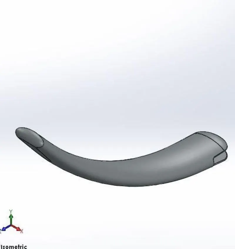
Features used to model the Kickstand:
- Sketch
- Loft
- Boss Extrude
- Dome
- Extrude Cut
- Fillet
- Split
Loft:
It is used to create a complex geometry in a single feature. For example, creating a surface between two different cross-sections. It does so by interpolating surfaces between the cross-sections of the model.
Dome:
Dome is a feature used to give a curved formation or shape just like half of a sphere. The dome feature can be applied to faces whose centroid lies outside the face.
Extrude Cut:
This feature as the name suggests, is used to remove, or cut material from the §D part/model. It cuts based on the sketch profile (in single or both directions).
Split:
The split tool is used to project a specific entity on a surface (curved or planar).
Transmission Belt:
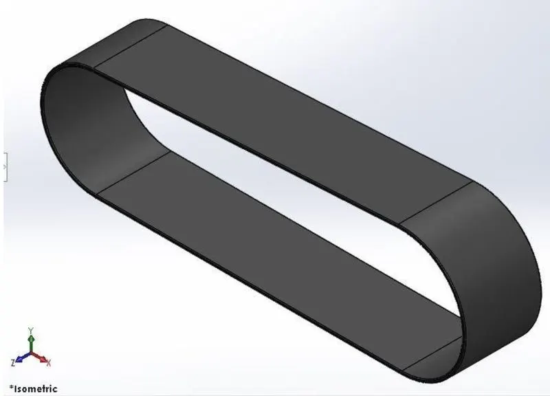
The use of the Transmission belt is to transmit power from the main Engine to the Gear box.
Features used to model Transmission Belt:
- Sketch
- Offset Entities
- Boss Extrude
- Fillet
- Appearance
Offset:
Offset entities takes a copy of the existing geometry and copies it at an offset (inside or outside). Any sketch feature can be offset.
Front Fender:
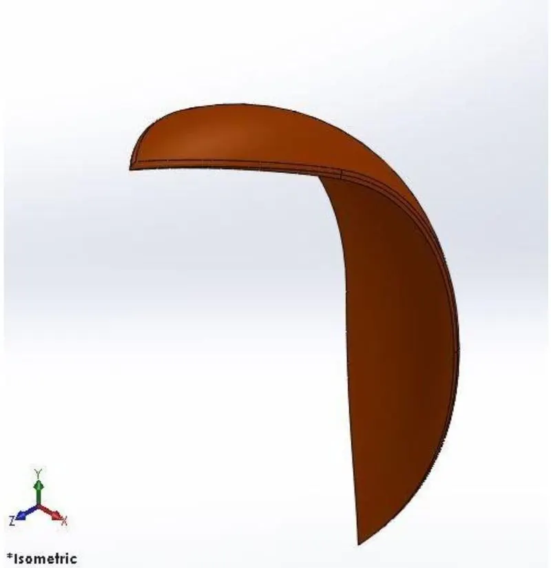
The front fender is a part which is mounted above the front wheel with an offset to protect against debris and other particles.
Features used to create Front Fender:
- Sketch
- Offset Entities
- Trim
- Revolve
- Mirror
- Split
- Appearance
Revolve:
The revolve feature is used to revolve a 2D sketch along an axis or a centerline.
Mirror:
The dynamic mirror function is used here. Using this feature, the line or lines which are to be mirrored about are preselected, then anything drawn in the sketch will be mirrored dynamically.
Rear Fender:
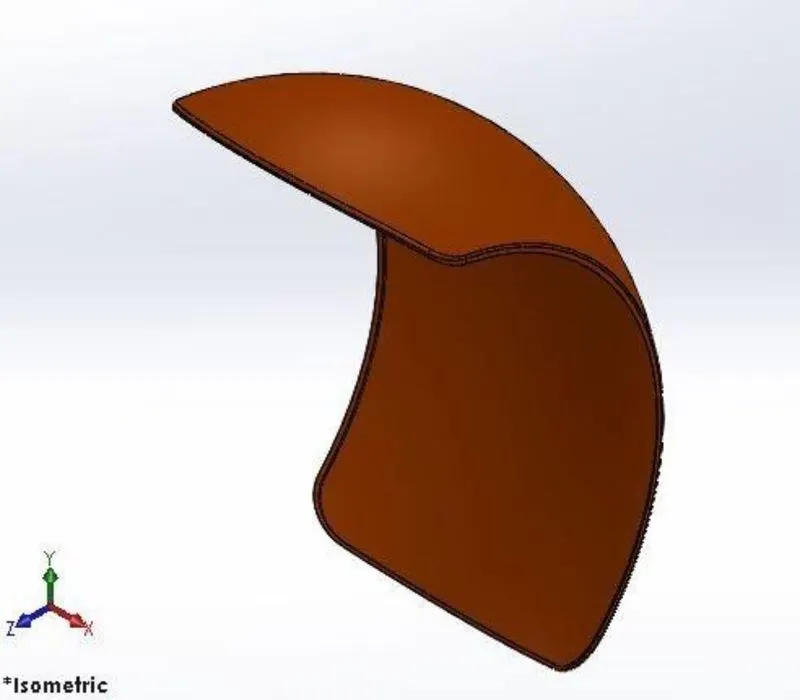
The rear fender and the front fender have the similar application. Instead, the rear fender is mounted above the chassis of the rear part which is above the rear wheel.
Features used to create Rear Fender:
- Sketch
- Offset Entities
- Trim
- Revolve
- Appearance
Oil Tank:
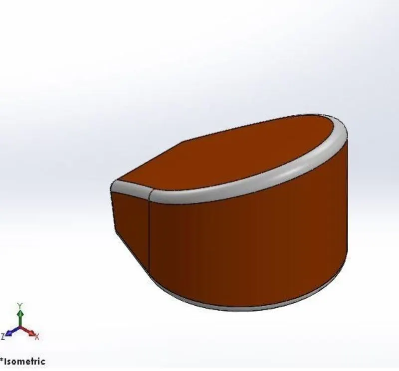
The oil tank is used to store the oil, which is required to run the engine.
Features used to create the Oil Tank:
- Sketch
- Boss Extrude
- Combine
- Fillet
- Shell
Shell:
The Shell feature is used to create a hollow interior of a model.
Here, the thickness must be defined, which is the thick ness of the casing or the walls.
Combine:
The combine feature is used to combine two bodies into one single.
Pedal:
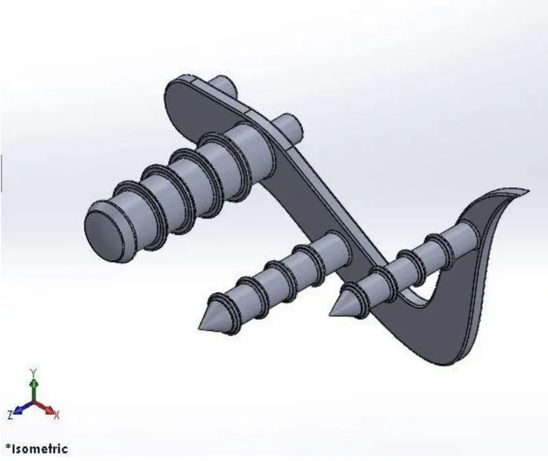
Pedal is the part attached to the chassis. As everybody already knows. The application of the pedal is to allow to rider to place the leg on it.
Features used to create the Pedal:
- Sketch
- Boss Extrude
- Fillets
- Linear Pattern
- Dome
- Chamfer
Chamfer:
The chamfer feature is used to create a beveled feature on the selected edges, faces or a vertex. The purpose of using the chamfer feature is to ease otherwise sharp edges, both for safety and to prevent damage to the edges.
Linear pattern:
The linear pattern feature is almost as similar to the curve driven pattern instead in linear pattern the features or the bodies are patterned linearly.
Rear Wheel:
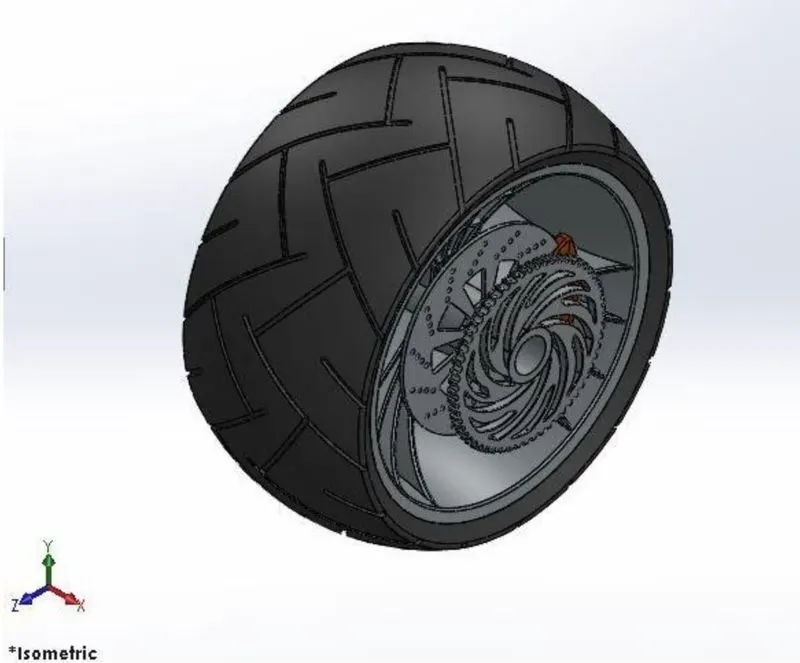
Features used to create the Front Wheel:
- Sketch
- Revolve
- Extrude Boss
- Revolve cut
- Linear Pattern
- Sketch Fillet
- Chamfer
- Fillet
- Extrude cut
- Circular Pattern
Front Wheel:
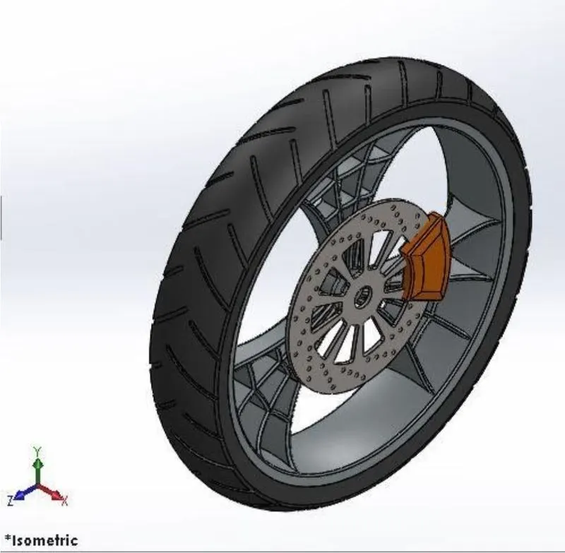
Almost the same features used to create the rear wheel are used to create the front wheel. The only difference is the dimensions of the wheel.
Front Fork:
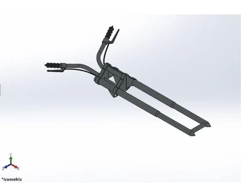
A front fork is the part of the bike that holds the front wheel and functions mainly as a shock absorber. It allows the front wheel to react based on the road features without having an adverse effect on the bike frame.
Features used to create Front fork:
- Sketch
- Boss Extrude
- Trim
- Revolve
- Split
- Dome
- Mirror
- Combine
- Projected curve
- Sweep
Projected curve:
Projected curve is the feature used to create a 3D projected curve based on 2 different 2D sketches.
Chassis:
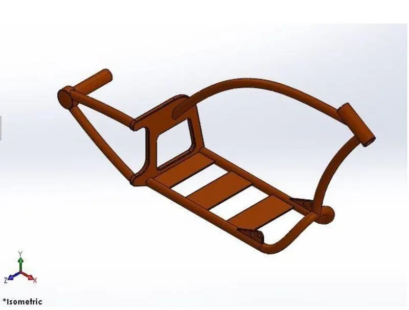
Chassis is the main frame of the bike. All the major components of the bike are attached to the chassis.
Features used to create chassis:
- Sketch
- Offset
- Convert Entities
- Projected curve
- Sweep
- Split
- Revolve
- Extrude cut
- Fillet
- Combine
Engine:
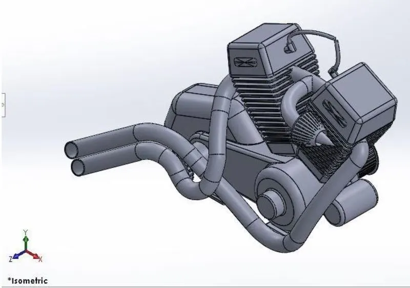
Engine is the most important component of the bike. Without the engine, the bike cannot run.
Features used to create the Engine:
- Sketch
- Revolve
- Trim
- Boss Extrude
- Cut Extrude
- Dome
- Offset
- Fillet
- Projected curve
- Composite curve
- Sweep
- Mirror
- Circular Pattern
- Split
Gas Tank:
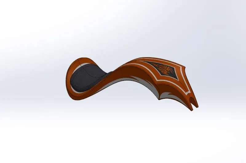
Gas tank is the part where the gas is stored and delivered to the engine when needed.
Features used to create the Gas Tank:
- Projected curve
- Sweep surface
- Lofted Surface
- Fill surface
- Trim (Surface)
- Knit
- Sweep Cut
- Fillet
Loft Surface:
Loft surface feature is used to create multiple 3D curves creating a smooth tangency between the selected curves.
Sweep Surface:
Sweep surfaces are surfaces that are generated from a section curve positioned along a path.
Surface knit:
It is used to knit two free edges of surface together.
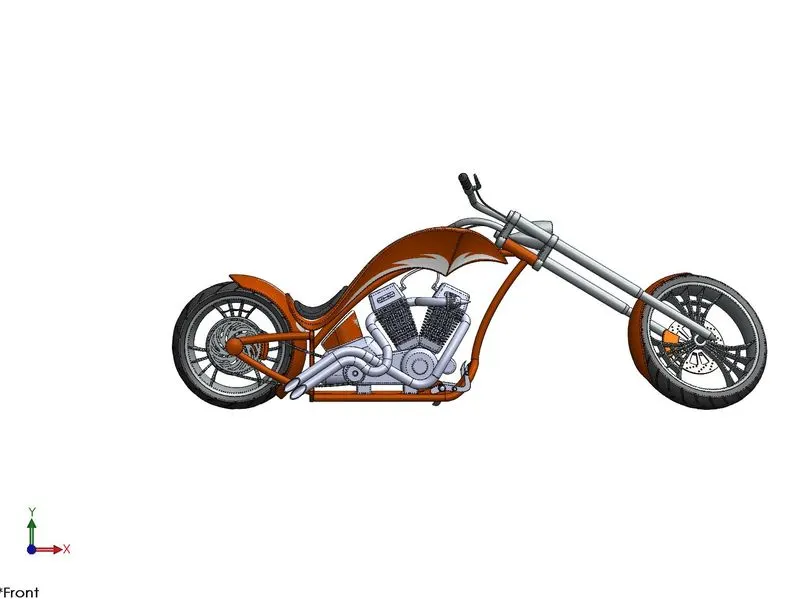
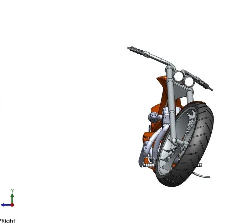
Assembly of the Chopper:
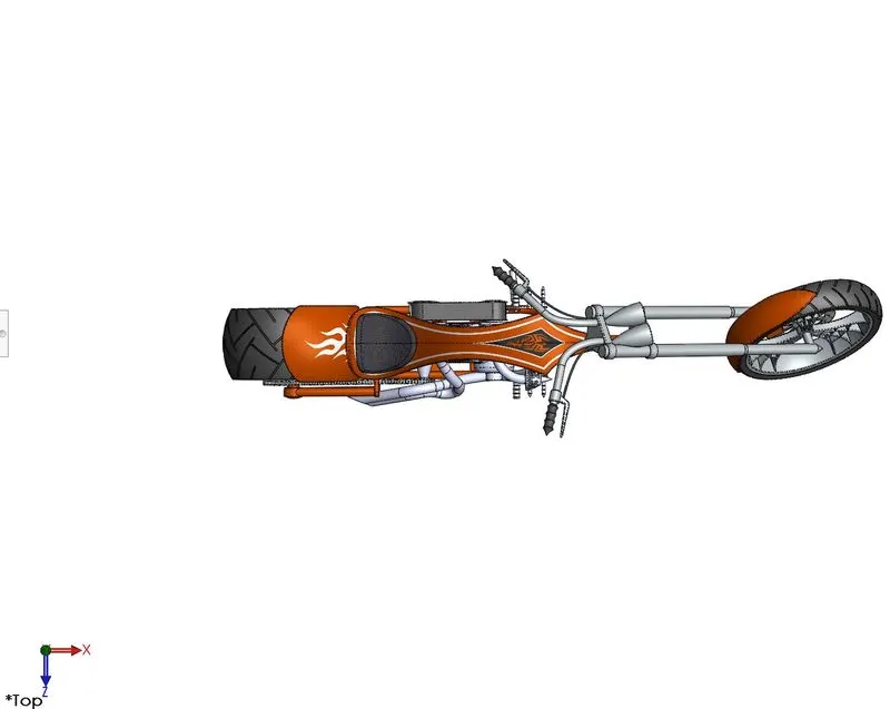
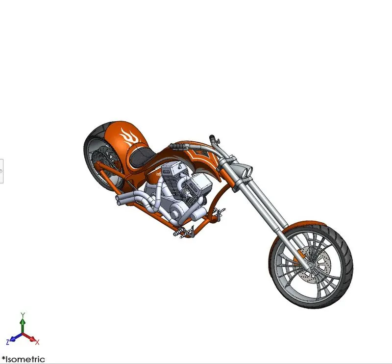
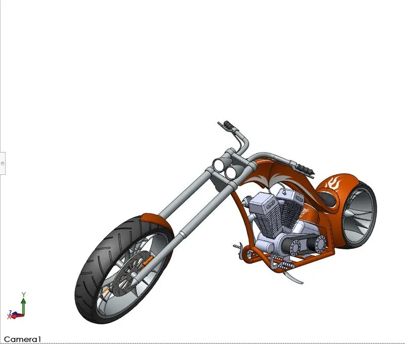
For making the assembly of the chopper, all the parts are inserted one by one and assembled with the help of corresponding mates. As, in our case, the whole assembly is framed around the chassis of the bike. Thus, the chassis part is inserted first and fixed, and all the other parts are then mated.
Rendering:
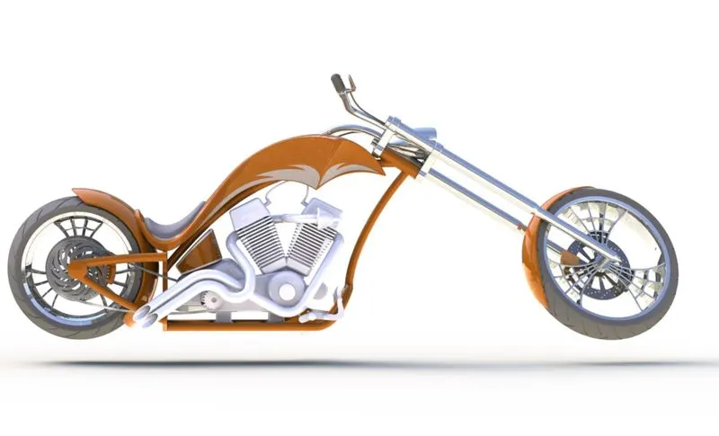
Rendering is used to create realistic images of the model. Rendering can be done either by using Photoview360 or by using Solidworks Visualize.
Photoview 360:
Photoview 360 is a rendering tool in Solidworks. It provides the user with many options such as environments and other stuff to create a realistic model of the preexisting model.
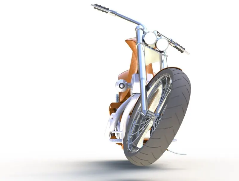
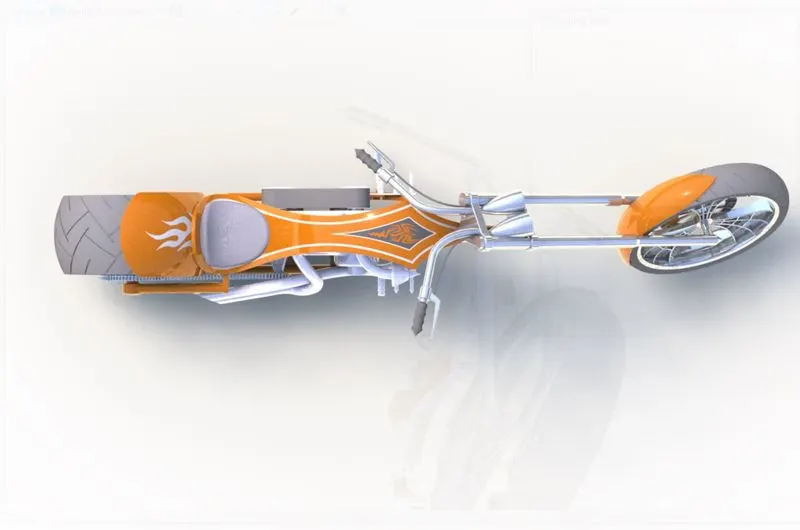
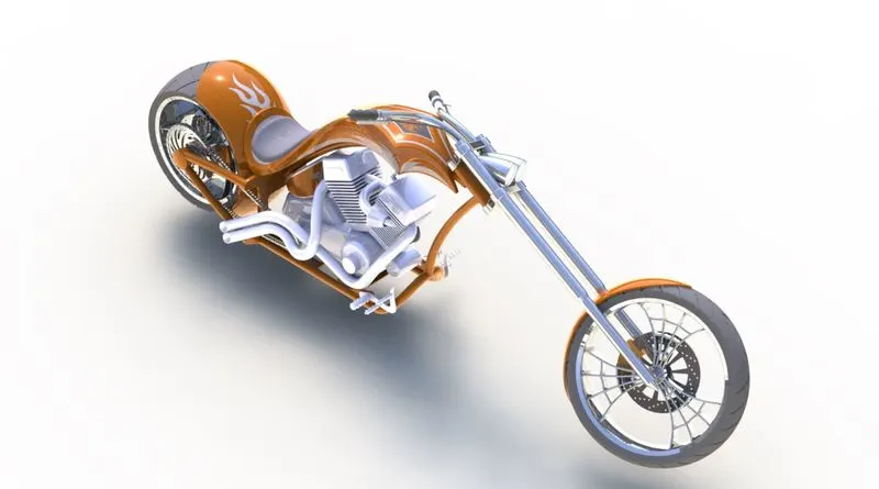
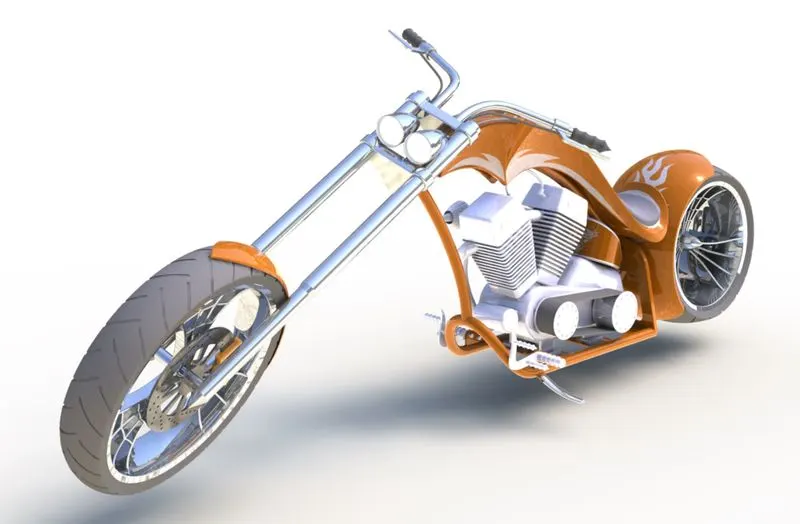
Conclusion:
- Initially all the parts are modelled.
- All the parts are then assembled using mates.
- The assembly is then rendered to give it a more realistic using rendering tools.