Photo Realistic Rendering
Objective
Use solid works to create a model of an American-style chopper. Create photoview360 renders that showcase the model and its design features. Assess the usefulness of the model and suggest improvements.
Introduction
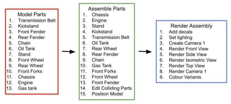
This report details the creation of a solid works model of an American-style chopper. The report begins with a flow chart of the design method. Following this are part descriptions of all components with three view images. There is an assembly description detailing the assembly process and positioning of the model. There are decal renders showcasing their details and positions. There are the renders of the model including renders in several colour variations. Finally are the conclusions, detailing the usefulness of the model and improvements that could be made.
Design method
Part Descriptions
There is a section for each part of the chopper assembly. Each section contains a step guide for creation of each part outlining sketches, features and default appearances of each part. There are three view images of the part at the bottom of each section. For ease of assembly, some part files had their planes renamed to better reflect their positions. For clarity, they have been referred to as they appear in the figures.
Transmission Belt
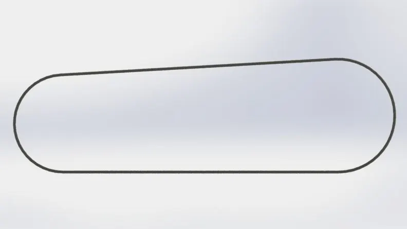
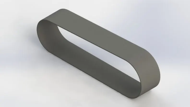
Figure 1 (images of the chain in front, side and isometric views respectively)
Transmission Belt
- Sketch1 was created using circles, lines and power trim on the front plane. It defines the front view cross section of the belt.
- Sketch1 was blind extruded 88mm from the sketch plane to create Boss-Extrude1.
- The edges of Boss-Extrude1 were symmetrically filleted 1 mm to create Fillet1.
Appearance
- A matte black rubber appearance was applied to the transmission belt.
Kick Stand
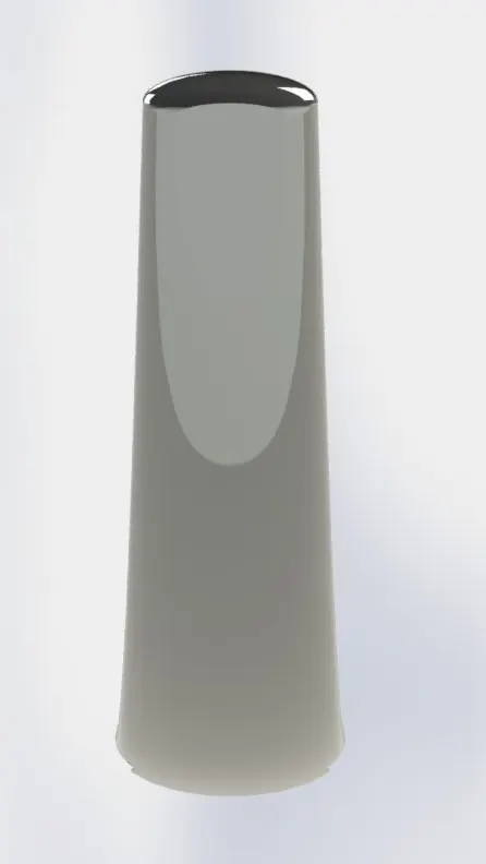
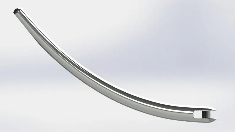
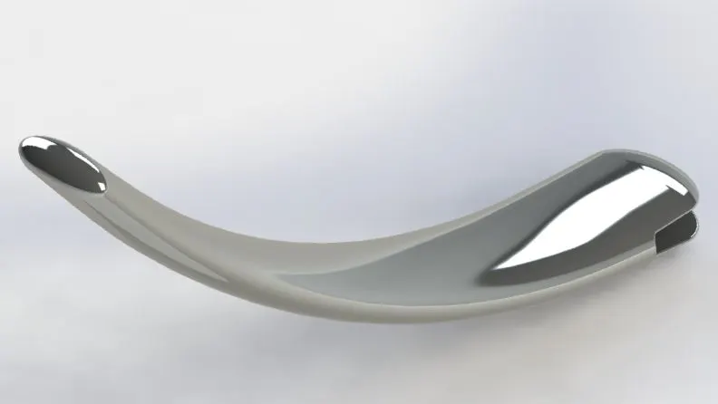
Figure 2 (images kickstand of the in front, side and isometric views respectively)
Arm
- Three sketches were created. Sketch1 and Sketch3 are ellipses drawn on the front plane. They define the front view cross section of each end of the arm. Sketch2 is a spline drawn on the right plane that defines the centre line of the stand.
- Sketches 1, 2 and 3 provided the reference geometry for Loft1.
- Elliptical domes of 13mm and 5mm were added to the larger and smaller ends of the kickstand, respectively.
Cutout
- Sketch4 is a centre point rectangle that defines the side view cross section of the cutout at the larger end of the kickstand.
- Sketch4 was through all cut-extruded to create Cut-Extrude1.
Grounding spot
- Sketch5 is a horizontal line that defines the flat spot on the smaller end of the kickstand.
- Sketch5 was used to split the kickstand with consume cut bodies on to create Split1.
- Sketch 6 is a circle drawn inside the cutout that defines the mounting pin for the kickstand.
Mounting Pin
- Sketch6 was extruded up to next to create Boss-Extrude1.
- The interior edges of the cutout were symmetrically filleted by 2 mm to create fillet1
- The exterior edges of the cutout and the mounting pin were symmetrically filleted by 0.5 mm to create Fillet2.
Appearance
- A chrome plate appearance was applied to the kickstand.
Front Fender
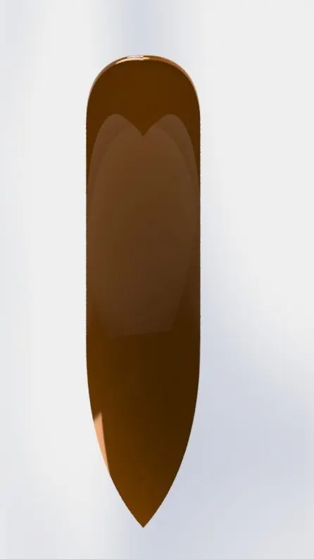
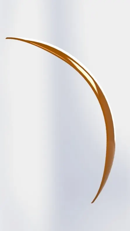
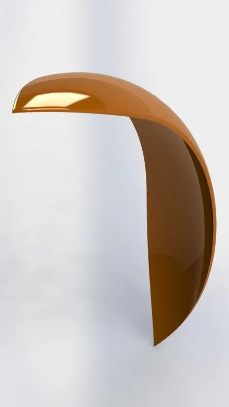
Figure 3 (images of the front fender in front, side and isometric views respectively)
Front Fender
- Sketch1 was created using circles, lines and power trim. It defines the front view cross section of the front fender
- Sketch1 was blind revolved with an offset angle of 5 degrees about the x axis through an angle of 130 degrees to create Revolve1.
- Sketches 2 and 3 were created using splines. They define the top and bottom cutoffs, respectively.
- Sketches 2 and 3 were used to split the front fender to create Splits 1 and 2, respectively.
- The edges of the front fender were symmetrically filleted by 6mm to create Fillet1.
Appearance
- A painted car sienna appearance was applied to the front fender.
Rear Fender
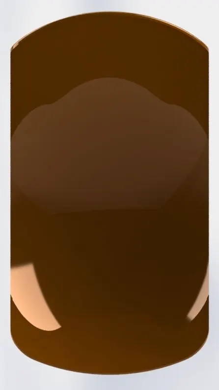
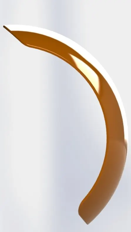
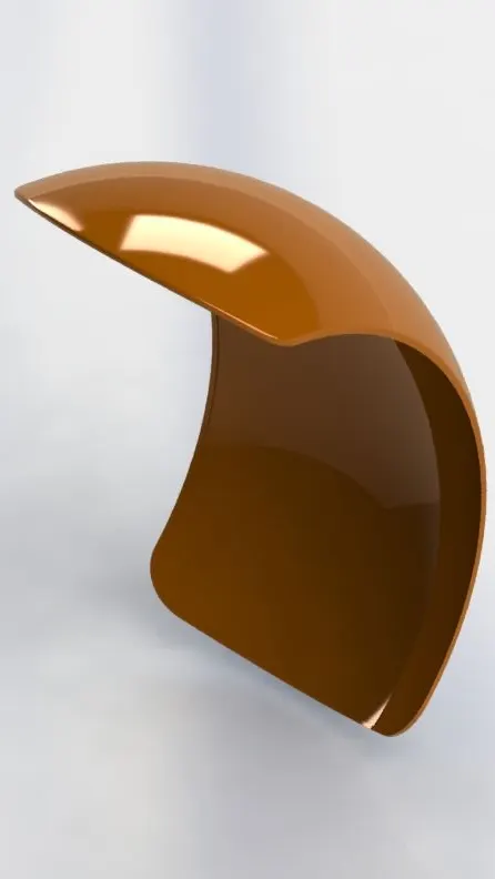
Figure 4 (images of the in front, side and isometric views respectively)
Rear Fender
- Sketch1 was created using circles, lines and power trim on the front plane. It defines the cross section of the fender
- Sketch1 was blind revolved with an offset angle of 10 degrees about the x axis through an angle of 140 degrees to create Revolve1.
- Sketch2 is an arc that defines the top cutoff.
- Sketch2 was used to split the rear fender to create Split1.
- The four corners of the rear fender were symmetrically filleted by 45mm to create Fillet1.
- The top and bottom faces of the rear fender were symmetrically filleted by 4mm to create Fillet2.
- The rear fender was shelled with a thickness of 4 mm to create Shell1.
Appearance
- A painted car sienna appearance was applied to the rear fender.
Chain
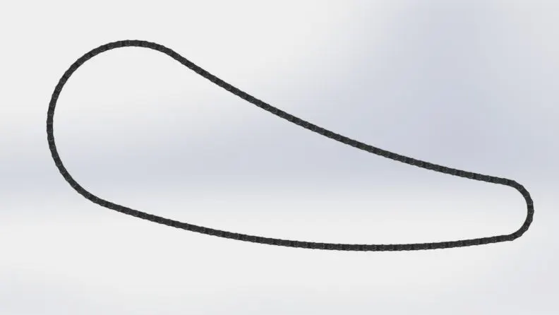
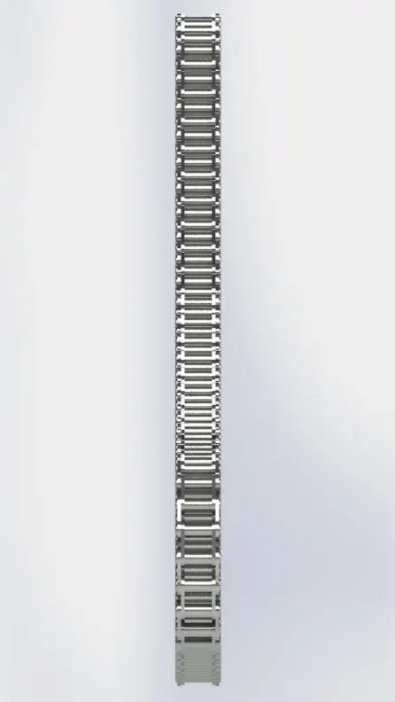
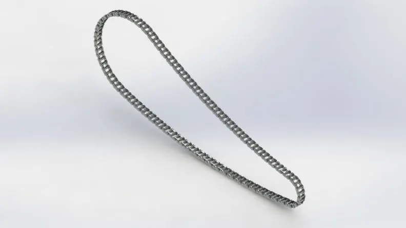
Figure 5 (images of the rear fender in front, side and isometric views respectively)
Chain
- Sketch1 was created using arcs, circles and power trim. It defines the path of the chain.
- Sketch2 was created using arcs, circles, lines and power trim. It defines the front view cross section of the two links and pins.
- Sketch2 was used to create block files for the pins and links.
- The pin cross section of Sketch2 was midplane extruded 25 mm to create Boss-Extrude1.
- The outer link cross section Sketch2 was blind extruded 2 mm with an offset of 9.5mm to create Boss-Extrude2.
- The inner link cross section Sketch2 was blind extruded 2 mm from an inside vertex of the outer link to create Boss-Extrude3.
- The edges of the pins were symmetrically filleted by 0.5 mm to create Fillet1 and Fillet2.
- Four curve patterns were created following the same process. First the block files were positioned so that the centre point of the pins was coincident with an arc from the path defined by Sketch1. The blocks were extruded as described earlier. The curve pattern was then created so that the final pin did not leave the arc it began on.
- More blocks had to be positioned manually to marry the curve patterns together.
- The inside and outside links were mirrored about mid plane to create Mirror1.
Appearance
- A chrome plate appearance was applied to the chain.
Oil Tank
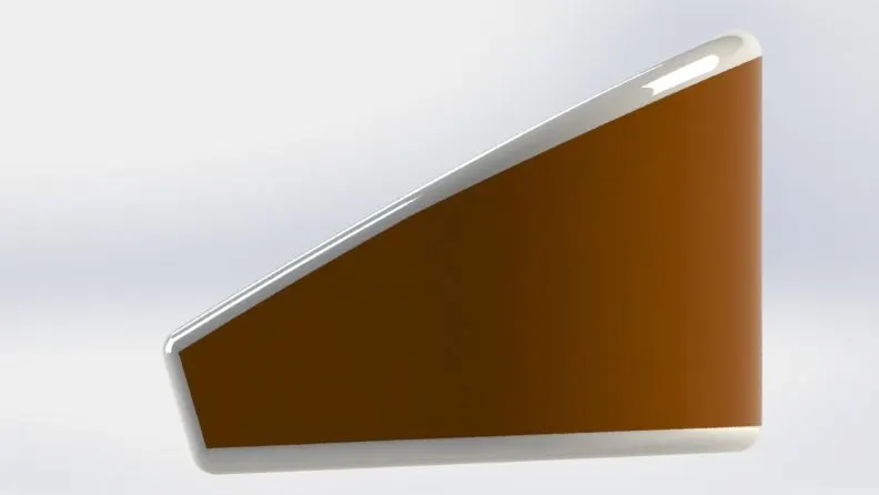
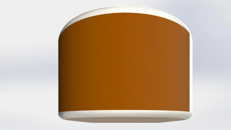
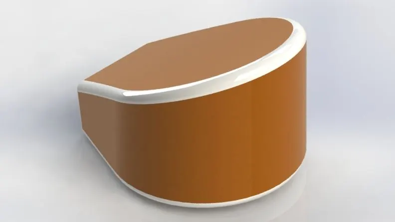
Figure 6 (images of the oil tank in front, side and isometric views respectively)
Oil Tank
- Sketch1 was created using lines and arcs. It defines the top view cross section of the gas tank.
- Sketch1 was blind extruded 170mm to create Boss-Extrude1.
- Sketch2 was created using lines and arcs. It defines the front view cross section of the gas tank.
- Sketch2 was through all extruded to create Boss-Extrude2.
- Boss-Extrude1 and Boss-Extrude2 were common combined to create combine1.
- The edges of the oil tank were symmetrically filleted by 10 mm to create Fillet1.
- The oil tank was shelled with a thickness of 3 mm to create Shell1.
Appearance
- A sienna painted car appearance was applied to the oil tank.
- A white painted car appearance was applied to the Filet1 of the oil tank.
Stand
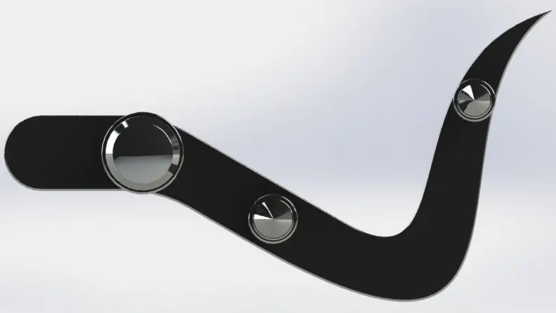
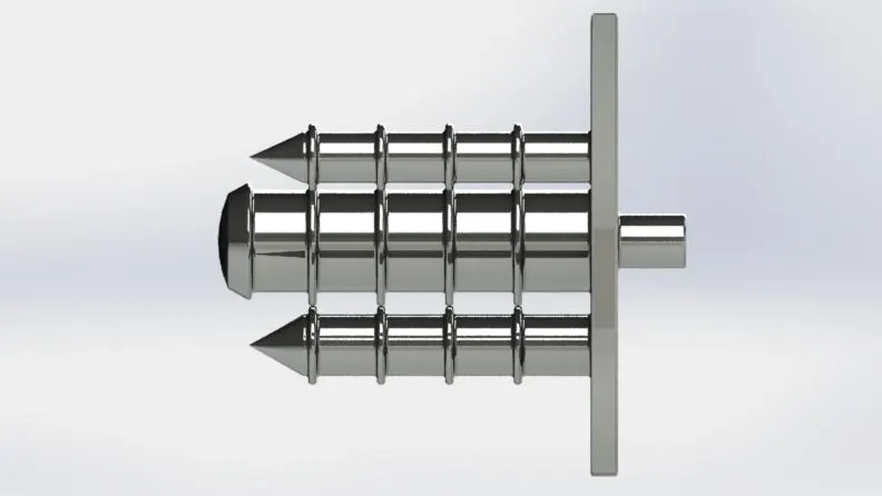
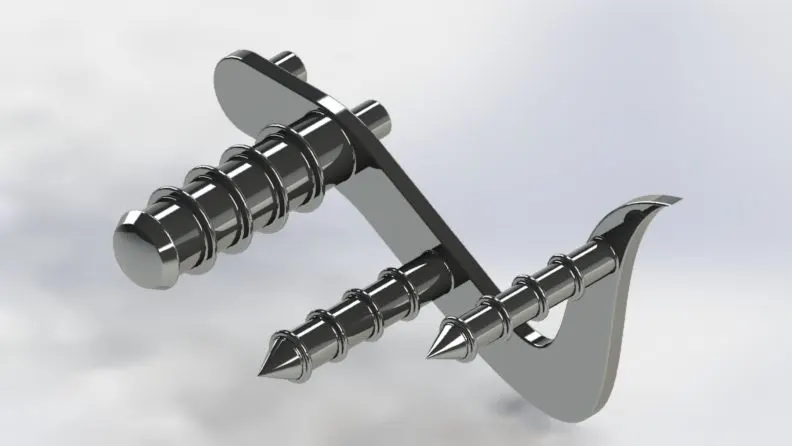
Figure 7 (images of the stand in front, side and isometric views respectively)
Plate
- Sketch1 was created using splines, arcs and lines. It defines the front view cross section of the main body of the stand.
- The plate cross section of Sketch1 was blind extruded 8 mm to create Boss-Extrude1.
Mounting Pins
- The mounting pin cross section of Sketch1 was blind extruded 20 mm in the opposite direction to create Boss-Extrude2.
- The outside edges of the plate and the edges where the mounting pins meet the plate were symmetrically filleted by 1 mm to create Fillet1.
Foot Pegs
- Sketch2 was created using lines. It defines the half side view cross section of the rear foot peg.
- Sketch2 was blind revolved about the axis through an angle of 360 degrees to create Revolve1.
- A non elliptical dome of 3mm was added to the end of the back foot peg.
- The two furthest edges of the rear foot peg, and the outside edges of the mounting pins were symmetrically filleted by 1 mm to create Fillet2.
- The mid and front foot peg cross sections of sketch1 were extruded 100mm to create Boss-Extrude3.
- An asymmetric distance-distance chamfer of 16 and 9 mm was added to the end of the mid foot peg.
- An asymmetric distance-distance chamfer of 16 and 7.5 mm was added to the end of the front foot peg.
- Sketch3 was created using circles. It defines the front plane cross section of the grips.
- Sketch3 was blind extruded 2.5 mm with an offset of 20 mm to create Boss-Extrude4.
- The edges of the grips were symmetrically filleted by 1 mm to create Fillet3.
- Boss-Extrude4 was patterned linearly 4 times with a spacing of 20 mm to create LPattern1.
- The edges where the foot pegs meet the plate and edges where the foot peg cylinders meet their end caps were symmetrically filleted by 1 mm to create Fillet4.
Appearance
- A chrome plate appearance was applied to the stand.
Front Wheel
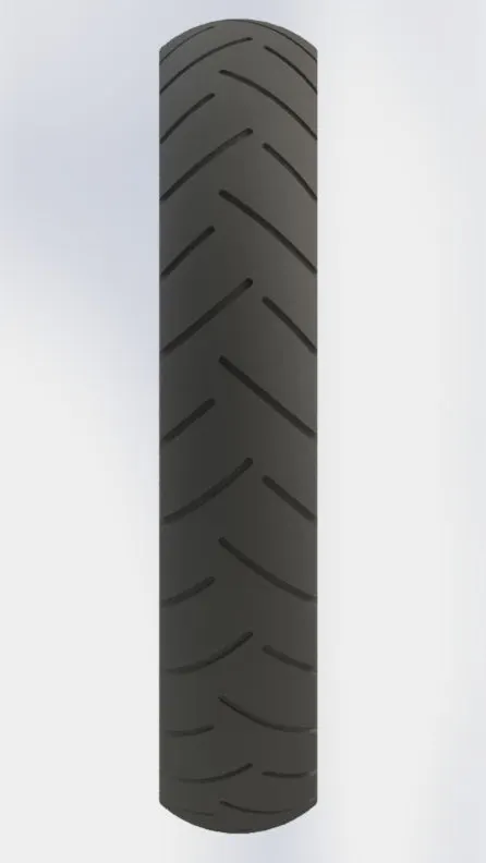
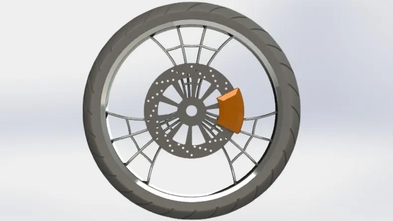
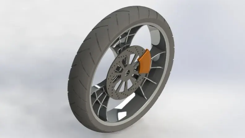
Figure 8 (images of the front wheel in front, side and isometric views respectively)
Rim, Hub & Spokes
- Sketch1 was created using lines and arcs. It defines the front view cross section of the hub and the rim.
- Sketch1 was blind revolved with about the x axis through an angle of 360 degrees to create Revolve1.
- Sketch2 was created using splines, lines and arcs. It defines the side view cross section of the spokes.
- Sketch2 was midplane extruded 122 mm to create Boss-Extrude1.
- Sketch3 was created using splines and arcs. It defines the side cross section of the cutouts of the spokes.
- Sketch3 was through all - both cut-extruded to create Cut-Extrude1
- Sketch4 was created using arcs and lines. It defines the side view cross section of the webbing of the spokes.
- Sketch4 was up to vertex extruded using left and right most vertices of the spoke to create Boss-Extrude2.
- Sketch5 was created using splines and lines. It defines the front view cross section of the spokes and the hub.
- Sketch5 was blind cut-revolved about the x axis through an angle of 360 degrees to create Cut-Revolve1.
- The spoke was patterned about the x axis 3 times through an angle of 360 degrees to create CirPattern1.
- The hub, spokes and rim were add combined to create Combine1.
- The edges of the spokes and hub were symmetrically filleted by 4 mm to create Fillet1.
Rotor
- Sketch6 was created using a circle. It defines the side view cross section of the rotor.
- Sketch6 blind extruded 7 mm with an offset of 45 mm to create Boss-Extrude3.
- Sketch7 was created using circles and linear patterns. It defines the side view cross section of the circular rotor cutouts.
- Sketch7 was through all cut-extruded on the rotor to create Cut-Extrude2.
- Cut-Extrude2 was patterned about the x axis 14 times through an angle of 360 degrees to create CirPattern2.
- Sketch8 was created using lines and arcs. It defines the side view cross section of the trapezoidal rotor cutouts.
- Sketch8 was through all cut-extruded on the rotor to create Cut-Extrude3.
- The inside edges of the trapezoidal rotor cutout were symmetrically filleted by 5 mm to create Fillet2.
- Cut-Extrude3 and Fillet2 were patterned about the x axis 10 times through an angle of 360 degrees to create CirPattern3.
Axle Shaft
- Sketch9 was created using a circle. It defines the side view cross section of the axle shaft.
- Sketch9 was through all - both cut-extruded to create Cut-Extrude4.
Calliper
- Sketch10 was created using arcs and lines. It defines the side view cross section of the calliper.
- Sketch10 was blind extruded from the inside face of the rotor 19.5 mm in direction 1 and 10.5 mm in direction 2 to create Boss-Extrude4.
- An asymmetric distance-distance chamfer of 20 and 6 mm was added to the outside face of the calliper to create Chamfer1.
- An asymmetric distance-distance chamfer of 6 and 20 mm was added to the inside face of the calliper to create Chamfer2.
- The top and bottom edges of the calliper were symmetrically filleted by 8 mm to create Fillet3.
- The inside edges of Chamfer1 and Chamfer2 were symmetrically filleted by 4 mm to create Fillet4.
Tyre
- Sketch11 was created using convert entities, lines and arcs. It defines the front view cross section of the tyre.
- Sketch11 was blind revolved about the x axis through an angle of 360 degrees to create Revolve2.
- Sketch12 was created using rectangles. It defines the front view cross section of the tyre tread.
- Sketch12 was offset from surface cut-extruded from the surface of the tyre with an offset value of 450 mm, a distance of 4 mm to create Cut-Extrude5.
- The ends of the tyre treads were face filleted to create Fillets 5, 6, 7 and 8.
- Cut-Extrude5 and Fillets 5, 6, 7 and 8 was patterned about the x axis 14 times through an angle of 360 degrees to create CirPattern4.
Appearance
- A painted car sienna appearance was applied to the front wheel calliper.
- A chrome plate appearance was applied to the front wheel rim and rotor.
Rear Wheel
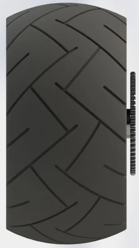
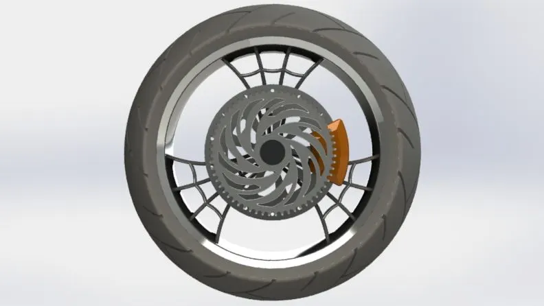
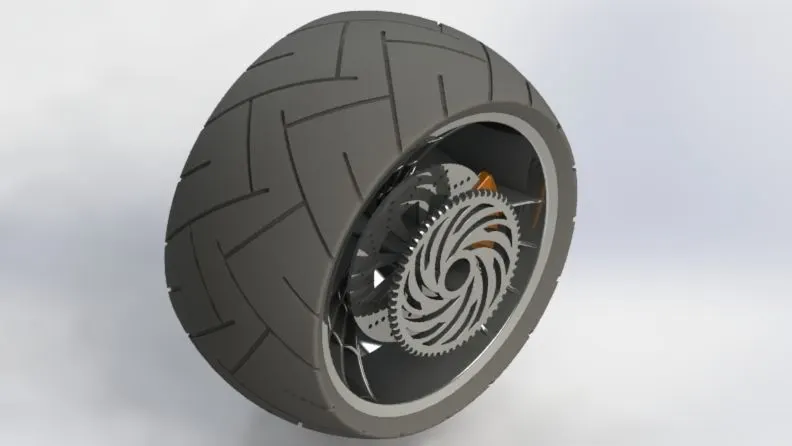
Figure 9 (images of the rear wheel in front, side and isometric views respectively)
Rim, Hub & Spokes
- Sketch1 was created using lines and arcs. It defines the front view cross section of the hub and the rim.
- Sketch1 was blind revolved with about the x axis through an angle of 360 degrees to create Revolve1.
- Sketch2 was created using splines, lines and arcs. It defines the side view cross section of the spokes.
- Sketch2 was midplane extruded 300 mm to create Boss-Extrude1.
- Sketch3 was created using splines and arcs. It defines the side cross section of the cutouts of the spokes.
- Sketch3 was through all - both cut-extruded to create Cut-Extrude1.
- Sketch4 was created using arcs and lines. It defines the side view cross section of the webbing of the spokes.
- Sketch4 was up to vertex extruded using left and right most vertices of the spoke to create Boss-Extrude2.
- The spoke was patterned about the x axis 3 times through an angle of 360 degrees to create CirPattern1.
- The hub, spokes and rim were add combined to create Combine1.
- Sketch5 was created using splines and lines. It defines the front view cross section of the spokes and the hub.
- Sketch5 was blind cut-revolved about the x axis through an angle of 360 degrees to create Cut-Revolve1.
- The edges of the spokes and hub were symmetrically filleted by 3 mm to create Fillet1.
Axle shaft
- Sketch6 was created using a circle. It defines the side view cross section of the axle shaft.
- Sketch6 was through all - both cut-extruded to create Cut-Extrude2.
- Sketch7 was created using lines. It defines the axle hub front view cross section.
- Sketch7 was blind revolved about the x axis through an angle of degrees to create Revolve2.
Rotor
- Sketch8 was created using a circle. It defines the side view cross section of the rotor.
- Sketch8 blind extruded 7 mm with an offset of 105 mm to create Boss-Extrude3.
- Sketch9 was created using circles and linear patterns. It defines the side view cross section of the circular rotor cutouts.
- Sketch9 was through all cut-extruded on the rotor to create Cut-Extrude3.
- Cut-Extrude3 was patterned about the x axis 14 times through an angle of 360 degrees to create CirPattern2.
- Sketch10 was created using lines and arcs. It defines the side view cross section of the trapezoidal rotor cutouts.
- Sketch10 was through all cut-extruded on the rotor to create Cut-Extrude4.
- The inside edges of the trapezoidal rotor cutout were symmetrically filleted by 5 mm to create Fillet2.
- Cut-Extrude4 and Fillet2 were patterned about the x axis 9 times through an angle of 360 degrees to create CirPattern3.
Calliper
- Sketch11 was created using arcs and lines. It defines the side view cross section of the calliper.
- Sketch11 was mid plane extruded with an offset of 3.5 mm a distance of 30 mm to create Boss-Extrude4.
- An asymmetric distance-distance chamfer of 20 and 6 mm was added to the outside face of the calliper to create Chamfer1.
- An asymmetric distance-distance chamfer of 6 and 20 mm was added to the inside face of the calliper to create Chamfer2.
- The top and bottom edges of the calliper were symmetrically filleted by 8 mm to create Fillet3.
- The inside edges of Chamfer1 and Chamfer2 were symmetrically filleted by 4 mm to create Fillet4.
Sprocket
- Sketch12 was created using circles. It defines the side view cross section of the spocket.
- Sketch12 was blind extruded 15mm to create Boss-Extrude5.
- A angle distance chamfer of 45 degrees and 4 mm was added to the cylindrical face of the sprocket.
- Sketch13 was created using arcs and lines. It defines the side view sprocket tooth profile.
- Sketch13 was up to next cut-extruded to create Cut-Extrude5.
- The sprocket tooth edges were symmetrically filleted by 2.2 mm to create Fillet5.
- The sprocket tooth was patterned about the x axis 60 times through an angle of 360 degrees to create CirPattern4.
- Sketches 14 and 15 were created using arcs and lines. They define the larger and smaller of the sprocket cut outs, respectively.
- Sketches 14 and 15 were through all cut-extruded selecting only the sprocket to create Cut-Extrude 6 and 7.
- The edges where the sprocket cutouts meet the flat faces of the sprocket were symmetrically filleted by 1 mm to create Fillet6
- Cut-Extrude 6 and 7, and Fillet6 were patterned about the x axis 7 times through an angle of 360 degrees to create CirPattern5.
Tyre
- Sketch16 was created using convert entities, lines and arcs. It defines the front view cross section of the tyre.
- Sketch16 was blind revolved about the x axis through an angle of 360 degrees to create Revolve3.
- Sketch17 was created using rectangles. It defines the front view cross section of the tyre tread.
- Sketch17 was offset from surface cut-extruded from the surface of the tyre with an offset value of 400 mm, a distance of 6 mm to create Cut-Extrude8.
- The ends of the tyre treads were symmetrically filleted 4mm to create Fillets7.
- Cut-Extrude8 and Fillets 7 were patterned about the x axis 14 times through an angle of 360 degrees to create CirPattern6.
Appearance
- A painted car sienna appearance was applied to the rear wheel calliper.
- A chrome plate appearance was applied to the rear wheel rim, rotor and sprocket.
Front Forks
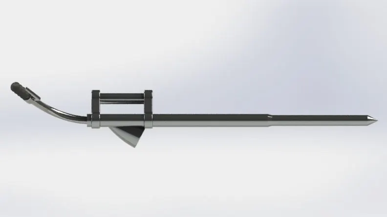
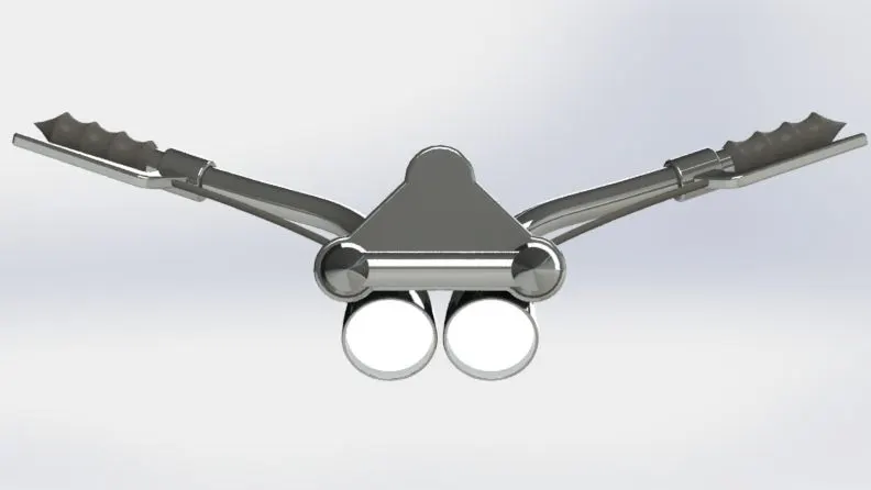
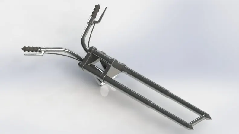
Figure 10 (images of the front forks in front, side and isometric views respectively)
Tubes
- Sketch1 was created using lines one the front plane. It defines the front view half cross section of the tubes.
- Sketch1 was blind revolved about the x axis through an angle of 360 degrees to create Revolve1.
Tri-Clamps & Axle
- Sketch2 was created using circles, lines and power trim on the right plane. It defines the half side view cross section of the tri-clamps.
- Sketch2 was blind extruded from the right plane 40 mm with an offset of 20mm to create Boss-Extrude1.
- The outside edges of the tri-clamp were symmetrically filleted by 5 mm to create Fillet1.
- The tri-clamp was patterned linearly 2 times with a spacing of 240 mm along the x axis.
- Sketch3 was created using a circle on the front plane. It defines the cross section of the axle.
- Sketch3 was extruded from the sketch plane to the tube surface to create Boss-Extrude2.
- Sketch4 was created using circles, lines and power trim on the right most face of the left tri-clamp. It defines the half side view cross section of the tri-clamp connector tube.
- Sketch4 was up to next extruded from the sketch plane to create Boss-Extrude3.
Light Bucket
- Sketch5 was created using splines and lines on the front plane. It defines the half front view cross section of the light bucket.
- Sketch5 was blind revolved about the x axis through an angle of 360 degrees to create Revolve2.
- Sketch6 was created using a circle using the right most face of the light bucket as the sketch plane. It defines the face-on cross section of the lens.
- Sketch6 was blind cut-extruded 10mm with a 5 degree draft on the sketch plane to create Cut-Extrude1.
- The outside edge of the lightbulb rim was symmetrically filleted by 3 mm to create Fillet3.
- A non-elliptical dome of 7 mm was added to the face of the lens.
- The inside edge of the light bucket rim was symmetrically filleted by 1 mm to create Fillet4.
- Sketch7 was created using lines on the front plane. It defines the front view cross section of the lens frame.
- Sketch7 was blind cut-revolved about the light bucket axis through an angle of 360 degrees to create Cut-Revolve1.
- The light bucket was translated along the z axis -48 mm to create Body-Move/Copy1.
Handlebars
- Sketch8 was created using a circle on the flat end of the tube. It defines the cross section of the handle bars.
- Sketch9 was created using a line and a spline on the top plane. It defines the top view path of the handlebars.
- Sketch10 was created using a spline on the front plane. It defines the front view path of the handlebars.
- Sketch 9 and 10 were combined to create a composite curve called Curve1.
- Sketch8 was swept along the path of Curve1 to create Sweep1.
Grips
- Sketch11 was created using convert entities and lines on the end face of the handle bars. It defines the cross section of the angle at which Plane1 is.
- The end face of the handlebars and Sketch11 were referenced to create Plane1.
- Sketch13 was created using arcs and lines on Plane1. It defines the cross section of the grips .
- Sketch13 was blind revolved about the handlebar centre line through an angle of 360 degrees to create Revolve3.
Brake levers
- Sketch12 was created using a rectangle on Plane1. It defines the cross section of the brake lever mount.
- Sketch12 was blind revolved about the handlebar centre line through an angle of 360 degrees to create Revolve4.
- Plane1 offset 160 degrees and the centre line of the grips were referenced to create Plane2.
- Sketch14 was created using lines on the Plane2. It defines the cross section of the brake levers.
- Sketch14 was mid plane extruded 15 mm on the sketch plane to create Boss-Extrude4.
- The outside shoulder edge of the brake lever was symmetrically filleted by 25 mm to create Fillet5.
- The inside shoulder edge of the brake lever was symmetrically filleted by 5 mm to create Fillet6.
- The other edges of the lever and the outside edges of the brake lever mount were symmetrically filleted by 4 mm to create Fillet7.
Brake Lines
- Sketch15 was created using circle on the relevant face of the brake lever. It defines the cross section of the brake lines.
- Sketch16 was created using spline on the top plane. It defines the top view path of the brake line .
- Sketch17 was created using spline on the right plane. It defines the side view path of the brake line.
- Sketch 16 and 17 were combined to create a composite curve called Curve2.
- Sketch15 was swept along the path of Curve2 to create Sweep2.
Mirroring
- The flat face of the tri-clamp was referenced to create a plane called Fork Midlane.
- Fork Midplane was referenced for a mirror of all components to create Mirror1.
- The tube and the tube mirror were add combined to create Combine1.
- The tri-clamp and the tri-clamp mirror were add combined to create Combine2.
Viewing
- A simple sketch was created coinciding with the axle axis.
- The top plane with an offset of 59 degrees and the simple sketch were used to create Vertical Plane Front Fork
Appearance
- A chrome plate appearance was applied to the tubes, handles, light buckets and tri-clamps.
- A glossy black rubber appearance was applied to the grips and the brake lines.
- In one variation clear glass appearance was applied to the lens of the light bucket
- In another variation light appearance was applied to the lens of the light bucket
Chassis
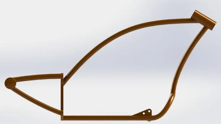
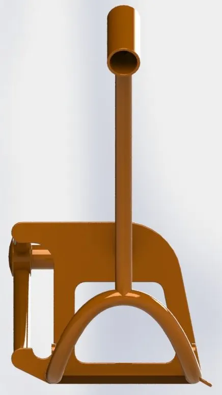
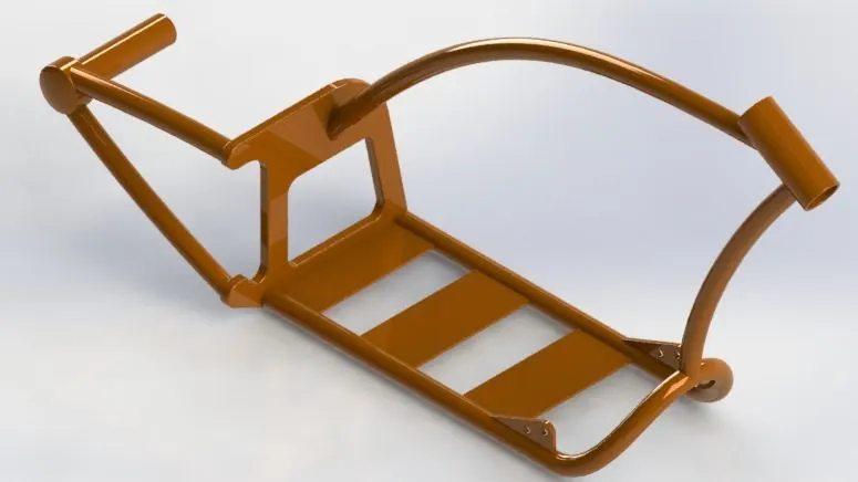
Figure 11 (images of the chassis in front, side and isometric views respectively)
Lower Tubes
- Sketch1 was created using a blueprint image of the chopper on the front plane.
- Sketch2 was created using circles on the front plane. It defines the front view cross section of the lower tubes.
- Sketch3 was created using a spline and a line on the front plane. It defines the front view path of the lower tubes.
- Sketch4 was created using a spline and a line on the top plane. It defines the top view path of the lower tubes.
- Sketches 3 and 4 were combined to create a composite curve called Curve1.
- Sketch5 was created using splines on the right plane. It defines the path of the side view path of the lower tubes.
- Sketch6 was created using spline and a line on the front plane. It defines the front view path of the lower tubes.
- Sketches 5 and 6 were combined to create a composite curve called Curve2.
- Sketch was swept along the path of Curve2 to create Sweep1.
- The forward lower tube was mirrored about the front plane to create Mirror1.
Plate
- Sketch7 was created using circles lines and power trim on the right plane. It defines the side view cross section of the plate.
- Sketch was blind extruded 22mm on the sketch plane to create Boss-Extrude1.
- Sketch8 was created using lines on the right plane. It defines the cross section of the plate cutout.
- Sketch8 was up to next cut-extruded on the sketch plane to create Cut-Extrude1.
- An asymmetric chamfer of 90 and 44 mm was added to the lowest edge of the plate to create Chamfer1.
- The edges of the cutout and the edges on the rear tube attachment points were symmetrically filleted by 25 mm to create Fillet1.
- The edges between the main plate and the rear tube attachment points were symmetrically filleted by 50 mm to create Fillet2.
Rear Tubes
- The front plane and a vertex of the rear tubes mounting point were referenced to create Plane1.
- Sketch9 was created using circle on the face of the plate. It defines the cross section of the upper rear tube.
- Sketch10 was created using spline on the front plane. It defines the path of the upper rear tube.
- Sketch9 was swept along the path Sketch10 to create Sweep2.
- Sketch11 was created using spline on the front plane. It defines the path of the lower rear tube.
- Sketch12 was created using spline on the front plane. It defines the path of the lower rear tube.
- Sketch11 was swept along the path of Sketch12 to create Sweep3.
Axle
- Sketch13 was created using circle on Plane1. It defines the front view cross section of the axle hub.
- Sketch13 was mid plane extruded 44 mm on the sketch plane to create Boss-Extrude2.
- Sketch14 was created using a circle on the inside face of the axle hub. It defines the front view cross section of the axle.
- Sketch14 was blind extruded 223 mm on the sketch plane to create Boss-Extrude3.
- A non-elliptical dome of 10 mm was added to the outside face of the axle hub.
Upper Tubes
- Sketch15 was created using splines on the front plane. It defines the path of the upper tube.
- Sketch16 was created using circles on the end vertex of Sketch15. It defines the cross section of the upper tube.
- The end point and spline of Sketch15 were referenced to create Plane2.
- Sketch16 was swept along the path of Sketch15 to create Sweep4.
- The face of the plate was used to split the upper tube to create Split1.
Front Tubes
- Sketch17 was created using a spline on the front plane. It defines the path of the front tube.
- The midpoint of Sketch2 and the spline of Sketch17 were referenced to create Plane3.
- Sketch18 was created using circles on Plane3. It defines the cross section of the front tube.
- Sketch18 was swept along the path of Sketch17 to create Sweep5.
- The face of the lower tube was used to split the front tube to create Split2.
- All solid bodies were combined to create Combine1.
Fork Mount
- Sketch19 was created using lines on the front plane. It defines the half front view cross section of the fork mount.
- Sketch19 was blind revolved about the mid line through an angle of 360 degrees to create Revolve1.
- The face of the fork mount split the front tubes to create Split3.
- All solid bodies were combined to create Combine2.
- The edges of the fork mount and the edges where the fork mount meets the front and upper tubes were symmetrically filleted by 2 mm to create Fillets 3 and 4.
Engine Mount
- Sketch20 was created using rectangles on the front plane. It defines the front view cross section of the engine mount.
- Sketch20 was up to next extruded on the sketch plane to create Boss-Extrude4.
Stand Mounts
- Sketch21 was created using lines and circles on the front plane. It defines the front view cross section of the Stand mounts.
- Sketch21 was mid plane extruded 10 mm with an offset of 165 m on the sketch plane to create Boss-Extrude5.
- The face of the lower tube split the stand to create Split4.
- The top edge of the stand mount was symmetrically filleted by 20 mm to create Fillet5.
- The edges of the stand mount were symmetrically filleted by 1 mm to create Fillet6.
- The stand mount was mirrored about the front plane to create Mirror2.
- All solid bodies were combined to create Combine3.
Kickstand Mount
- Sketch22 was created using a rectangle on the right plane. It defines the side view cross section of the of the kickstand mount.
- Sketch22 was blind extruded 40 mm on the sketch plane to create Boss-Extrude6.
- The square end of the kickstand mount was three face filleted by to create Fillet7.
- All edges of the kickstand were symmetrically filleted by 3 mm to create Fillet8.
- Sketch23 was created using a circle on the face of the kickstand mount. It defines the cross section of the cutout.
- Sketch23 was up to next cut-extruded on the sketch plane to create Cut-Extrude2.
- The top plane with an offset of 308 mm was referenced to create Bottom Plane Fuel Tank.
Chain Cutout
- Sketch24 was created using convert entities and an arc on the face of the plate. It defines the right view cross section of the chain cutout.
- Sketch 24 split the plate to create Split5.
- The edges of the cutout were symmetrically filleted by 3 mm to create Fillet9.
Appearance
- A painted car sienna appearance was applied to the chassis.
Engine
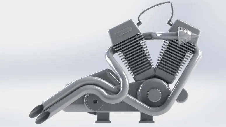
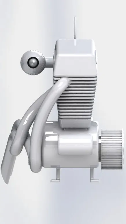
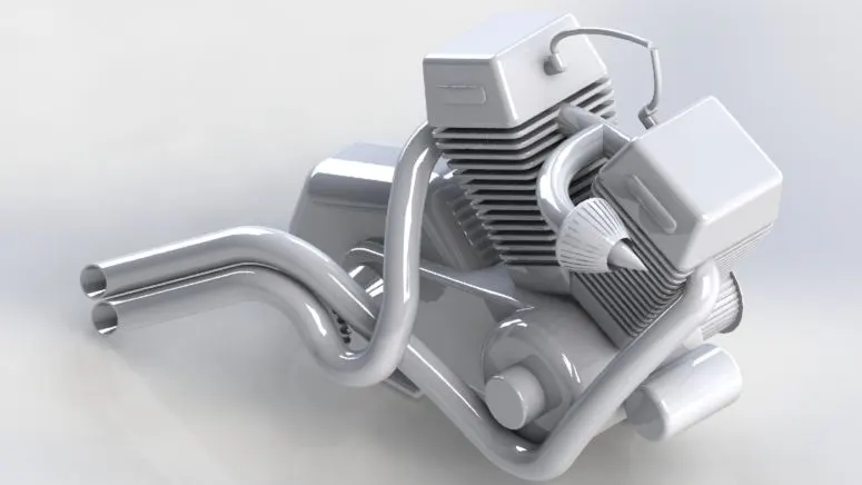
Figure 12 (images of the engine in front, side and isometric views respectively)
Casing
- Blue Print Engine was created using a blueprint image on the front plane.
- Sketch1 was created using circles and lines on the front plane. It defines the front view cross section of the lower casing.
- Sketch1 was mid plane extruded 200mm on the sketch plane to create Boss-Extrude1.
- The larger circle of Sketch1 was blind extruded 50 mm from the face of Boss-Extrude1 to create Boss-Extrude2.
- The smaller circle of Sketch1 was blind extruded 40 mm from the face of Boss-Extrude2 to create Boss-Extrude3.
- Sketch2 was created using lines on the front plane. It defines the front view cross section of the upper casing.
- Sketch2 was mid plane extruded 150 mm on the sketch plane to create Boss-Extrude4.
- The edges of the rear casing were symmetrically filleted by 50 mm to create Fillet1.
- The round edge and tangential edges of the lower casing were symmetrically filleted by 10 mm to create part of Fillet5.
- The edge between Boss-Extrude1 and 2 was symmetrically filleted by 5 mm to create part of Fillet6.
- The round edge of Boss-Extrude1 was symmetrically filleted by 25 mm to create Fillet10.
- The round edge of Boss-Extrude2 was symmetrically filleted by 4 mm to create Fillet11.
- The edge between the upper and lower casing was symmetrically filleted by 2 mm to create Fillet13.
Belt Drive Gears
- Sketch3 was created using lines on the right plane. It defines the half side view cross section of the small belt drive gear.
- Sketch3 was blind revolved about the midline through an angle of 360 degrees to create Revolve1.
- The right plane and a vertex from the rear of the lower casing were referenced to create Plane1.
- Sketch4 was created using lines on plane1. It defines the half side view cross section of the larger belt drive gear.
- Sketch was revolved about the x axis through an angle of 360 degrees to create Revolve2.
- Sketch5 was created using a rectangle on the inside face of the smaller belt drive gear rim. It defines the front view cross section of the smaller belt drive gear teeth.
- Sketch5 was up to surface extruded on the sketch plane to create Boss-Extrude5.
- Boss-Extrude5 was patterned about a cylindrical face of the smaller belt drive gear 40 times through an angle of 360 degrees to create CirPattern1.
- Sketch6 was created using a rectangle on the inside face of the larger belt drive gear rim. It defines the front view cross section of the larger belt drive gear teeth.
- Sketch6 was up to surface extruded on the sketch plane to create Boss-Extrude6.
- Boss-Extrude6 was patterned about a cylindrical face of the smaller belt drive gear 44 times through an angle of 360 degrees to create CirPattern2.
- A dome of 10 mm was added to the circular faces of both belt drive gears to create Dome1.
- Sketch7 was created using circles on the circular face of the smaller belt drive gear. It defines the front view cross section of the indents on the smaller belt drive gear.
- Sketch7 was cut-extruded on the sketch plane to create Cut-Extrude1.
- Sketch8 was created using circles on the circular face of the larger belt drive gear. It defines the front view cross section of the indents on the larger belt drive gear.
- Sketch8 was cut-extruded on the sketch plane to create Cut-Extrude2.
- An angle distance chamfer of 45 degrees and 3 mm was added to Dome1 to create Chamfer1.
- The edges of the circular faces of the belt drive gears were symmetrically filleted by 1 mm to create Fillet2.
Gearbox
- Sketch9 was created using circles and lines on the front plane. It defines the front view cross section of the gearbox and mount.
- The circle of Sketch9 was mid plane extruded 150 mm on the sketch plane to create Boss-Extrude7.
- The line section of Sketch9 was mid plane extruded 110 mm on the sketch plane to create Boss-Extrude8.
- The round edge and tangential of the edges gearbox were symmetrically filleted by 10 mm to create part of Fillet5.
- The edges of the mount were symmetrically filleted by 5 mm to create part Fillet6.
Cooling fin
- Sketch10 was created using a line on the front plane. It defines the front view midline of the cooling fins.
- The line and end point of the line in Sketch10 were referenced to create Plane2.
- Sketch11 was created using rectangle on Plane2. It defines the largest cross section of the cooling fins.
- Sketch11 was up to vertex extruded with a draft of 7.5 degrees on the sketch plane to create Boss-Extrude9.
- Sketch12 was created using a rectangle on the face of Boss-Extrude9 closest to the casing.. It defines the cross section of the cooling fin mount.
- Sketch12 was up to next extruded on the sketch plane to create Boss-Extrude10.
- Sketch11 was blind extruded 125 mm on the sketch plane to create Boss-Extrude11.
- An asymmetrical chamfer of 90 and 15 mm was added to the side, front and back faces of Boss-Extrude11 to create Chamfer2.
- The edges of the cooling fins were symmetrically filleted by 15 mm to create Fillet.3
- Sketch13 was created using rectangles on Plane2. It defines the cross section of the fin cutouts.
- Sketch13 was blind cut-extruded with an offset of 26mm to create Cut-Extrude3.
- Cut-Extrude3 was patterned linearly 14 times with a spacing of 16 mm to create LPattern1.
- The edges of the fin cutouts were symmetrically filleted by 2 mm to create Fillet4.
- The edges of the mount were symmetrically filleted by 8 mm to create Fillet7.
- Sketch14 was created using lines and arcs on the front face of the top of the cooling fins. It defines the cross section of the top cutout.
- Sketch14 was blind extruded 2 mm on the sketch plane to create Boss-Extrude12.
- A dome of 2.5 mm was added to the front face of Boss-Extrude12 to create Dome2.
- Dome2 and Boss-Extrude12 was mirrored front plant about to create Mirror1.
- Sketch15 was created using lines on the front plane. It defines the front view cross section of the spark plug socket.
- Sketch15 was midplane extruded 20 mm on the sketch plane to create Boss-Extrude13.
- The several edges of the spark plug socket were symmetrically filleted by 10 mm to create Fillet8.
- The remaining edges of the spark plug socket were symmetrically filleted by 10 mm to create Fillet9.
- The face of the casing was used to split the cooling fin from the rest of the engine to create Split1.
- The cooling fin was mirrored about the right plane to create Mirror2.
Foot Mounts
- Sketch16 was created using a rectangle on the bottom face of the casing. It defines the top view cross section of the foot mount legs.
- Sketch16 was blind extruded 50 mm on the sketch plane to create Boss-Extrude14.
- Sketch17 was created using a rectangle on the bottom of the foot mount legs. It defines the cross section of the foot mount feet in the top view.
- Sketch17 was blind extruded 12 mm on the sketch plane to create Boss-Extrude15.
- All but the bottom edges of the foot mount were symmetrically filleted by 5 mm to create Fillet12.
Sprocket
- Sketch18 was created using circle on the side face of the casing. It defines the front view cross section of the sprocket axle.
- Sketch18 was blind extruded 85 mm on the sketch plane to create Boss-Extrude16.
- Sketch19 was created using a circle on the sketch plane. It defines the front view cross section of the sprocket.
- Sketch19 was blind extruded 15 mm on the sketch plane to create Boss-Extrude17.
- An angle distance chamfer of 45 degrees and 4 mm was added to the cylindrical face of the sprocket to create Chamfer3.
- Sketch20 was created using a circle and lines on the circular face of the sprocket. It defines the cross section of the sprocket teeth in the front view.
- Sketch20 was up to next cut-extruded on the sketch plane to create Cut-Extrude4.
- The sprocket teeth tops were symmetrically filleted by 2.2 mm to create Fillet14.
- Cut-Extrude4 was patterned about the a circular edge of the sprocket 21 times through an angle of 360 degrees to create CirPattern3.
- An asymmetric, distance distance chamfer of 24 and 75 mm was added to the sprocket axle to create Chamfer4.
- An angle distance chamfer of 45 degrees and 5 mm was added to the sprocket hole outside edge to create Chamfer5.
Air Intake
- Sketch21 was created using arcs on the front plane. It defines the half front view cross section of the air intake mid tube.
- Sketch22 was created using a circle on the right plane. It defines the side view cross section of the air intake mid pipe.
- Sketch22 was swept along the path of Sketch21 to create Sweep1.
- Sweep was mirrored about the side plane to create Mirror3.
- All solid bodies were combined to create Combine1.
- Sketch23 was created using circle on the front plane. It defines the front view cross section of the air intake side tube.
- The top plane and the centre point of Sketch23 were referenced to create Plane3.
- Sketch24 was created using lines and an arc on Plane3. It defines the path of the air intake side pipe.
- Sketch23 was swept along the path of Sketch24 to create Sweep2.
- Sketch25 was created using lines and splines on Plane3. It defines the half cross section of the air intake head in the top view.
- Sketch25 was blind revolved about the midline through an angle of 360 degrees to create Revolve3.
- The edge between the head and the side tube of the air intake and the outermost edge of the head were symmetrically filleted by 5 mm to create Fillet15.
- Sketch26 was created using lines on the top plane. It defines the top view cross section of the air intake head cutouts.
- Sketch26 was offset from surface cut-extruded 2 mm from the sketch plane to create Cut-Extrude5.
- Cut-Extrude5 was patterned about a circular edge of the head 30 times through an angle of 360 degrees to create CirPattern4.
Exhaust
- Sketch27 was created using lines and arcs on the front plane. It defines the front view path of the forward exhaust lower section.
- Sketch28 was created using lines and arcs on the top plane. It defines the top view path of the forward exhaust lower section.
- Sketches 27 and 28 were combined to create a composite curve called Curve1.
- Sketch29 was created using lines and arcs on the front plane. It defines the front view path of the forward exhaust upper section.
- Sketch30 was created using lines and arcs on the right plane. It defines the side view path of the forward exhaust upper section.
- Sketches 29 and 30 were combined to create a composite curve called Curve2.
- Point1 defines the end point of the exhaust pipe.
- Point1 and Curve2 were referenced to create Plane4.
- Curve1 and Curve2 were combined to form CompCurve1
- Sketch31 was created using circles on Plane4. It defines the cross section of the forward exhaust pipe.
- Sketch31 was swept along the path of CompCurve1 to create Sweep3.
- Sketch32 was created using lines and arcs on the front plane. It defines the front view path of the rear exhaust lower section.
- Sketch33 was created using lines and arcs on the top plane. It defines the top view path of the rear exhaust lower section.
- Sketches 32 and 33 were combined to create a composite curve called Curve3.
- Sketch34 was created using lines and arcs on the right plane. It defines the side view path of the rear exhaust upper section.
- Sketch35 was created using lines and arcs on the top plane. It defines the top view path of the rear exhaust upper section.
- Sketches 29 and 30 were combined to create a composite curve called Curve4.
- Point1 and Curve4 were referenced to create Plane4.
- Curve1 and Curve2 were combined to form CompCurve2
- Sketch36 was created using circles on Plane5. It defines the cross section of the rear exhaust pipe.
- Sketch36 was swept along the path of CompCurve2 to create Sweep4.
- Sketch37 was created using line on the top plane. It defines the top view cut off of the exhausts .
- Sketch37 was used to split exhaust to create Split2.
Spark Plugs
- Sketch38 was created using a spline on the front plane. It defines the path of the rear spark plug cable.
- Sketch39 was created using a circle on the top face of the spark plug socket. It defines the cross section of the rear spark plug cable.
- Sketch39 was swept along the path of Sketch38 to create Sweep6.
- Sketch40 was created using a spline on the front plane. It defines the path of the forward spark plug cable.
- Sketch41 was created using a circle on the top face of the spark plug socket. It defines the cross section of the rear spark plug cable.
- Sketch41 was swept along the path of Sketch40 to create Sweep6.
Appearance
- A chrome plate appearance was applied to the engine.
Gas Tank
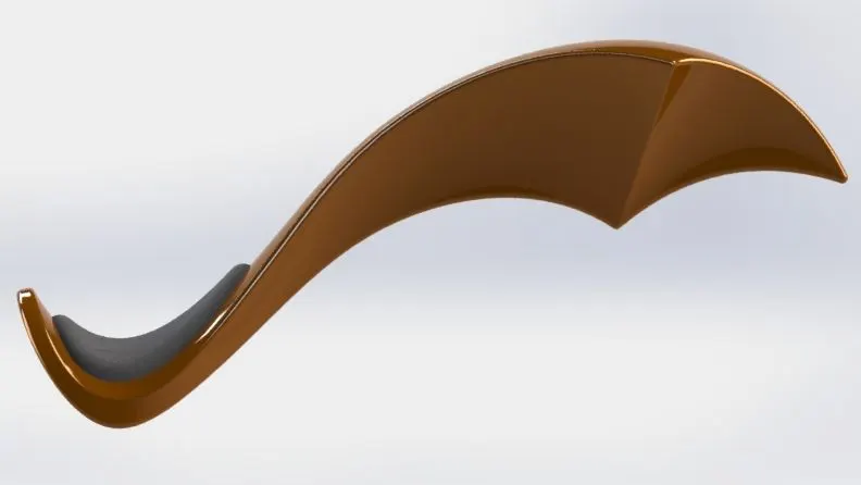
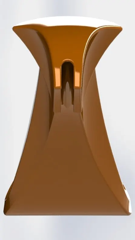
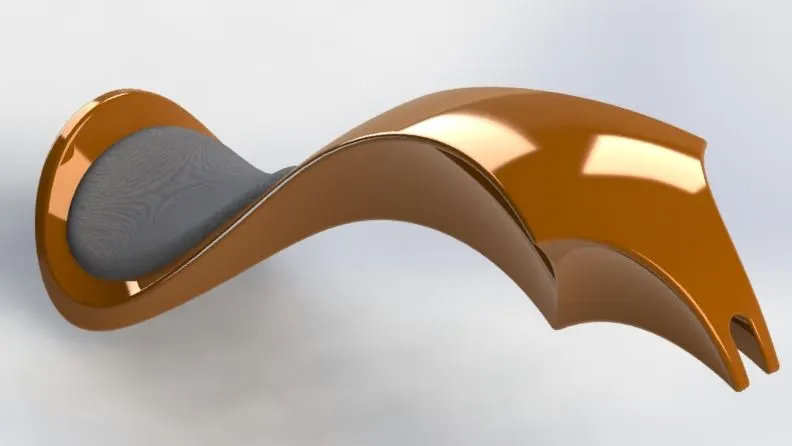
Figure 13 (images of the gas tank in front, side and isometric views respectively)
Top Face
- Underlay Fuel Tank was created using a blue print image of the chopper on the front plane.
- Sketch2 was created using splines on the front plane. It defines the front view path of the top face of the gas tank.
- The right plane and the end point of sketch2 were referenced to create Plane1.
- Sketch3 was created using a spline on the right plane. It defines the side view path of the top face of the gas tank.
- Sketches 2 and 3 were swept to create Surface-Sweep1.
- Sketch4 was created using a spline on the top plane. It defines the top view cross section of the top face scoops.
- Surface-Sweep1 was trimmed by Sketch4 to create Surface-Trim1.
Small Scoop
- The front plane and the first vertex from it on Surface trim1 were referenced to create Plane2.
- Sketch5 was created using a spline on the front plane. It defines the front view path of the lower edge of the forward scoop face.
- Sketch6 was created using a spline on the right plane. It defines the right view path of the edge between the two scoops.
- Sketch7 was created using a spline on the front plane. It defines the front view path of the edge between the two scoops.
- Sketches 6 and 7 were combined to create a composite curve called Curve1.
- The smaller scooped edge of the top face of the gas tank and Sketch5 were referenced with curve1 as a guide to create Surface-Loft1
Large Scoop
- The right plane and the vertex at the widest point of the top face were referenced to create Plane3.
- Sketch8 was created using a spline on the top plane. It defines the top view path of the lower edge of the large scoop.
- Sketch9 was created using a spline on the front plane. It defines the front view path of the lower edge of the large scoop
- Sketch8 and Sketch9 were combined to create a composite curve called Curve2.
- Sketch10 was created using line on the front plane. It defines a reference to the large scoop face.
- Sketch11 was created using line on the right plane. It defines a reference of the large scoop face.
- The large scoop edge on the top face, curve 2, Sketch10 and Sketch11 acted as references to create Boundary-Surface1
- All surfaces were mirrored about the front plane to create Mirror1.
- All surfaces were knitted to create Surface-Knit1
Seat
- Sketch12 was created using convert entities on the top plane. It defines the cross section of the seat.
- A the top face was line split by Sketch12 to create Split Line1
- The seat faces were blind surface extruded 25 mm to create Surface-Extrude1.
- The edge of the seat was symmetrically filleted by 20 mm to create Fillet1.
Bottom faces
- The lower edges on the small scoop faces acted as references to create Boundary-Surface2
- The lower edges of the large scoops and the lower edge of boundary surface2 acted as references to create Surface-Loft2.
- All surfaces were knitted to create Surface-Knit2
- The all edges were symmetrically filleted by 5 mm to create Fillets 2, 3, 4 and 5.
Chassis Cutout
- Sketch13 was created using splines on the front plane. It defines the front view cross section of the chassis cutout.
- Sketch14 was created using arcs and lines on the right plane. It defines the side view cross section of the chassis cutout.
- Sketch 13 and Sketch14 acted as references to create Cut-Sweep1
- The edges of the cutout were symmetrically filleted by 2 mm to create Fillet6.
- The gas tank net was shelled with a thickness of 3 mm to create Shell.
Appearance
- A painted car sienna appearance was applied to the gas tank.
- Decals were added to the top and all scooped faces for the final renders
Assembly Description
Figure 14 (images of the chassis in front, side and isometric views respectively)
For ease of assembly some of the planes were renamed to better reflect their positions. For clarity they have been referred to as they appear in the figures.
Chassis
- The chassis was positioned first.
- All other components are mated to the chassis either directly or indirectly through another component.
- When the chassis floats all components move with it.
Engine
- The engine front plane was made coincident to the chassis front plane to create Coincident1.
- The engine feet were made coincident to the chassis engine mount to create Coincident2.
- The side view face of an engine foot was offset from the side view face of the chassis engine mount a distance of 20 mm to create Distance1.
Stand
- One of the stand mounting pins was made concentric to a hole of the chassis stand mount to create Concentric1.
- The other stand mounting pin was made tangent to the other hole in the chassis stand mount to create Tangent1.
- The mounting pin side face of the stand plate was made coincident to the outside face of the chassis stand mount to create Coincident3.
Kickstand
- The top inside face of the kickstand cutout was made coincident to the top face of the chassis kickstand mount to create Coincident4.
- The cylindrical face of the kickstand mounting pin was made concentric to the face of the hole in the chassis kickstand mount to create Concentric2.
- The front plane was set at an angle limit of 0 to 75 degrees from the face of the chassis lower tube to create Limit angle1.
Transmission Belt
- An arced edge of the transmission belt was made concentric to a circular edge of the large engine transmission belt gear to create Concentric3.
- The two side faces of the transmission belt were set to the width of the engine transmission belt gear to create Width1.
- The top face of the transmission belt was set an angle of 7 degrees from the top face of the engine lower casing to create Angle1.
Oil tank
- The bottom face of the oil tank was made coincident to the top face of the engine upper casing to create Coincident5.
- The lowest edge of the bottom face of the oil tank was made coincident to the lowest edge of the top face of the engine upper casing to create Coincident6.
- The right plane of the oil tank was made coincident to the front plane of the chassis to create Coincident7.
Rear Wheel
- The rear wheel axle hole was made concentric to the chassis axle to create Concentric4.
- The rear wheel right plane was made coincident to the chassis front plane to create Coincident8.
- The rear wheel front plane was set parallel to the chassis right plane to create Parallel1.
Rear Fender
- The arced edge in the side view of the rear Fender was made concentric to a rounded face of the rear wheel to create Concentric5.
- The rear fender right plane was made coincident to the chassis front plane to create Coincident9.
- The rear fender front plane was set parallel to the chassis right plane to create Parallel2.
Chain
- Two inside faces of the inner links of the chain were set to the width of the rear wheel sprocket to create Width2.
- The large arc path of the chain was made concentric to an edge of the chassis rear wheel axle hub to create Concentric6.
- The top plane of the chain was set parallel to the top plane of the chassis to create Parallel3.
Gas Tank
- The right plane of the gas tank was offset from chassis plane2 a distance of 5 mm to create Distance2.
- The gas tank Bottom Plane Fuel Tank was made coincident to the chassis Bottom Plane Fuel Tank to create Coincident10.
- The gas tank front plane was made coincident to the chassis front plane to create Coincident11.
Front Forks
- The face of the front forks tri clamp connector tube was made concentric to chassis fork mount to create Concentric7.
- Two inside faces of the front forks tri clamps were set to the width of the chassis fork mount to create Width3.
- The front plane of the front forks was set a limit angle of 30 to -30 degrees from the chassis front plane to create Limit angle2.
- The front fork front plane was set parallel to the chassis front plane to create Posistion.
- Position was suppressed to allow freedom of movement to the front forks.
Front Wheel
- The face of the front wheel axle hole was made concentric to the front forks axle to create Concentric8.
- The front wheel right plane was made coincident to the front forks front plane to create Coincident12.
- The front wheel front plane was made coincident to the front fork Vertical Plane Front Fork to create Coincident13.
Front Fender
- The front fender front plane was made coincident to the front fork Vertical Plane Front Fork to create Coincident14.
- The front fender top plane was made coincident to the front wheel top plane to create Coincident15.
- The front fender right plane was made coincident to the front wheel right plane to create Coincident16.
Assembly Positioning
- The rear wheel tyre face was made tangent to the assembly top plane to create Tangent2.
- The face of the kickstand arm was made tangent to the assembly top plane to create Tangent4.
- The front wheel tyre face was made tangent to the assembly top plane to create Tangent4.
Renders
Decals
Decals were added to parts of the assembly. Close up images of these decal can be seen below
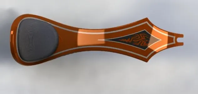
Figure 15 (image of the top face gas tank decal)
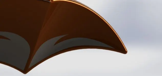
Figure 16 (image of the small scoop gas tank decal)
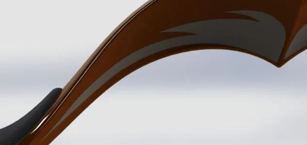
Figure 17 (image of the large scoop gas tank decal )
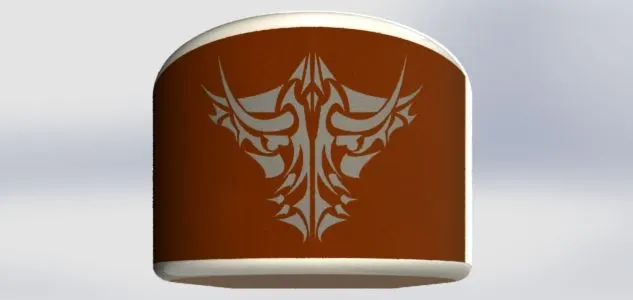
Figure 18 (image of the oil tank decal)
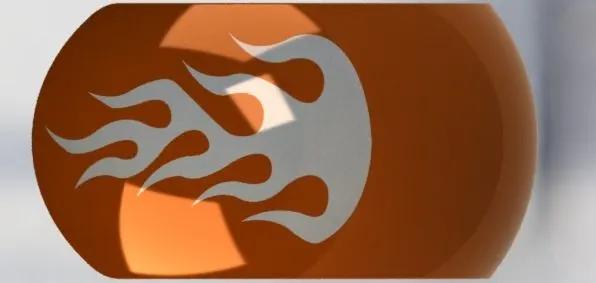
Figure 19 (image of the image of the rear fender decal)
Lighting
Default
Lighting was tweaked to best show off the bike. Courtyard reflections were added to reflective surfaces.
Colour Variants
A darker scene was used for these renders to add more contrast to the white colour variant and allow for a consistent background for the 4 display state render.
Set Camera
Camera 1 was added to the assembly. It views the bike from a flattering angle and brings in some perspective to the renders. From this angle very high quality and aesthetically pleasing renders have been produced
Final Renders
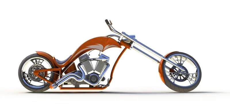
Figure 20 (image of the assembly in the front view)
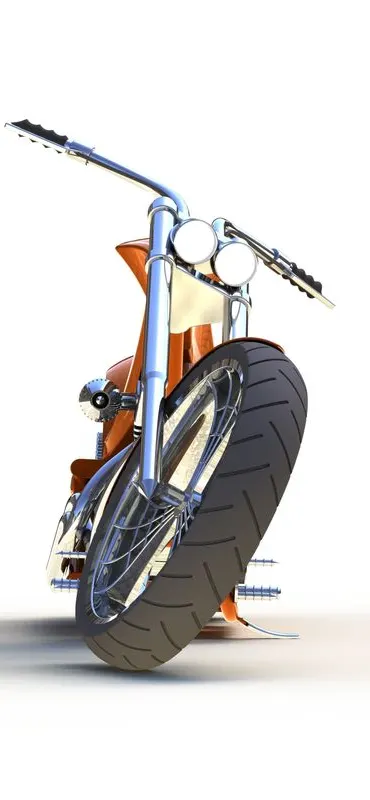
Figure 21 (image of the assembly in the side view)
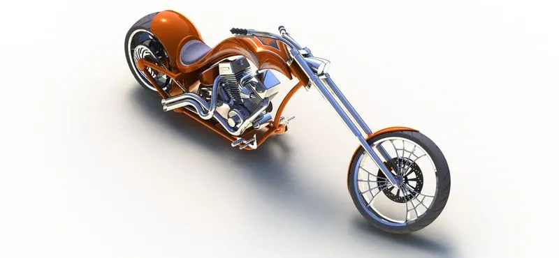
Figure 22 (image of the assembly in the isometric view)
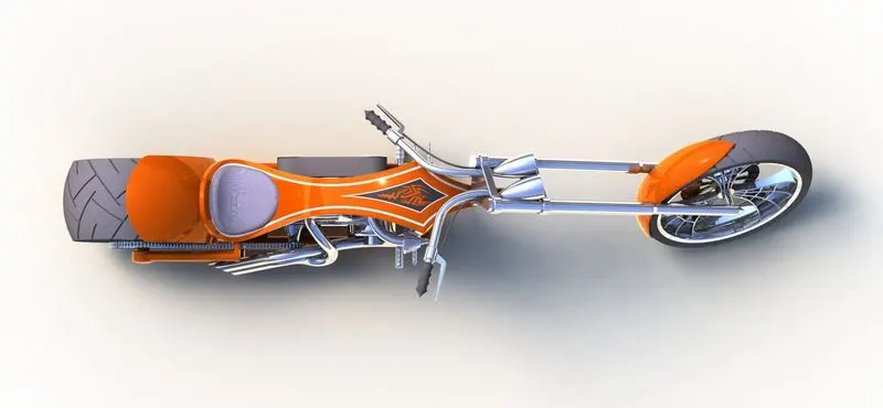
Figure 23 (image of the assembly in the top view)
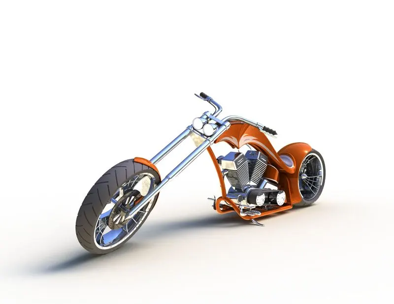
Figure 24 (image of the assembly from camera 1)
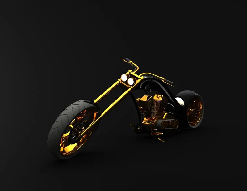
Figure 25 (image of the assembly in the black display state from camera 1)
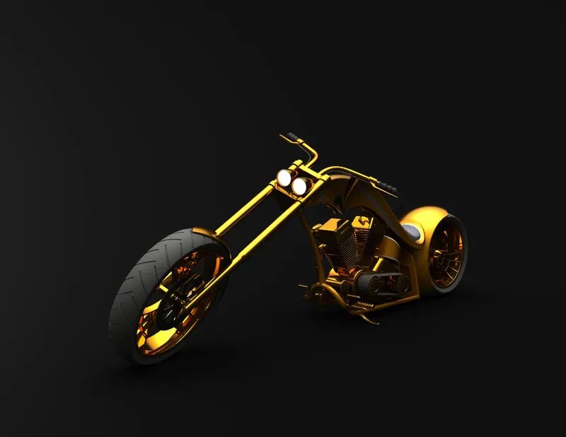
Figure 26 (image of the assembly in the gold display state from camera 1)
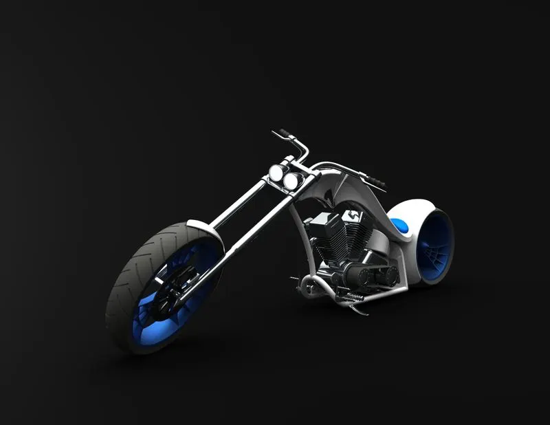
Figure 27 (image of the assembly in the white display state from camera 1)
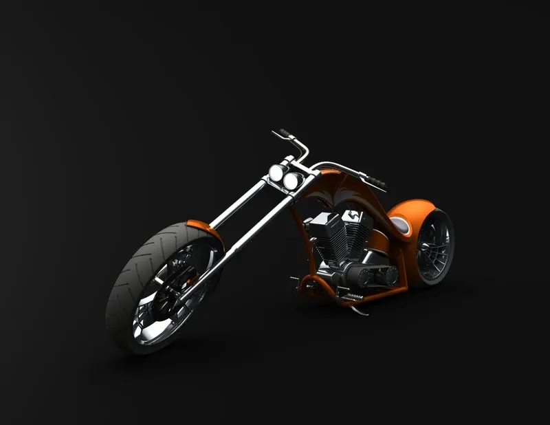
Figure 28 (image of the assembly in the siena display state from camera 1)
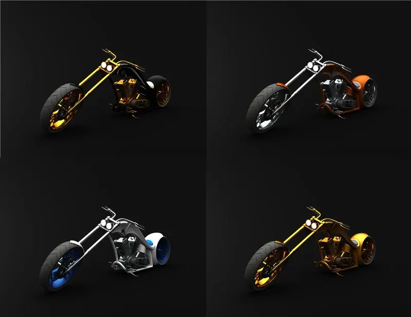
Figure 29 (image of the assembly in the four display states from camera 1)
Conclusion
Accurate Sizing
The models’ accurate size allows the designer to get sizing specifications for the parts. Accurate sizing also allows a designer to test the scale of parts against each other ensuring they all have a good fit and aesthetic.
Collision testing
Assembly of the model can result in part collisions. As in the case of the chain and the chassis and with the engine and the chassis. Knowing these parts collided prior to manufacturing allows the designer to update parts before prototyping begins, saving time and money.
Moving Parts
The moving handlebars and kickstand allow the designer to move these parts as they would move in real life. This allows the designer to adjust the turning circle of the bike and the flat spot on the kickstand.
More Parts
Certain parts in this model are very simplified, the engine particularly would benefit breaking into separate sub components. This would allow for a more detailed analysis.
More Moving Parts
Addition of a moving wheels, brake levers, sprocket, chain, transmission belt and transmission gears would enable the model to render the bike in motion.
Fittings
For the model to be used for design specifications it needs to include all of the screws, bolts and washers etc.. that would be required for assembly.
Aesthetics
The final renderings of the model are good with accurate positioning to the scene and the bike accurately stood. Several colour variants help to catch the imagination and enhance the models’ aesthetics..