Photo Realistic Rendering
Desigining, modelling, assembly and photo realistic rendering of an American Chopper.
Objective
To be ready for the role of mechanical design engineer or CAD engineer by creating a model of American chopper and rendering it in Soildworks and Solidworks visualize respectively.
Introduction
The amount of motorcycles available in the market is staggering. Motorcycles, Choppers, Bobbers, Crusier bikes, Touring, Street bikes come in different shapes, sizes and styles. Some are strictly utilitarian and serve a very functional purpose; however, some are strictly aesthetically pleasing and are just designed to catch people’s attention. For the uninitiated, all types can be a bit confusing and likely feel a bit unfriendly. However there are some prime differences that make every motorcycle type unique.
The standard type of motorcycle is a common favorite because it has a simple design and is suited for all purposes. Ergonomics are pretty neutral as it isn’t very forward leaning or rearward reclining. Seat height usually is in the shorter to middle range and can usually fit almost everyone comfortably. It is one of the most affordable forms of motorized transportation in the world. The motorcycle is typically mass produced in a factory.
As the name itself suggests, Chopper is is built from an original motorcycle which is chopped. A chopper motorcycle consists of a modified form of the original factory frame and only the most essential motorcycle parts to make it go at faster. Basically everything unnecessary to moving or stopping gets “chopped up” and some of the original parts are replaced with custom parts. The extreme style of this motorbike, which uses modified steering angles and lengthened forks, makes it an aesthetically pleasing sight. The design used in this project is inspired by American reality TV show named American Chopper, one of the most popular motorcycling shows, which featured some stunning custom manufactured choppers.
In general motorcycle or chopper consist of many parts. Designing individual parts requires taking into consideration general performance specifications and translate them in to technical specifications, simulation analysis, form design parameters such as physical appearance of a product, its shape, size, color, styling etc. However this project aims at creating a ' toy model ' of a chopper rather than working model, to get a fair insight about visualization of a final product.
Design Methodology
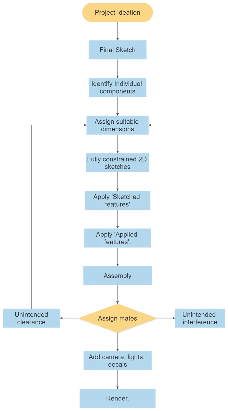
Project Ideation
Ideation is the process where ideas are generated through brainstroming, sketching using pen and paper or software like Adobe Photoshop/ Autodesk sketchbook. The aim is to generate a large quantity of ideas that can then be filterd and cut down into the best, most practical ones. A good sketch conveys the designer’s ideas without being overly worked. Drawings don’t have to be crisp and sharp. The main focus at this point is to convey imagination and fresh thinking. Generally ideation and sketching is done by industrial designer and not much by design or CAD engineer but ideation and sketching skills are plus points for anyone trying to convey his/her ideas efficiently.
Fully constrainted 2D sketches
A sketch is almost always the first step in designing a new part. Well-developed sketches are one of the major keys to creating intelligent and flexible models. The sketch is fully defined in Solidworks if the lines on the sketch are all black. This means that there can be no unexpected changes within the model due to all the geometry of the sketch being fully defined. Having a sketch be fully defined is not only important for displaying all the key geometry of the sketch, but it allows for easier changes. This is to prevent errors in the final product and absolutely make sure all the dimensions are correct. If sketches are not fully constrained, it is almost too easy to accidentally miss a dimension or change it accidently.
3D Modelling
After creating fully constrined sketches, the next step is to convert them into 3D geometry using numerous modelling commands in Solidworks. It is worth noting that there are two categories of features in Solidworks – sketched features and applied features. Sketched features require the use of a sketch in order to be created, and include features such as Extruded Boss/Cut, Revolved Boss/Cut and many others. Applied features do not require a sketch, and are applied directly to existing geometry. Shell and fillet features fall into this category.
Some of most widely used commands in this project are as follows
Extruded boss - Extrudes a sketch along a straight line path to add material. As a sketched feature, it requires a sketch before use. It allows to take a 2D sketch and add thickness to it in the third dimension.
Extruded cut - Helps to remove the material by projecting sketched section normal to sketching plane. It is similar to extruded boss feature but removes the material.
Revolved boss - Tool which is used to create solid 3D model around an axis. Sketch can be revolved around an axis to add materials to it.
Revolve cut - It remove material by revolving one or more profiles around a centreline.
Swept boss - Hepls to create a feature that follows a complicated or irregular path. There are two main requirements to create a swept Boss - A closed profile and a path.
Project curve - It creates a 3D sketch using two 2D curves in two different planes.
Pattern feature - This tool helps to create multiple ipatterns of same feature along a planar or 3D curve. A pattern can be a linear/ along irregular path based on open path or circular based on closed circular profile.
Shell - The command allows to define a wall thickness and automatically hollow the part, while allowing faces to be removed as needed.
Fillet - Fillets serve to round off edges and/or corners by adding or removing material, depending on whether the edge is internal or external.
Mirror - Creates a copy of feature/multiple features mirrored about face or a plane.
Dome - Allows users to apply domes to planar surface or irregularly shaped contours.
Combine - Several bodies can be added togther or coomon intersection part of a multi-boby can be subtracted and kept as a single body
Extruded surface - Like extruded boss, it extrudes a profile/sketch in 3D space into zero thickness surface.
Lofted surface - Generates by multiple 3D Curves or existing edges creating a smooth tangency between the selected curves. Match Points can be selected to specify the orientation and path of the loft. sometimes guide curves can be added to dictate the shape of the loft.
Surface trim - It uses any surface plane, or sketch as a trim tool to trim intersecting surfaces.
Knit surface - It allows to combine two or more surfaces into one.
Individual parts
Most of the parts of the chopper are generated using solid modelling and surface modelling is used infrequently. Following are the parts modelled and rendered in Solidworks.
1. Transmission Belt
This belt connects two pulleys which are on one side of engine block and snugly fits on the grooves of the pulleys. The belt is made of a rubber-like, but mostly a very strong synthetic material which lasts a very long time.
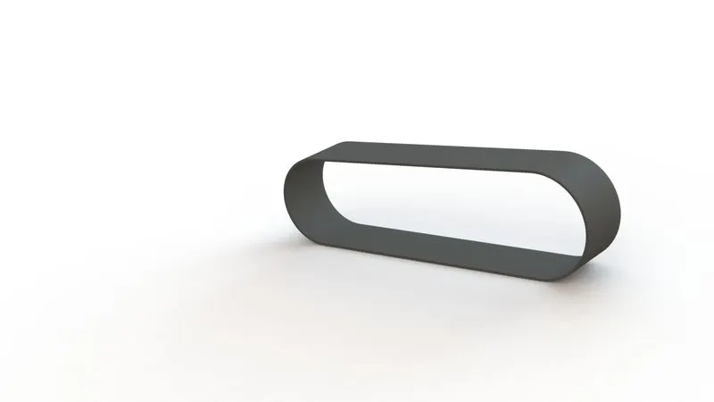
Commands used -
- Extruded boss
- Fillet
Appearance - Matte rubber
2. Oil Tank
This oil tank is placed above the engine block and below gas tank. Since it is meant for storage of fuel, it is made hollow with the help of Shell command.
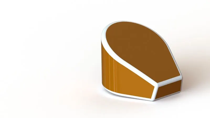
Commands used
- Extruded boss
- Combine
- Fillet
- Shell
Appearance - Chromium plate and Siena
3. Kickstand
A side stand is a single leg that simply flips out to one side usually the left side. It is made flat at lower end for its proper resting on the ground. Upper end of kickstand is fixed to the Chassis.
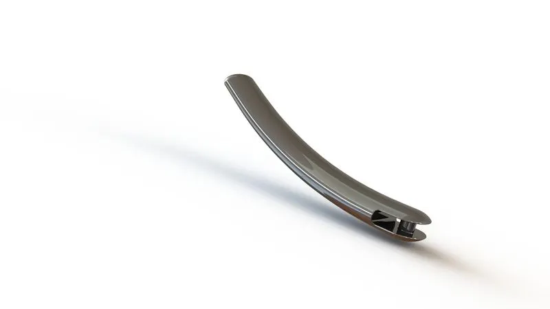
Commands used
- Extruded boss
- Extruded cut
- Lofted boss
- Dome
- Split
- Fillet
Appearance - Chromium plate
4. Pedal
This is a simple type of pedal which is meant for shifting gears or applying brakes. Pedals are fixed to both sides of chassis. However only one pedal (right sided) is sketched and designed. Other pedal is made in assembly environment by 'mirror components' command.
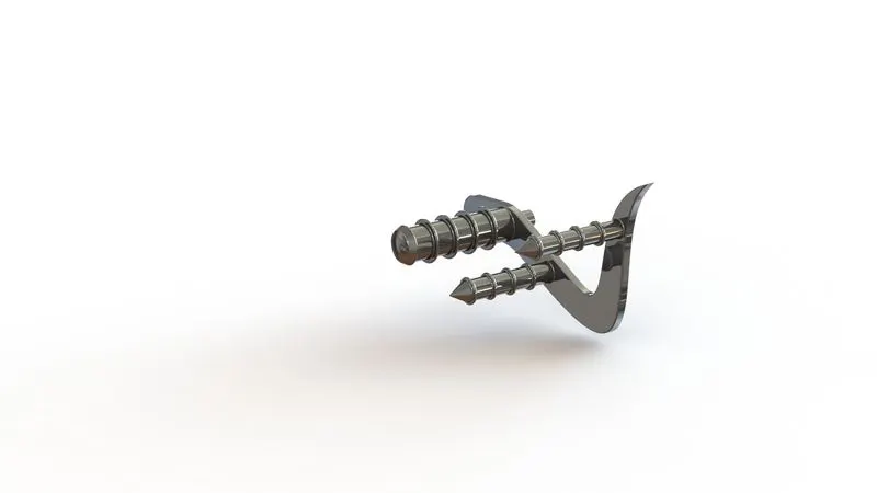
Commands used
- Extruded boss
- Revolved boss
- Dome
- Fillet
- Chamfer
- Linear pattern
Appearance - Chromium plate
5. Chain
The prime function of the chain is to transmit the power from gearbox to the sprocket attached to rear wheel. It is one of the most complex parts of this project and consists of total 390 solid bodies (130 soild bodies of pins and 260 solid bodies of chain links). Since chain links are required to orient along the contours of the chain in frquent manner, two blocks of chain links are created and saved in '.SLDBLK'. Saving them in block format enables them to be imported and reoriented as per requirements.
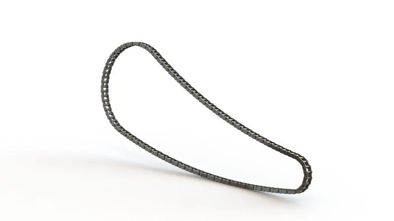
Commands used
- Extruded boss
- Fillet
- Circular pattern
- Mirror
Appearance - Chromium plate
6. Front and Rear Fenders
Fenders frame the wheels and its primary function is prevent sand, mud, rocks, liquids, and other road spray from being thrown into the air by the rotating tire. Fenders also protect motorcycle from getting splattered in grime from the road, especially on wet rides. The front fender of the chopper is made pointed at one end by cutting away some material using split command. Rear fender is thicker and shorter compared to front fender and is rounded at both ends.
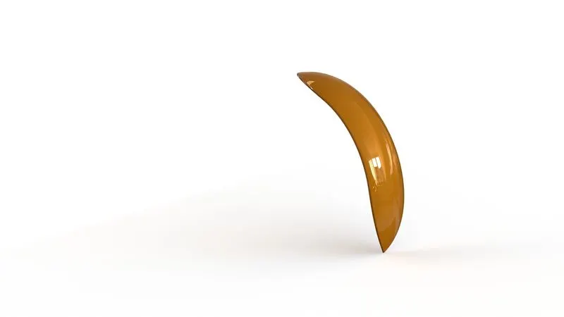
Front Fender
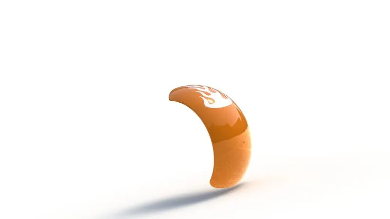
Rear Fender
Commands used
- Revolved boss
- Split
- Fillet
Appearance - Chromium plate and Siena
7. Front and Rear Wheels
The front wheel is designed to be multi-body part which consists of rim, rotor, caliper and tyre. The rear wheel is also designed to be multi-body part and additionally has sprocket along with rim, rotor, caliper and tyre. Rear wheel is thicker than front wheel. Circular pattern command is used to distribute tyre marks all along the body of tyre.
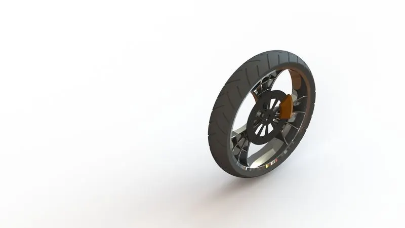
Front Wheel
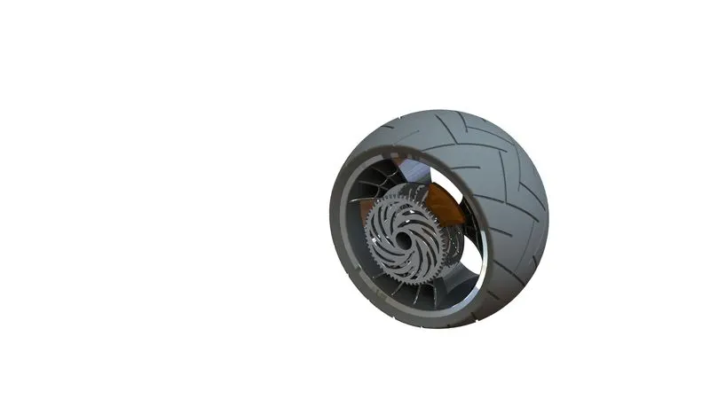
Rear Wheel
Commands used
- Revolved boss
- Extruded boss
- Extruded cut
- Combine
- Circular pattern
- Fillet
- Chamfer
Appearance - Chromium plate for rim, rotor, sprocket. Matte rubber for tyre. Siena for caliper.
8. Chassis
Chassis is the skeleton or core structure of the motorcycle. All other components of chopper like engine block, pedal, kickstand, gas tank, front fork, rear wheel are attached to the chassis.
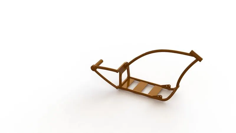
Commands used
- Project curve
- Swept boss
- Extruded boss
- Extruded cut
- Mirror
- Dome
- Combine
- Split
- Chamfer
- Fillet.
Appearance - Chromium plate and Siena
9. Front Fork
Lenghtened fork, roughly angled at 45 degrees for a stretched-out appearance is a unique feature of any chopper. The front fork is designed to be a multi-body part which consists of frame of fork, handlebar, brake levers and headlights. Since handlebars and headlights are symmetrical, only half of it is designed and mirrored along mid plane.
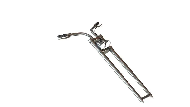
Commands used
- Extruded boss
- Extruded cut
- Revolved boss
- Revolved Cut
- Combine
- Mirror
- Dome
- Linear pattern
- Fillet
Appearance - Chromium plate
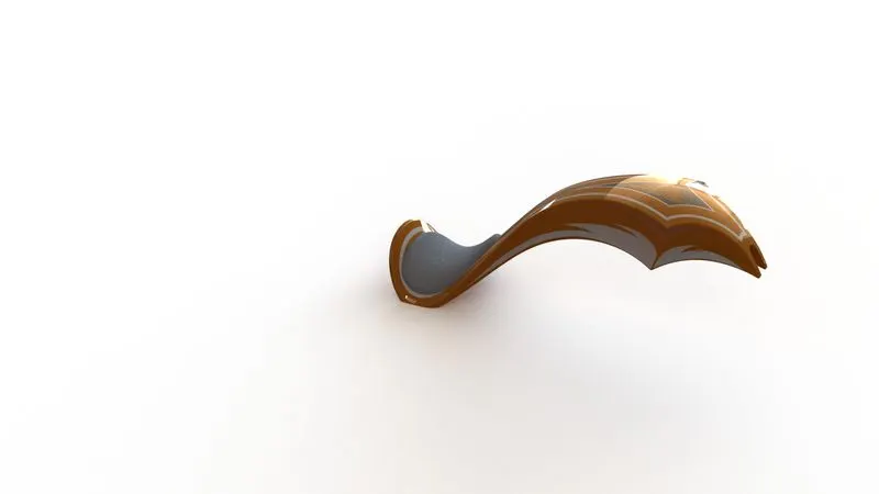
10. Gas Tank
Gas tank or fuel tank is designed mostly using surfacing commands. It is designed according to ideation sketch. A rough blueprint of ideation sketch can be imported in Solidworks and can be used as a reference for drawing irregular contours of an object. A point to note here is that the blueprint is only a source of reference and it's not always wise to match 2D sketches or 3D models meticulously with its counterparts in blueprint. A slight tweak or twitch with respect to blueprint can always be incorporated in 2D sketches.
Commands used
- Project curve
- Swept surface
- Lofted surface
- Boundary surface
- Swept cut
- Mirror
- Shell
- Fillet
Appearance - Chromium plate and siena for tank. Fabric cloth for seat.
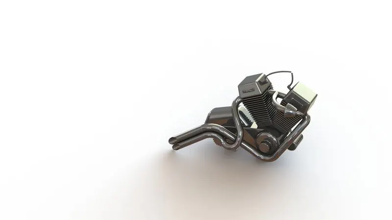
11. Engine
The engine for the chopper is V engine and designed to be a multi-body part. It consists of cylinder, cooling fins, engine body, exhaust manifolds, spark plug representation, pulleys for transmission unit. While designing exhaust manifolds, a unique command named 'composite curve' is employed. Composite curve converts two different entities drawn on two different planes into a single entity which can further be used for other operation like sweep or extrude.
Commands used
- Project curve
- Composite curve
- Extruded boss
- Extruded cut
- Linear and circular pattern
- Mirror
- Dome
- Revolved boss
- Swept boss
- Fillet
- Chamfer
Appearance - Chromium plate.
Assembly
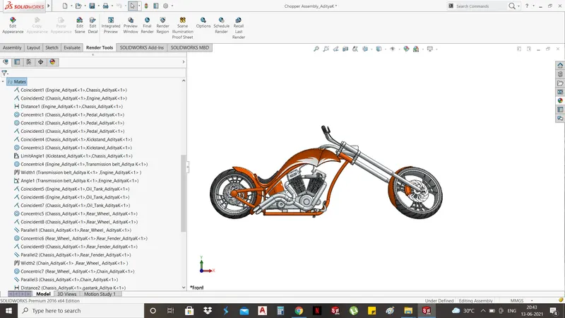
After modelling individual components, next step is to create an assembly with the helps of standard and advanced mates between components.
While creating an assembly it is important to identify that one single component which can act a 'central component' or reference for establishing mates with other components. This is required for free floating of complete assembly in assembly environment. In case of Chopper, chassis is considered as that central component/central reference with which other newly added components in assembly environment are referenced back to. A coincident mate is applied between front plane of assembly environment and mid plane of chassis. All other components are mated with respect to front, side or top plane of chassis and not with planes in assembly environment. Such kind of mates make sure whole assembly, comprised of individual components, moves/floats freely when chassis is moved.
It is important to make sure that chopper should appear to be rested properly on the ground. A tangency mate is applied between tyre surface and top plane of assembly environment. Such mate ensures that while rendering, chopper appears to be rested on the ground of the background scene and not appears to be randomly floating in 3D environment.
While creating assembly some standards mates such as coincidence mate, concentric mate, tangency mate and parallel mate are widely used. Advanced mates are also incorporated in assembly. For insstance angle mate is used to limit angle of rotation of front fork and kickstand, width mate is used for belt and pulleys for giving a realistic look.
Rendering
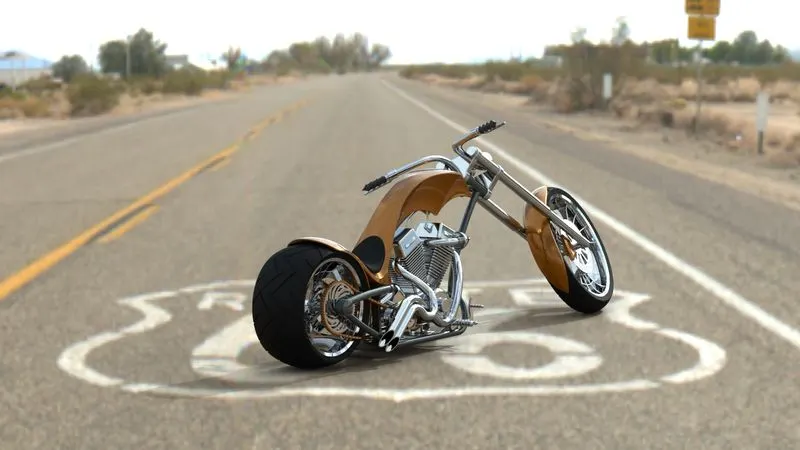
As asthetics and apperance are equally important for any product, it is always advisable to devote some time for rendering. Rendering generates a photorealistic image of the object. Its all about creating a graphically perceivable depiction of the object. Rendering makes a product presentable for potential customers. It eliminates the need to physically transport the real-life model to the client or asking the client to visit your office. The rendered image incorporates the appearances, lighting, scene, and decals included with the model. It can also simulate real-life effects from ambient lights to shadows and reflections.
Solidworks has 'Photoview 360' , 'Solidworks Visualize' as rendering tools. PhotoView 360 is a one of the add-ins of the Solidworks. PhotoView 360 enables users to create sophisticated, high-quality renderings of their design directly within Solidworks. It gives users the ability to demonstrate and interact with CAD models in 3D, providing perspectives and angels that would be unavailble in 2D. Solidworks Visualize is a standalone software package designed to take 3D CAD data and transform it into photorealistic images and animations. It enables users to develop rich, lifelike visual content with ease. It is worth noting here that Visualize is not a replacement for PhotoView 360. Visualize is appropriate when there are minor or very few anticipated design changes. If there are many design changes in the pipeline, it's more efficient to use PhotoView 360 as it's built right within Solidworks. PhotoView 360 is best used when output quality isn't a top priority. For this project, both Photoview 360 and Solidworks visualize have been employed for rendering.
Addings Decals, Cameras and Lights
Decals, which are commomly known as 'stickers',can be attached to individual components to enhance their apperance. Solidworks has plenty of option which deals with illumination of decals, orientation of decals. It has 'projection option' which helps to apply decals, without distorting it, on cylindrical and spherical surfaces. In this project, decals are applied on the gas tank, oil tank and rear fenders.
Solidworks provides an option of customizing own camera according to rendering needs. If we want certain area of a component to be more highlighted, a camera can be added accordingly. Camera postion and rotation can be set as per needs. For precise rendering requirnments, Solidworks has options such as 'Field of view' which deals with view angle, customized aspect ratio, dimensions of view rectangle and 'Depth of field' option which gives a liberty to select a part of component where highest quality of render would be obtained. In this project, a single camera is added as per rendering requiremnets. It is worth noting here that 'perspective mode' should be always be on while rendering, irrespective of presence of customized camera.
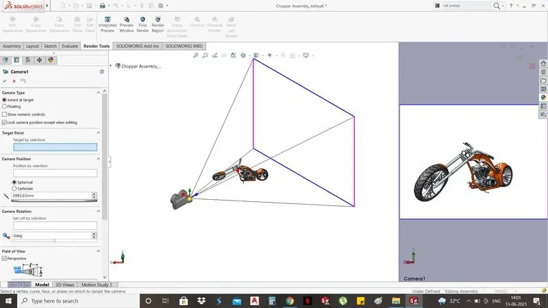
Camera setup
Solidworks has inbulit lights but it gives a liberty to set up lights as per rendering needs. It gives options of adding spot lights, dirctional lights, point lights and sun light for a background scenes. No cutomized lights are added in this project for rendering.
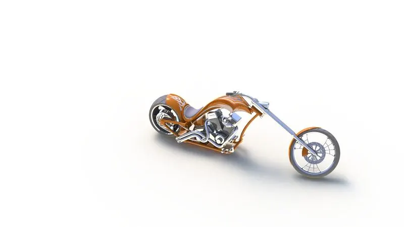
Rendering using Photoview 360
Camera view
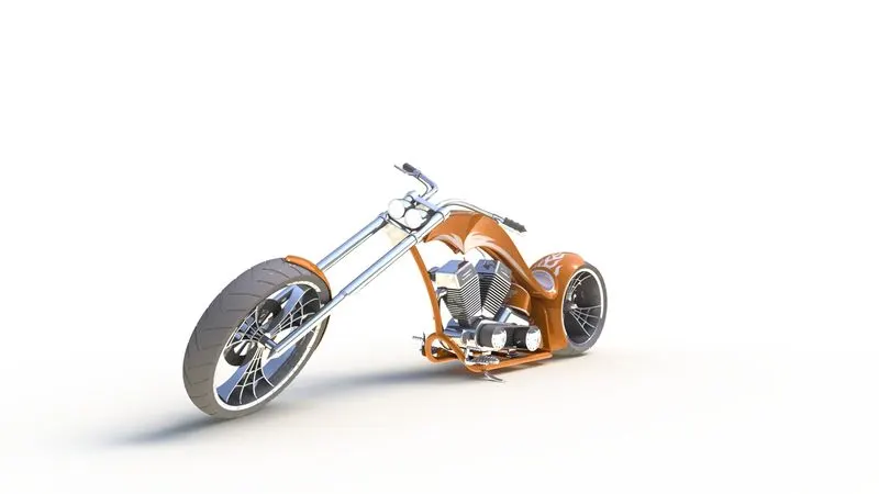
Front View
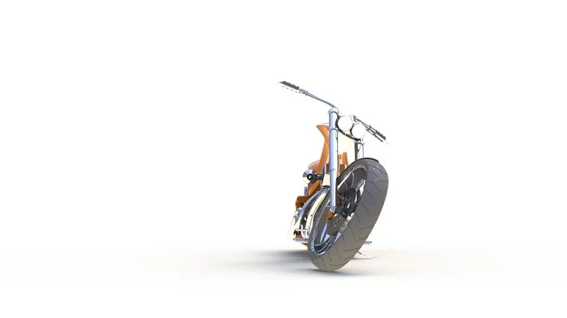
Left side view
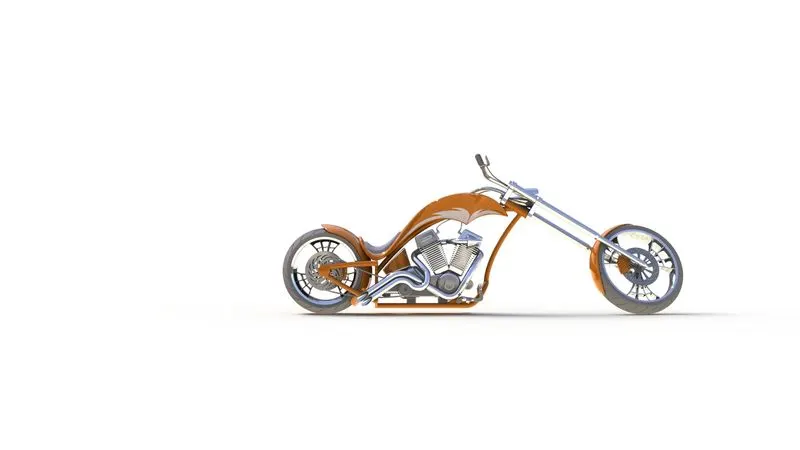
Right Side view
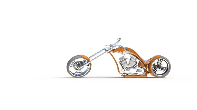
Isometric view
Rendering using Solidworks Visualize
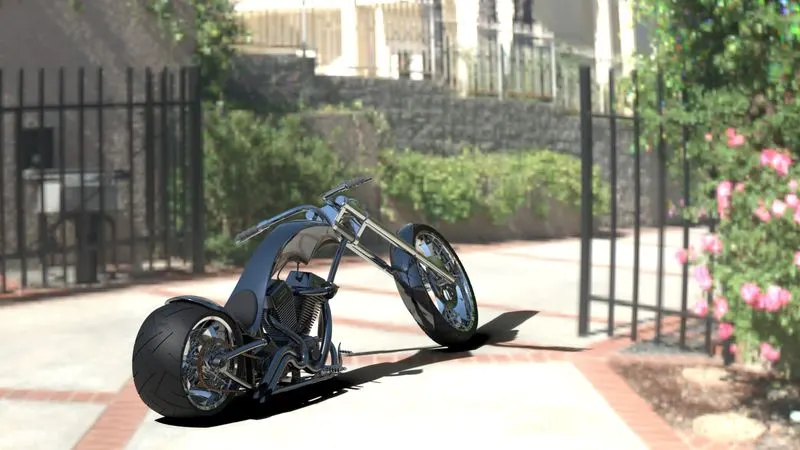
Additional rendering with different appearance
Conclusion
Working on this project was a very good experience. I had opportunity to learn an efficient way of creating fully constrained sketches. This project has really enhanced my skills in solid modelling and assembly. It has helped me to realize that there is not a single way but multiple ways to model a single object. It is mainly upto designer how he/she wishes to model a part. This project not only introdued me to some mundane features (like extruded, revolved boss) and some unique features like (composite, project curve, combine) but crux of every command (like applying 'end conditions', feature scope, deviating the source of sketch) which is truly time saving. Most importantly, this project has helped me to understand the rendering process which is generally outsourced to the third party once design is finalised. All in all the project was a valuable learning experience