Photo Realistic Rendering
MODELLING OF AMERICAN CHOPPER USING SOLIDWORKS
INTRODUCTION:
SolidWorks is computer-aided design software owned by Dassault System. It uses the principle of parametric design and generates three kinds of interconnected files: the part, the assembly, and the drawing. Therefore, any modification to one of these three files will be reflected in the other two.
Objective:
The main objectives of this project are:
- To create parts of American Chopper.
- To assemble the parts created.
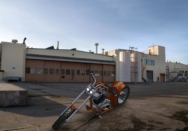
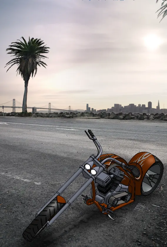
- To create photorealistic model using photoview 360.
Design Approach:
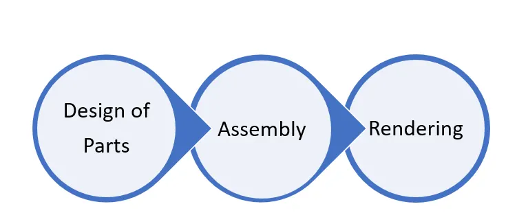
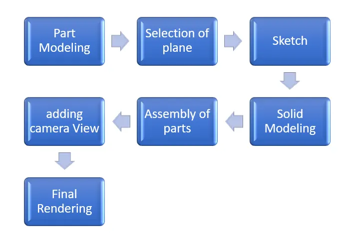
Parts Modelled:
- Kickstand
- Transmission Belt
- Engine
- Fenders
- Chassis
- Wheels
- Front Fork
- Oil Tank
- Gas Tank
- Chain
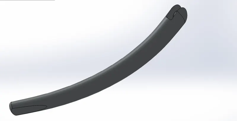
Kickstand:
Kickstand is also known as side stand. It is used to rest the chopper on the ground.
Tools used to create model:
- Sketch:
Sketch is a 2-dimensional representation of a model.
In these different types of entities are used like circle, line, rectangle, spline, etc.
- Loft:
Loft is used to generate complex geometry. It is done by interpolating surfaces between various cross-sections of the model.
- Dome:
This tool is used to create a dome like shape on a face. - Extrude Boss:
This tool is used to convert a 2-d model in to a 3-d model.
- Extrude Cut:
This feature is used to remove the material from a 3-d model. It is quite opposite to extrude boss.
- Fillet:
Fillet used to create curved surface on the edges of a part model.
Transmission Belt:
Transmission belt is used to transmit the power from engine to gear box.
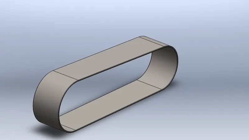
Features used to create this model are:
- Sketch
- Extrude
- Fillet
- Offset:
You can offset sketch entities such as spline, arc, sets of edges by a specified distance.
Engine:
Engine is the heart of a bike. It is used to convert chemical energy into heat energy and heat energy into mechanical energy.
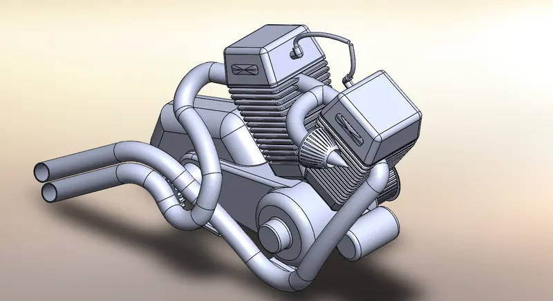
Features used in modelling the engine are:
- Composite curve:
This tool is used to unite 2 curves to a single one.
- Projected Curve:
This tool is used to project the curve from one surface to another. - Sweep:
We can create a shape by moving a 2-d sketch profile along a 2D or 3D sketch.
- Extrude cut
- Boss Extrude
- Mirror
- Circular Pattern
- Fillet
- Dome
- Offset
Chassis:
Chassis is also known as skeleton of a bike. It forms the basic frame on which components like fuel tank, wheels, gas tank, forks are attached.
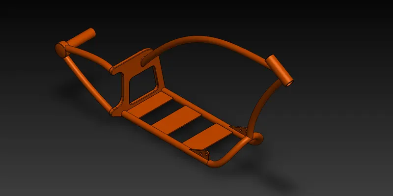
Features used in this are:
- Sketch
- Convert Entities:
It allows users to make a copied projection of a given sketch, face, or set of edges onto the active sketch plane.
- Project Curve
- Split
- Sweep
- Trim
- Revolve
- Extrude Cut
- Fillet
- Combine
- Offset
Fenders:
There are 2 fenders present in an American chopper they are front fender and rear fender.
Front Fender:
It is provided on the front fork above the wheel to protect the rider and the chopper from foreign particles.
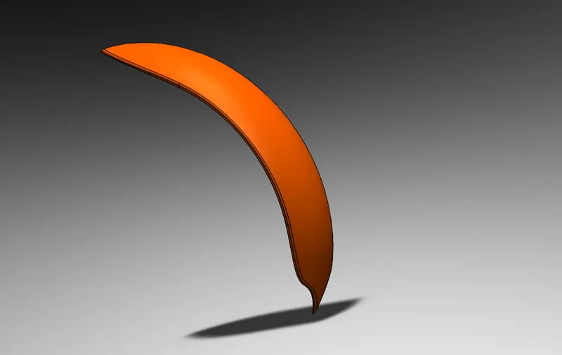
Features used to model this are:
- Sketch
- Offset entities
- Trim Entities:
Trim Entities are mainly used for removing unwanted parts or portion from the design.
- Revolve
- Split
Rear Fender:
Rear fender application is same as that of front fender. It is mounted above the rear wheel.
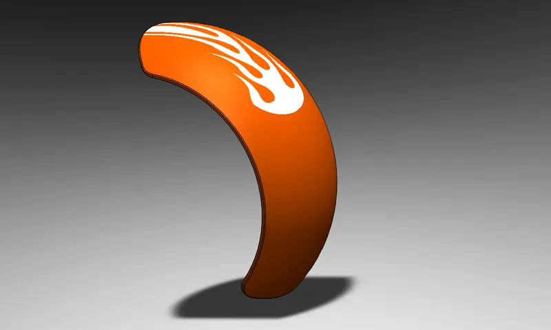
Features used to model this part are:
- Sketch
- Offset Entities
- Trim Entities
- Revolve
- Appearances
Wheels:
There are 2 wheels, one is front wheel and another is rear wheel.
Front wheel:
A wheel is a circular block made up of steel/alloy material. It is covered with tyre which is made up of rubber and thin wires.
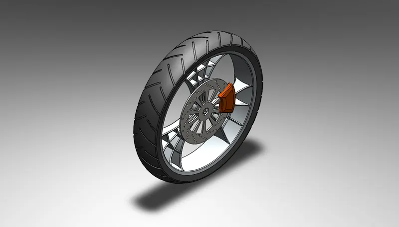
Features used:
- Sketch
- Revolve
- Trim
- Fillet
- Boss Extrude
- Revolve Cut
- Circular Pattern:
It is used to create spokes and grooves in a circular way on wheel and also used to create holes on disc of front wheel.
- Chamfer
- Cut Extrude
Rear Wheel:
The disc and sprocket are attached to rear wheel. The chain is connected between engine and rear wheel.
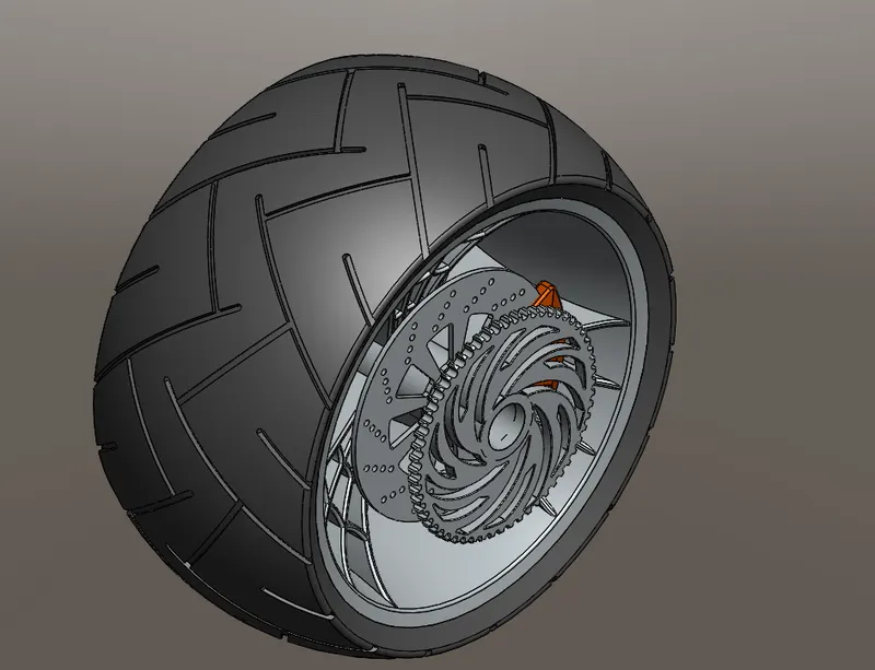
Features used:
- Sketch
- Revolve
- Trim
- Circular pattern
- Fillet
- Extrude Boss
- Linear Pattern
- Chamfer
- Extrude Cut
Front Fork:
Forks are the hydraulic shock absorbers with internal coil springs. They allow the front wheel to react to imperfections on road.
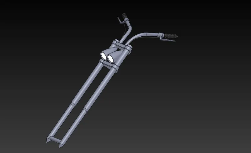
Tools used:
- Sketch
- Extrude
- Trim
- Sweep
- Revolve
- Split
- Mirror
- Combine
- Project curve
- Sweep
- Move/Copy bodies:
This feature is used to move or copy a body from one place to another.
Oil Tank:
Oil tank is used to store the oil requires to run the engine.
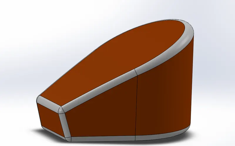
Tools used:
- Sketch
- Boss Extrude
- Combine:
Combine is used to combine two bodies by adding or subtracting. - Fillet
- Shell:
It is used to define the thickness of thin and thick shell elements.
Gas Tank:
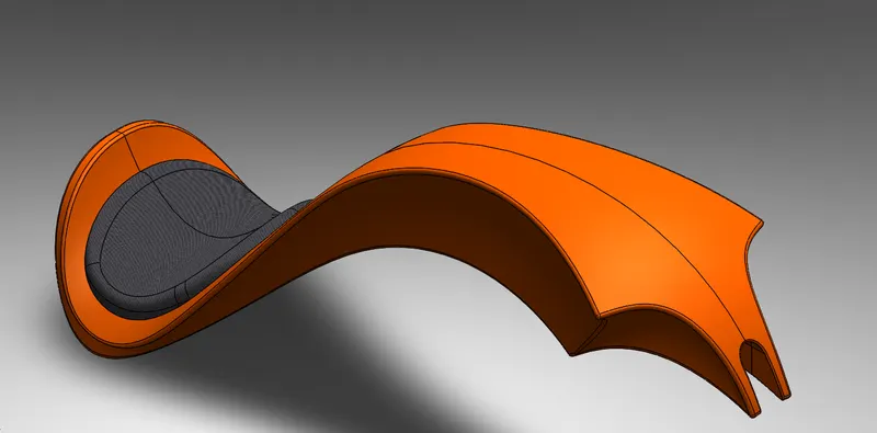
Tools used:
- Trim
- Projected Curve
- Sweep
- Loft Surface
- Surface Trim
- Surface Knit:
It is used to knit the two edges of the surface together and also it reduces the gap between two edges.
- Sweep Cut
- Fillet
Pedal:
Pedal is attached to chassis. It is used to place the leg of rider for comfort.
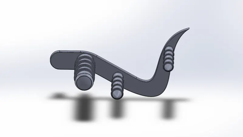
Tools used:
- Sketch
- Extrude
- Fillet
- Chamfer
- Linear pattern
- Dome
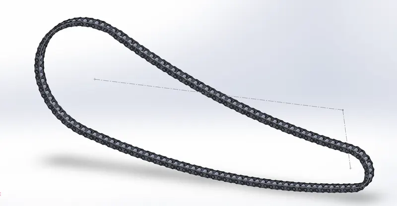
Chain:
Assembly of Chopper:
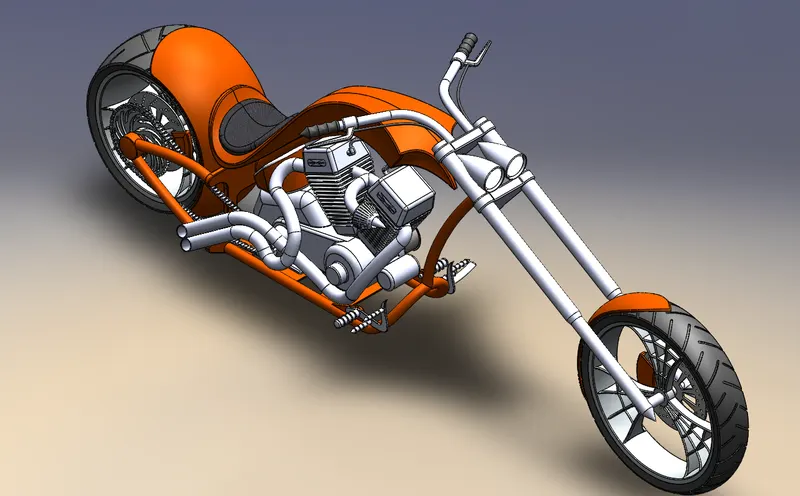
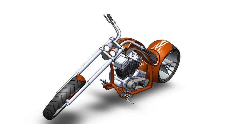
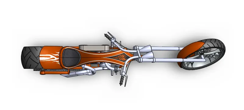
In this the parts modelled are assembled into one.
Initially chassis part is made fix and remaining parts are added one by one to form an American chopper.
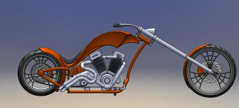
Rendering:
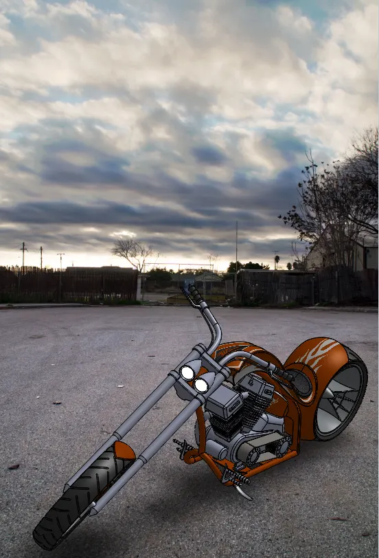
Rendering is the process of creating realistic images of the model.
In this rendering is done using “Photo-View 360”.
Conclusion:
- The parts of the American Chopper are modelled.
- The parts are assembled to form an American chopper.
- Realistic images of American Chopper are obtained with the help of Photo-View 360.