Photo Realistic Rendering
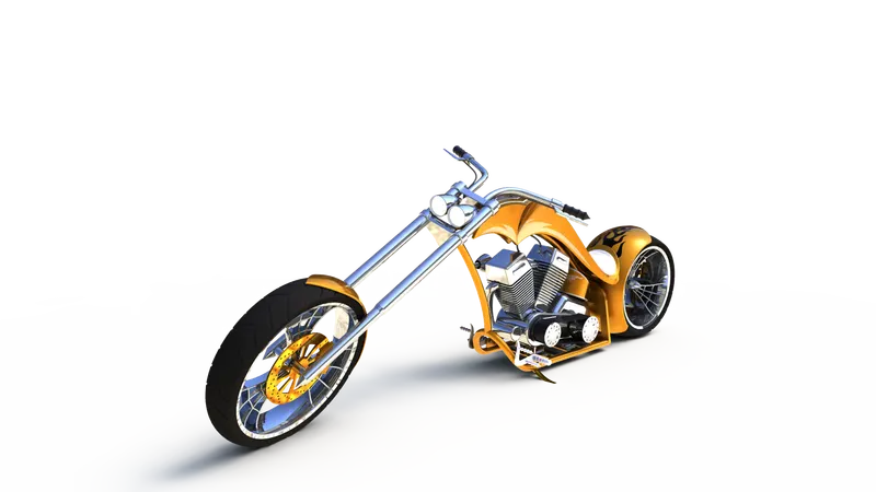
TITLE: - DESIGNING OF AMERICAN CHOPPER WITH PHOTO REALISTIC RENDERING USING SOLIDWORKS
OBJECTIVE:
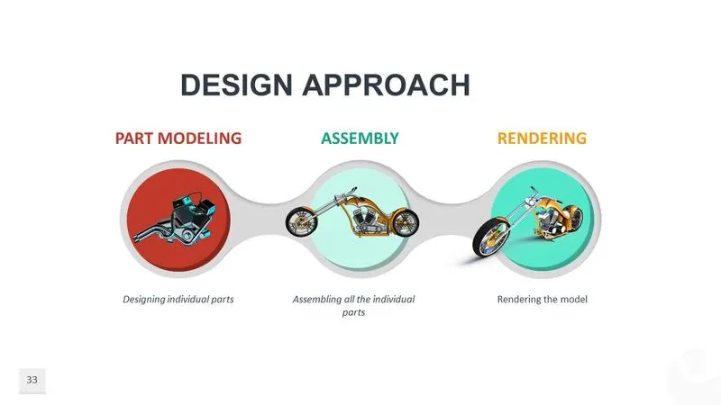
- To design individual parts of the chopper
- To assemble all the individual parts of the chopper model
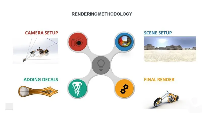
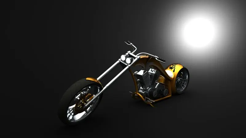
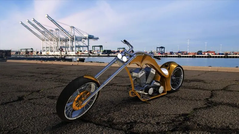
- To render the chopper model by adding appearances, decals, lights, cameras, and background scene
INTRODUCTION:
American chopper bikes are motor bicycles built by Orange county choppers for a specific corporate or celebrity customer. These bikes are motorcycles in which the theme of the motorcycle takes priority over everything else, influencing the frame dimensions, paint scheme, and overall 'feel of the motorcycle. The function of a motorcycle usually takes a backseat to the presentation of the theme, and these motorcycles attract attention solely on the premise of the theme itself. Customer bikes are built for and generally to the specifications of a particular customer. Although the customers typically give OCC creative freedom to do what they will, some clients have a specific idea in mind and expect OCC to reproduce their mental picture literally.
SOFTWARE USED:
- SOLIDWORKS 2017
- PHOTOVIEW 360
PART MODELLING
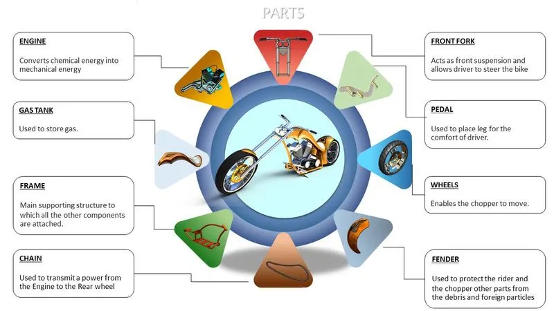
FEATURES USED WHILE MODELLING:
- SKETCH: Sketch is a 2D representation of the model. Some of the sketch commands are
- Line- In sketch line is created by choosing different types like centerline, midpoint line, and construction line
- Arc- It is a three-pointed arc that can be created on basis of positioning points.
- Smart Dimensions- The dimensions of any sketches can be changed easily in required situations by using this command.
- Sketch picture - This command is useful in inserting required pictures for the modeling part.
- Offset- It Offsets one or more sketch entities or selected model edges
- Mirror- It used to create a duplicate curve about the required curve or plane
- Spline- It is used to create irregular curves
- Trim – it is used to trimming curves.
- Extend - It can extend the entities to nearby geometry
- EXTRUDE BOSS/BASE- It is used to create 3d objects from reference sketches.
- REVOLVE BOSS/BASE- It is used to create a solid feature by revolving a sketch about an axis
- SWEEP- It is a tool in which a 2D cross-section is moved along a pre-set path to creating a 3D object.
- LOFT- Loft is almost the same as sweep, but it requires more than 1 cross-section
- PROJECT CURVE- It is a tool used to form 3D curves from two 2D curves from two different planes
- EXTRUDE CUT- it is used to remove material from a 3d object by using a reference sketch.
- REVOLVE CUT- It is used to cut a solid feature by revolving a sketch about an axis.
- FILLET- It creates a rounded internal or external face on the part
- CHAMFER- It creates a straight line which bevels the edges of objects
- DRAFT- Draft tapers faces using a specified angle by selecting faces in the model
- DOME- It creates a dome to the selected planar and non-planar faces
- SHELL- The shell tool hollows out a part, leaves open the faces that are selected.
- LINEAR PATTERN- It is used to create multiple instances of one or more features along one or two linear paths
- CIRCULAR PATTERN- It is used to create multiple instances of one or more features about an axis
- SWEEP SURFACE- It is a tool in which a 2D cross-section is moved along a pre-set path to creating a surface
- KNIT SURFACE- The Knit Surface tool is used to combine two or more surface
- TRIM SURFACE- It is used to trim surfaces by using curves, sketches, or surface as a trim tool
TRANSMISSION BELT
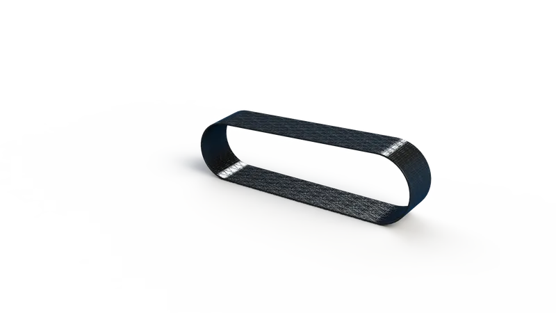
Features used:
- Sketch
- Extrude boss/base
- Fillet
- Appearance
KICKSTAND
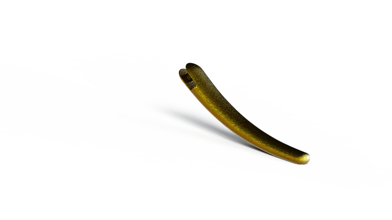
Features used:
- Sketch
- Loft
- Dome
- Extrude cut
- Fillet
- Appearance
PEDAL
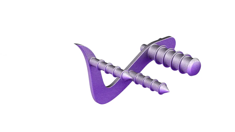
Features used:
- Sketch
- Loft
- Dome
- Extrude cut
- Fillet
- Appearance
CHAIN
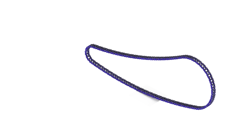
Features used:
- Sketch
- Blocks
- Extrude boss/base
- linear pattern
- circular pattern
- Fillet
- Mirror
- appearance
FRONT FENDER
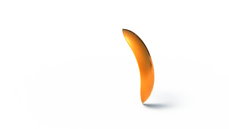
Features used:
- Sketch
- Revolve
- split
- extrude cut
- fillet
- appearance
REAR FENDER

Features used:
- Sketch
- Revolve
- Split
- Extrude cut
- Fillet
- Shell
- Appearance
FRONT WHEEL
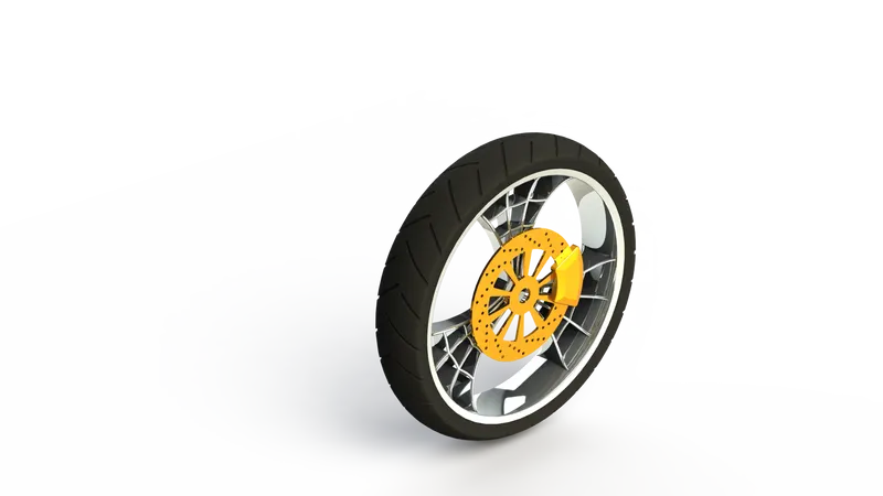
Features used:
- Sketch
- Revolve
- Extrude
- Extrude cut
- revolve cut
- circular pattern
- combine
- Fillet
- chamfer
- Appearance
REAR WHEEL
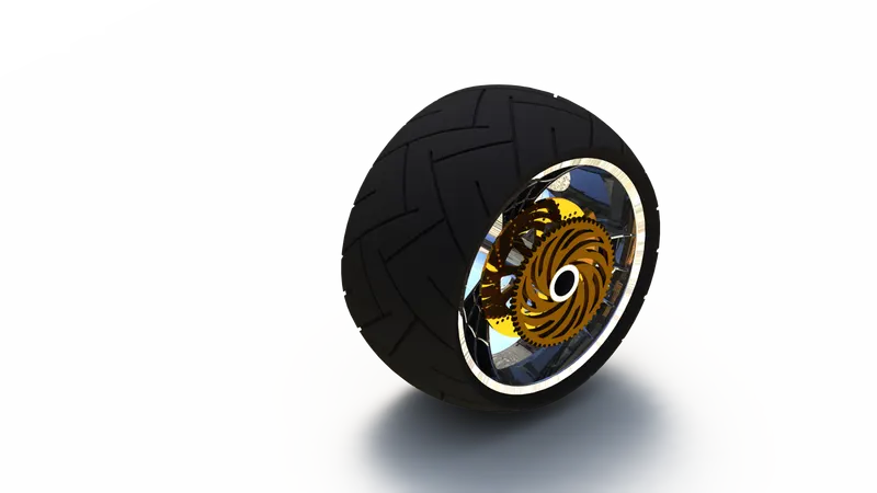
Features used:
- Sketch
- Revolve
- Extrude
- Extrude cut
- revolve cut
- circular pattern
- combine
- Fillet
- chamfer
- Appearance
OIL TANK
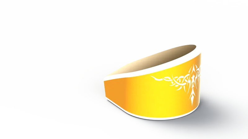
Features used:
- Sketch
- Extrude
- Combine
- Fillet
- Shell
- Extrude cut
GAS TANK
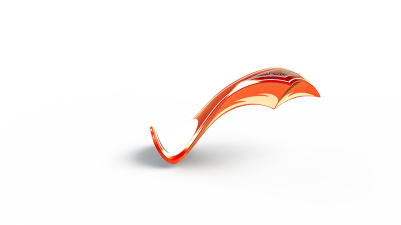
Features used:
- Sketch
- Surface sweep
- Surface trim
- Plane
- Project curve
- Surface loft
- Boundary surface
- Mirror
- Surface knit
- Split line
- Surface extrude
- Fillet
- Sweep cut
- Shell
FRONT FORK
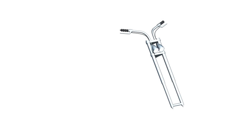
Features used:
- Sketch
- Extrude
- Combine
- Fillet
- Shell
- Extrude cut
CHASSIS
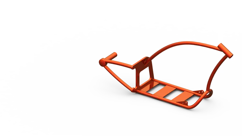
Features used:
- Sketch
- Project curve
- Sweep
- Mirror
- Extrude
- Extrude cut
- Fillet
- Chamfer
- Dome
- Plane
- Split
- Combine
- Revolve
ENGINE
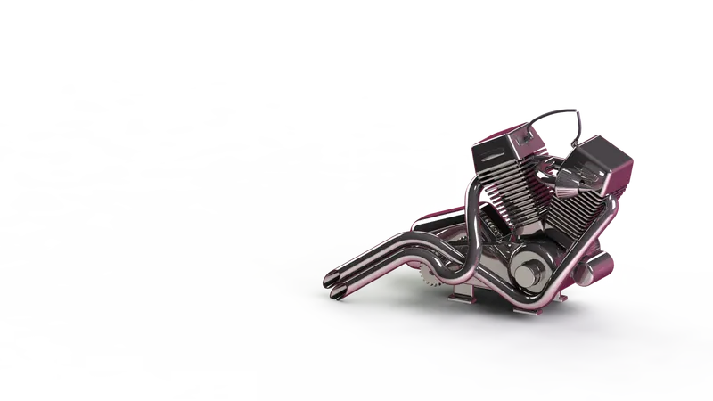
Features used:
- Sketch
- Extrude
- revolve
- plane
- circular pattern
- dome
- extrude cut
- chamfer
- fillet
- sweep
- mirror
- combine
- project curves
- split
- appearance
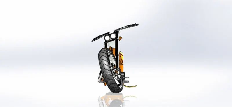
ASSEMBLY
COMMANDS USED:
- Insert component
- Mates
- Mirror component
MATES USED:
- Coincident
- Distance
- Concentric
- Angle
- Width
- Parallel
- Tangent
Screenshots:
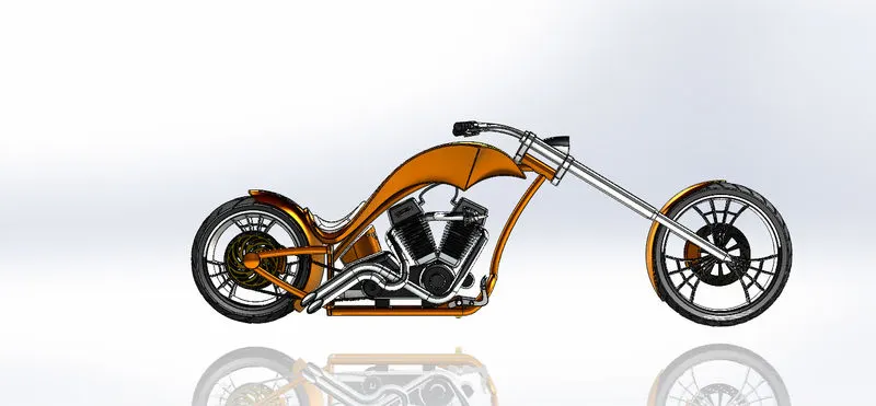
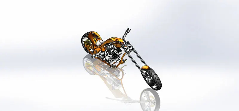
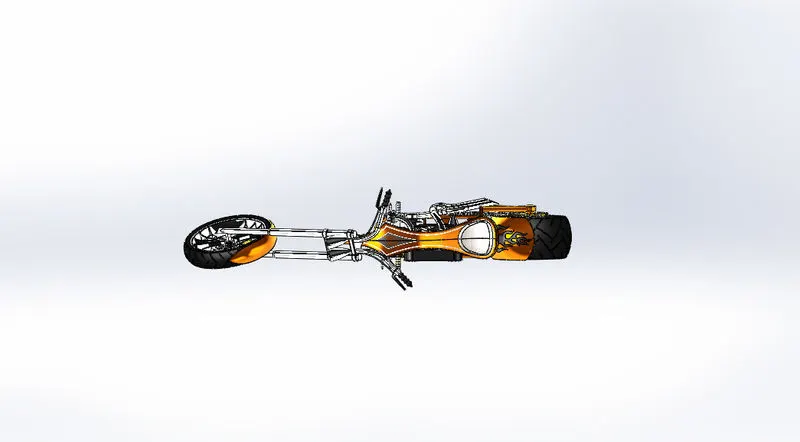
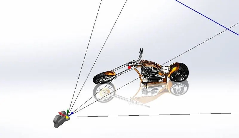
RENDERING
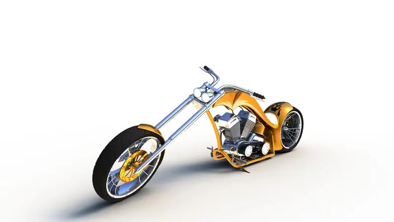
FINAL RENDER IMAGES
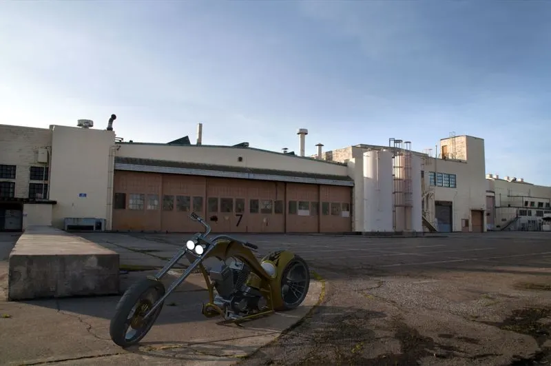
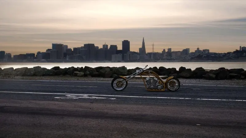
CONCLUSION
By doing this project I get to learn the concept of solid modeling, assembly, and rendering of a model using Solidworks and photoview 360