Project report on design and assembly of Chopper
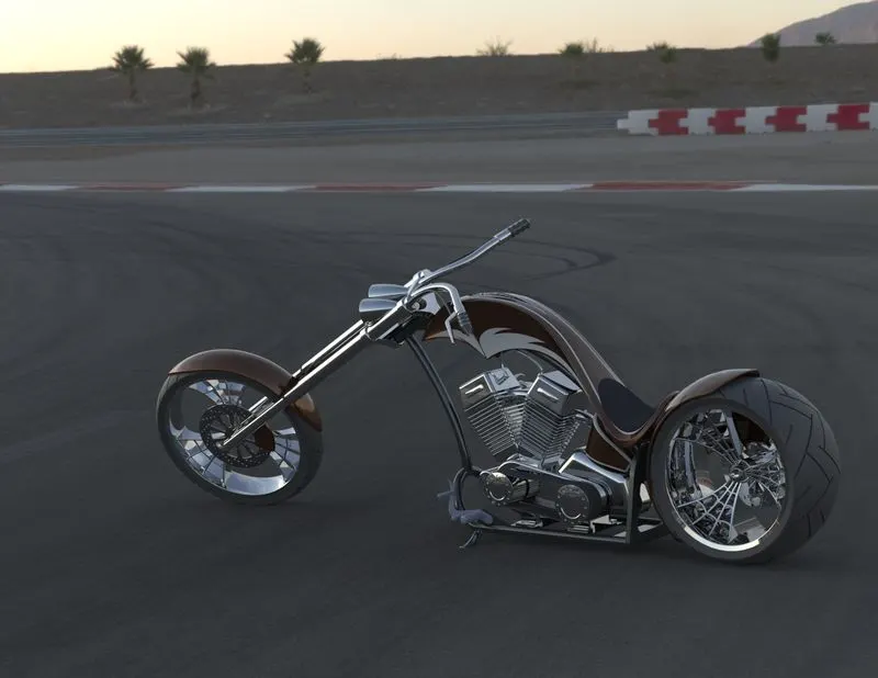
Title of project – Design, assembly and rendering of a model of a chopper motorcycle.
Objective – To get familiar with the interface and different functions as well as options in Solidworks for Part modelling, Assembly and Rendering by creating a cosmetic model of a Chopper.
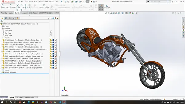
Introduction – A chopper is a type of custom Motorcycle which emerged in California in late 1950s. It has radically modified steering angles and lengthened forks giving it a stretched out appearance. In this project, we have tried to design a cosmetic model of the chopper. In this we have designed different components or parts of it like Front and rear wheels and fenders, Steering, Engine, Chassis, Fuel tank and other parts and assembled it in the end to get a lookalike of the chopper in Solidworks. Solidworks is a computer aided design (CAD) and Computer Aided Engineering (CAE) program. It is published by Dassault systems and is used largely in the manufacturing space by companies all over the world. We have used solidworks to design different parts of a model of the Chopper and assemble and render images of it in the end.
Design methodology/Approach (to be explained with the help of flowchart)
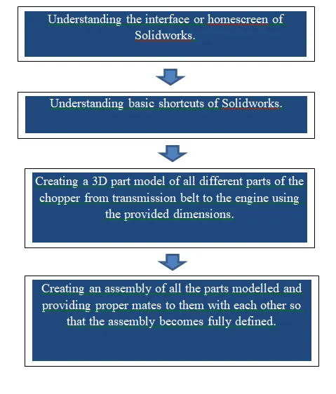
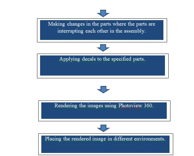
Description (Need to explain tools/ Features used while designing) along with images of part files.
The basic tools used were
- Sketch
- Smart dimensions – It helps applying dimensions to the entities easier and making the sketch fully constrained.
- Convert entities – helps projecting entities from a different plane to the current sketch plane.
- Offset entities – creates an offset for the selected entity.
- Trim entities – Deletes selected parts of the sketch.
- Mirror entities – Creates a similar pattern about the selected plane.
- Linear and Circular pattern – Creates a linear or circular pattern of the selected entity about the selected plane or axis.
- Features
- Extruded surface/boss/base/cut – Creates a solid body for the sketch in the defined direction.
- Revolved surface/boss/base/cut – Creates a solid revolve, mainly used for creating circular rods.
- Swept surface/boss/base/cut – Creates a solid surface along a given curved profile
- Lofted surface – creates a lofted surface along three references.
- Fillet – Creates a fillet along sharp edges of the given radius.
- Shell – Creates a hollow inside a solid block.
- Combine – Merges two solids after the extrude is done.
- Advanced tools used
- Split
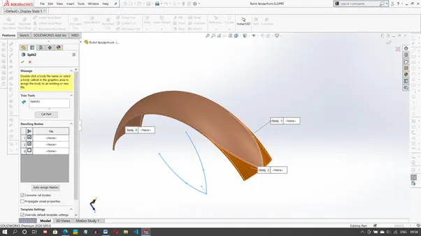
2.Projected curve
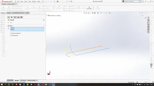
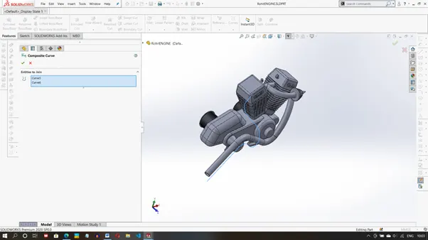
3.Composite curve
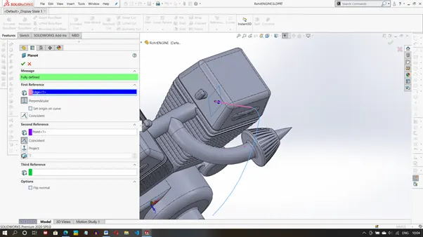
4. Reference Plane
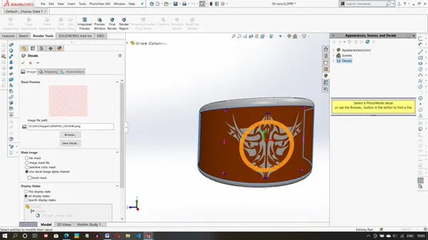
5. Edit Decals
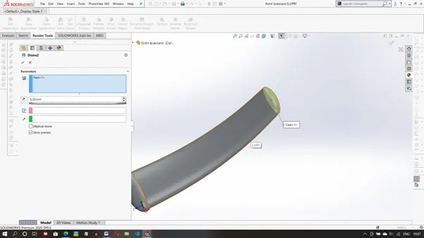
6. Dome
Five screenshots of assembly model
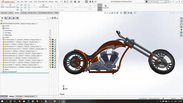
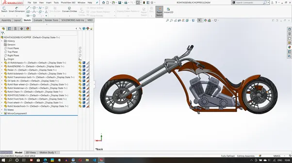
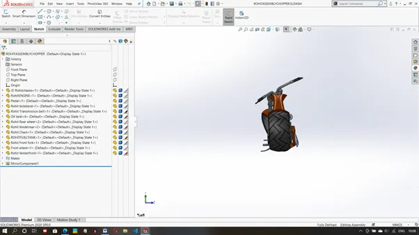
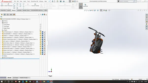
Indivisual Rendered parts
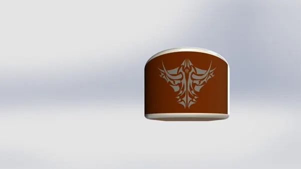
Oil Tank
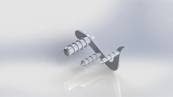
Pedal
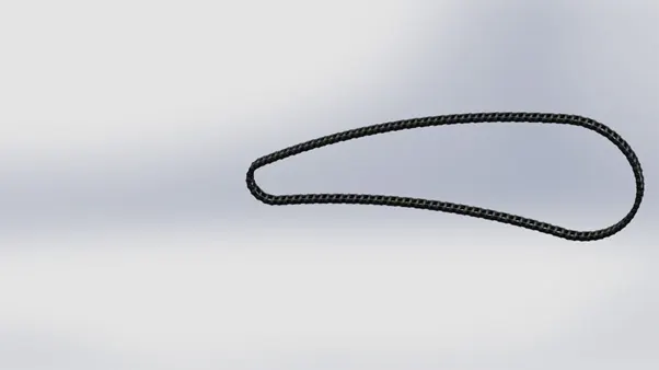
Chain
Front Fender
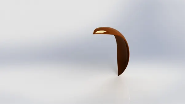
Rear Fender
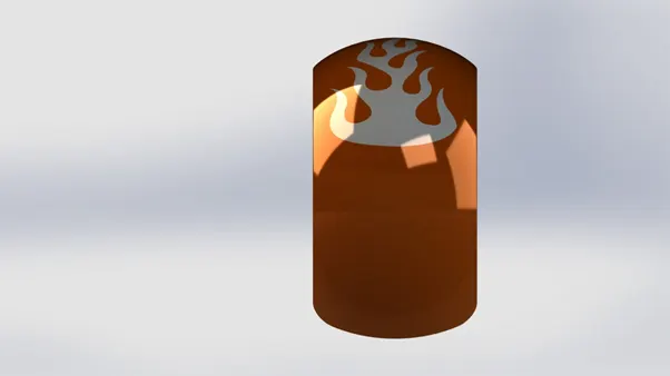
Front Fork
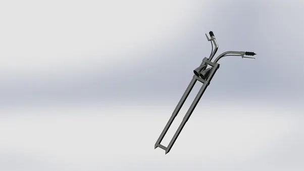
Kickstand
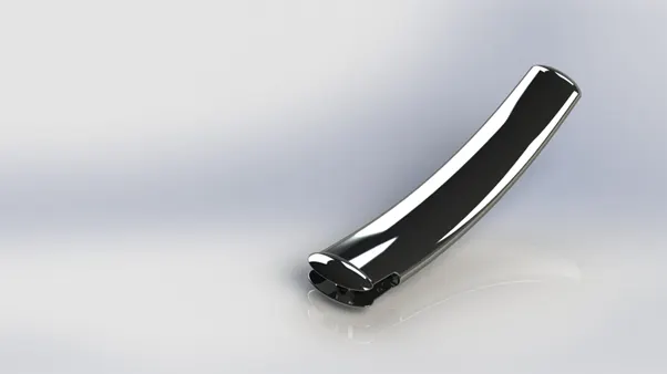
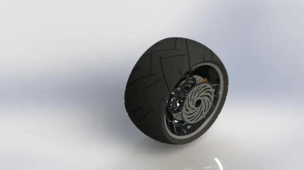
Rear wheel
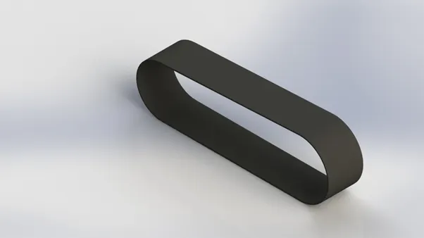
Transmission belt
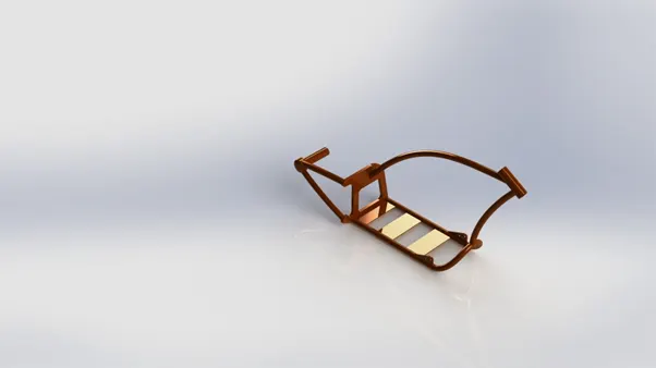
Chassis
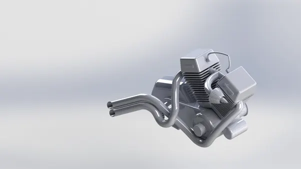
Engine
Fuel Tank
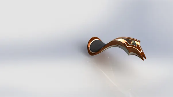
Rendered images
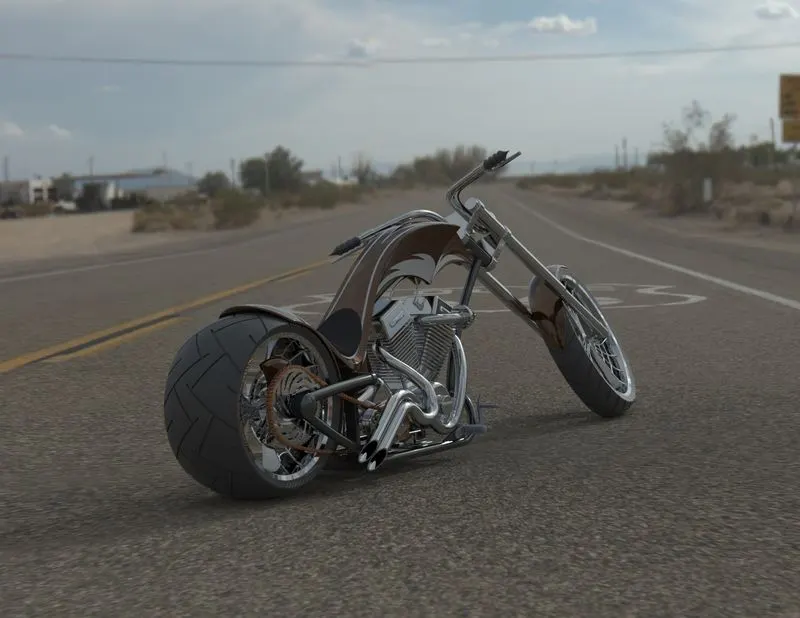
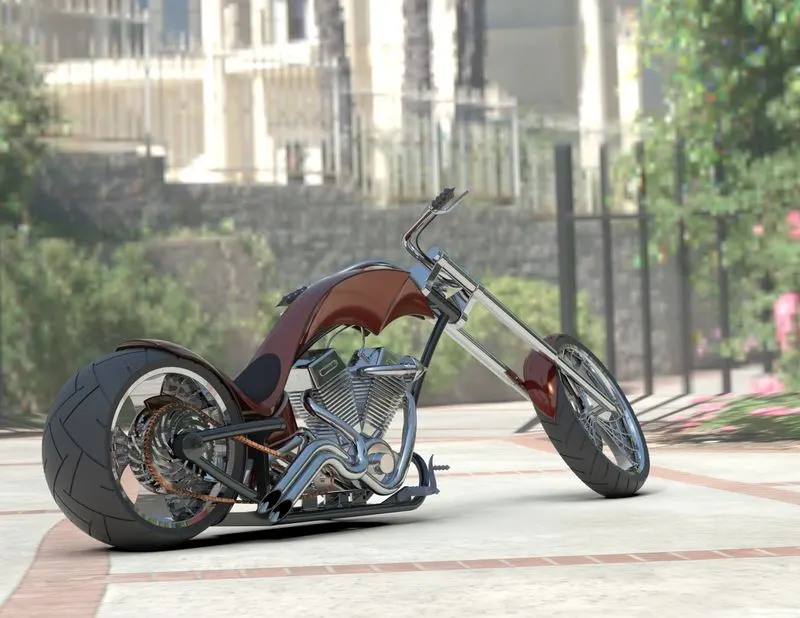
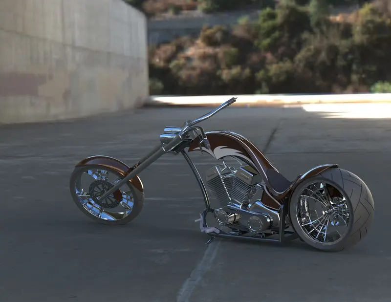
Conclusion
The Project helped in understanding different tools and features that can be used in solidworks to design, model, assemble and render different Machines similar to the chopper we designed. The project covered almost all the tools used in Solidworks and helped in understanding those tools due to practical application of the same.