Photo Realistic Rendering
Modelling of the American Chopper bike
Objective:
This project aims to help students develop fundamental skills in SolidWorks by designing the different parts of an American chopper bike and by assembling them. Additionally, this project aims to introduce students to 3D rendering techniques utilizing tools such as Photoview 360 and Solidworks Visualize.
Introduction
SolidWorks is a solid modeling computer-aided design (CAD) software that was made by Dassault Systèmes. The software allows you to model 3D objects by creating 2D sketches that can then be extruded in 3D. It also allows you to assign materials to a design and to add detailed features such as fillets, chamfers, threads, or domes. Moreover, it facilitates the creation of photo realistic renderings through its built-in tool photoview-360. The following development shows the methodology used to model and render an American chopper bike on SolidWorks.
Design methodology
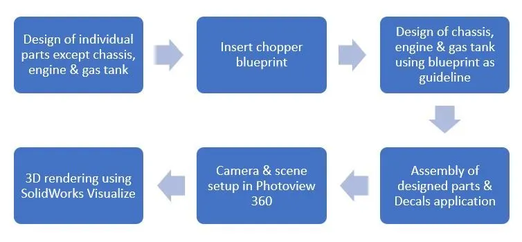
Description
Front wheel:
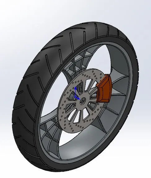
Features used in this design are:
- Sketch: 2D representation of the model
- Revolve: Allowed us to revolve sketch around an axis to create a 3D shape
- Boss Extrude: Allowed us to extrude a close 2D sketch and create a 3D shape.
- Cut Extrude: Allowed us to remove material from a 3D model.
- Cut Revolve: allowed us to remove material by revolving a closed profile along an axis.
- Combine: Allowed us to combine multiple intersecting bodies.
- Circular Pattern: Allowed us to reproduce a feature/sketch in a circular pattern.
- Fillet & Chamfer: Allowed us to replace hard edges by smooth edges.
Rear Wheel:
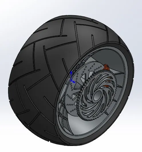
Features used in ths design are:
- Sketch
- Revolve
- Boss Extrude
- Cut Extrude
- Cut Revolve
- Combine
- Circular Pattern
- Fillet & Chamfer
Front Fender:
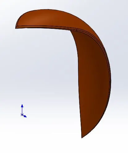
Features used in ths design are:
- Sketch
- Revolve
- Split: Allowed us to remove undesired features on intersecting objects.
- Fillet
Rear Fender:
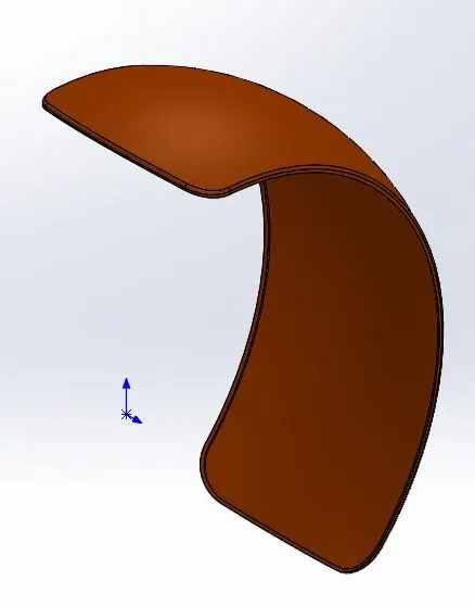
Features used in ths design are:
- Sketch
- Revolve
- Split
- Fillet
Front Fork:
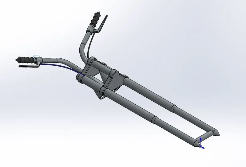
Features used in this design are:
- Sketch
- Revolve
- Boss-extrude
- Linear pattern: Allowed us to reproduce a feature/sketch in a linear pattern.
- Cut-extrude
- Cut-revolve
- Body-Move/copy: allowed us to mirror a solid body with respect to an axis.
- Sweep: Allowed us to sweep a profile along a curved path.
- Combine
Chassis:
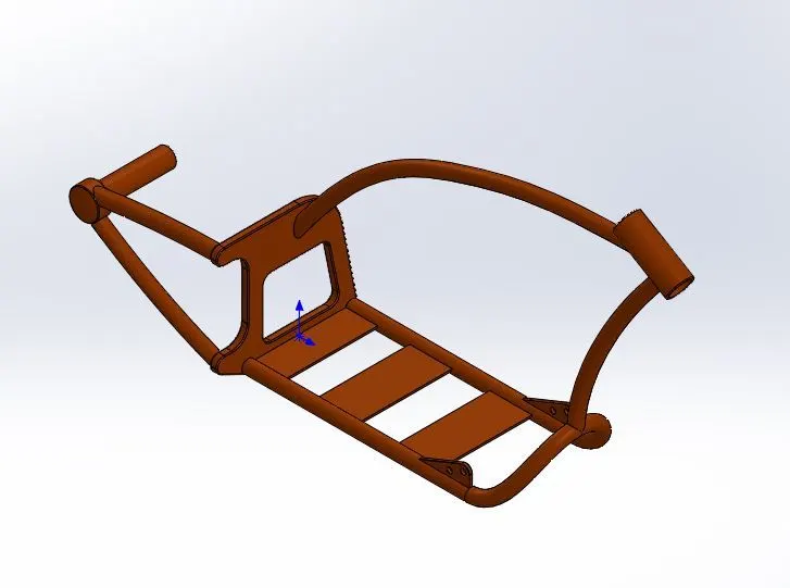
Features used in this design are:
- Sketch
- Projective curve: Allowed us to create a curve/path by combining two curves in different planes.
- Mirror
- Boss-extrude
- Sweep
- Split: Allowed us to remove undesired features on intersecting objects.
- Reference plane: Allowed us to create an advantageous plane to sketch/create a feature.
- Combine
Engine:
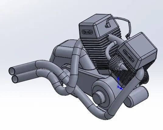
Features used in this design are:
- Sketch
- Boss-extrude
- Revolve
- Circular Pattern
- Cut-extrude
- Mirror
- Split
- Combine
- Sweep
- Projected curve
Gas Tank:
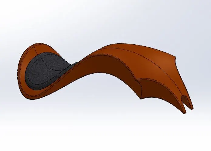
Features used in this design are:
- Sketch Picture: Allowed us to bring in blueprint as a guideline.
- Surface sweep: Allowed us to create a sweep by moving a 2D profile along a 2D/3D sketch path.
- Surface Loft: Allowed us to create surfaces using 3D curves
- Projected curve
- Boundary surface: allowed us to create tangent/curvature continuous surfaces.
- Surface-Knit:
- Cut-sweep: Allowed us to cut the model by sweeping a closed profile along a path.
- Shell: Allowed us to create a shell in a model with a definite thickness.
Oil Tank:
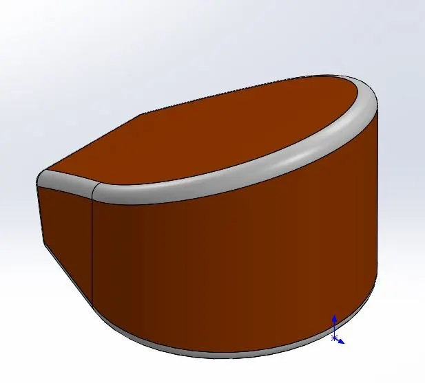
Features used in this design are:
- Sketch
- Boss-extrude
- Combine
- Fillet
- Shell
Chain:
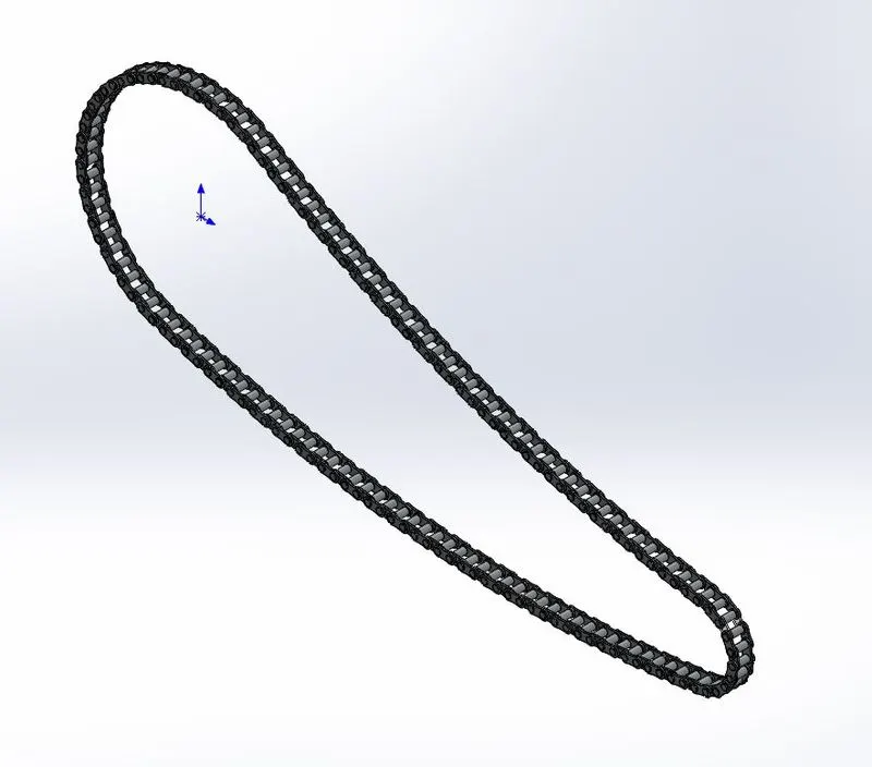
Features used in this design are:
- Sketch
- Boss-extrude
- Circular Pattern
- Mirror
Kick Stand:
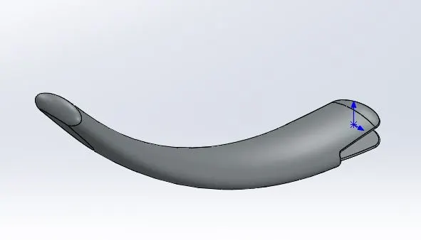
Features used in this design are:
- Sketch
- Loft
- Dome: Allowed us to create a dome
- Split
- Cut-extrude
Transmission Belt:
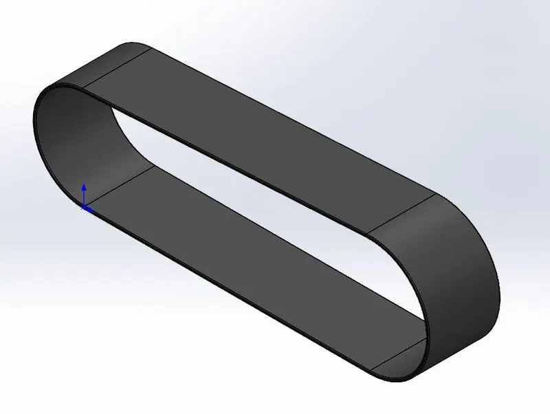
Features used in this design are:
- Sketch
- Boss-extrude
- Fillet
Pedal:
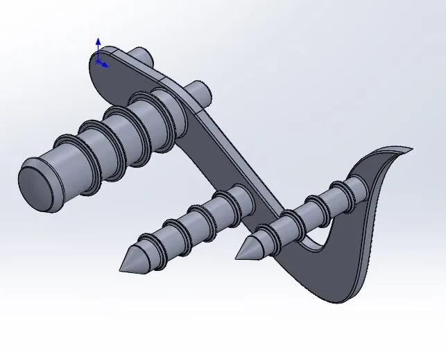
Features used in this design are:
- Sketch
- Boss-extrude
- Revolve
- Linear Pattern
Assembly of chopper:
Once all the parts described above were designed, we began the assembly of the chopper in a SolidWorks assembly part file. We utilized the mate features (distance, angle, LimitAngle, width, concentric, coincident, tangent, position) to combine parts and fully define the assembly. Then, we applied the decals on the chopper. The following pictures show the result:
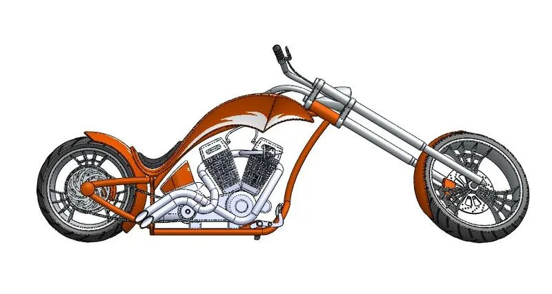
Figure 1: Assembly - Side View
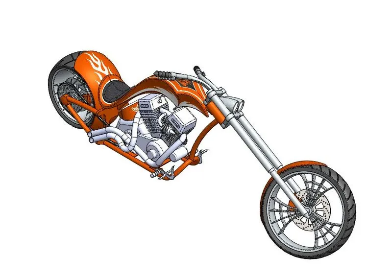
Figure 2: Assembly - Isometric view
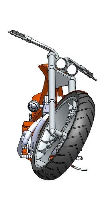
Figure 3: Assembly - Front view
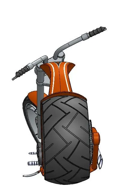
Figure 4: Assembly - Back view
Rendering:
After we completed the assembly of the chopper, we turned on photoview 360 and we setup a camera and a scene to start the rendering process. To make the model more realistic, we made sure that the bottom plane of both wheels matched so that the chopper appeared to be on the floor when we render it.
- Photoview 360: The camera was directly aimed at the chopper with the perspective and depth of field features turned on. The environment was plain white, and the shadow effect was reduced to get softer shadows. The camera view was saved in the view orientation tab to allow us to switch between the 3D model and the scene. A preview of the rendering is shown below.
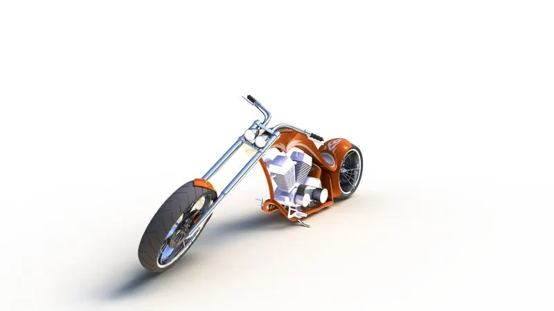
Figure 5: Photoview 360 chopper rendering.
- SolidWorks Visualize: Solidworks Visualize is a stand-alone rendering software that is more powerful than photoview 360. Though the camera and scene setup is approximately the same. We brought the chopper assembly into Solidworks visualize and we reapplied paint appearances to it. Then, we setup a camera and an environment (HDR environment). Once we were satisfied with the scene, we rendered the chopper. Below are a few render examples.
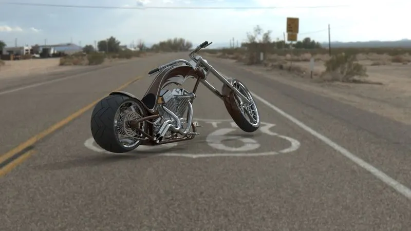
Figure 6: SolidWorks Visualize render 1
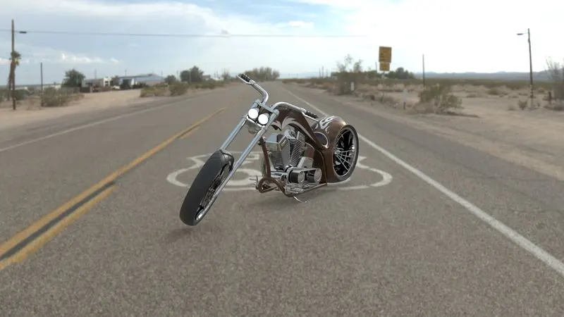
Figure 7: SolidWorks Visualize render 2
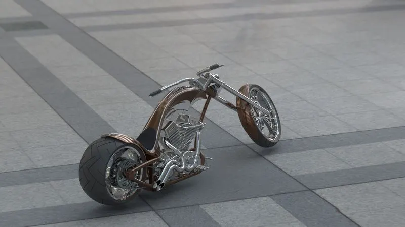
Figure 8: SolidWorks Visualize render 3
Conclusion:
This project is a success. We were able to successfully design and render the American chopper bike using SolidWorks part files, assembly part files, photoview 360 and SW visualize.