Photo Realistic Rendering
Modelling and Rendering of A customised American Chopper
Objective:
- To model an American Chopper part by part using Solidworks.
- Assemble the different parts together.
- To render it using Photoview 360 and Solidworks Visualize.
Design Methodology:
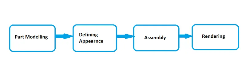
I will be modelling an American Chopper part by part and then assembling it. Rendering will be performed using Solidworks Visualise and Photoview 360.
Features Description:
There were n numbers of feratures used to model and assemble the American Chopper and render it.They all are as mentioned,
Solid Bodies:
Sketch:
- Sketch feature allows to sketch the model in 2D using various shapes such as Line, Rectangle, Circle, Arc, Ellipse, Spline, Point etc. These are also called as entities and are the base to your 3D model.
Convert Entities:
- Convert Entities is an option which allows to convert a pre sketched entity in a different sketch or plane and this converted entity can be used as a reference to the new sketch.
Offset Entity:
- Offset feature helps in offseting an existing entity in a new sketch.
Extrude Boss/Base:
- It converts a 2D sketch into a solid body by generating a block of the 2D sketch entities.
Lofted Bose/Base:
- Loft helps in making a solid model of 2 different shapes.
Swept Boss/Base:
- Swept is a feature which helps in sweeping a 2D sketch along a defined path creating a solid model.
Extruded Cut:
- Extruded cut helps in making a cut(hole) in a Solid body.
Revolved Boss/Base:
- Revolved feature helps in revolving a 2D sketch along an axis making a Solid body.
Fillet/Chamfer:
- Fillet/Chamfer helps in creating the respective feature along the corners or edges of the 2D sketch or solid body.
Pattern:
- This fetaure helps in creating a linear or circular pattern of a 2D sketch or a solid body.
Mirror:
- This feature helps in creating a mirrored sketch/body along a mirror plane.
Projected Curves:
- This feature helps in creating a curve which has its refernce from 2 different plane,There are 3 conditions for a projected curve to exist,
- The 2 different curves should be in 2 different planes.
- The sketch curves should start and end at the same point.
Reference Geometry:
- This feature helps in creating a plane with reference to any sketch point/entity/plane.
Combine:
- This feature helps in combining/deleting or keeping the common part of the selected solid bodies and convert it into a single solid body.
Split:
- This feature is similar to the combine feature but it is different in a way that instead of solid bodies,an edge is used.
Surfaces:
Extruded Surface:
- This feature helps in extruding 2D sketches as Surfaces as per the provided criterion.
Swept Surface:
- Swept surface feature helps in creating a surface along a desired path provided by the user.
Lofted Surface:
- Lofted surface feature helps in joining two surfaces of different shapes.
Filled Surface and Boundary Surface:
- These features are pretty much similar as they are used to close an open 3D body. The difference is that boundary surface makes a surface between two different profiles or edges, whereas the filled surface just fills the boundary irrespective of profile.
Trim Surface:
- This feature helps in trimming the surface that are not required and make a tailor fit surface.
Extended Surface:
- This feature helps in extending a surface either ways.
Knitted Surface:
- This is one of the most important feature of surfaces,which knits all the selected surfaces and has an option to convert it onto a solid body.
Parts Modelled for American Chopper:
- Chain
- Chassis
- Engine
- Front fender
- Rear Fender
- Gas Tank
- Front Wheel
- Rear Wheel
- Transmission belt
- Side Stand
- Pedal
- Fuel Tank
- Front Fork
Part Description and Feature used:
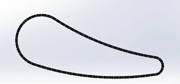
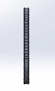
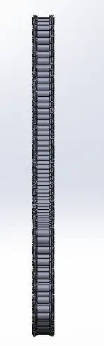
Chain:
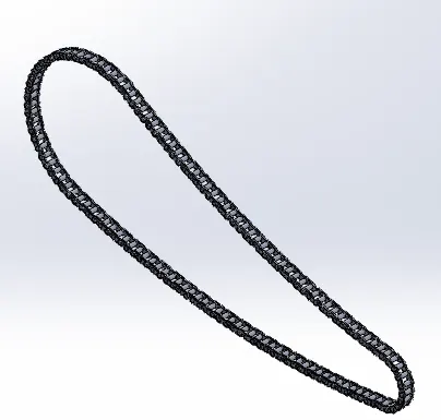
Chain is a part that transfer the power from the engine to the wheels and is connected using the sprocket.The features used were Extruded Boss/Base,Fillet,Projected Curves,Curve Pattern and Mirror.
Transmission Belt:
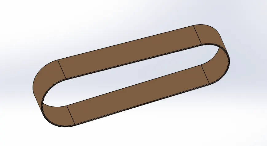
Transmission belts are connected between to shafts to tranfer power from one shaft to another.It is ususally made of flexible material to absorb shocks while transfering power.The features used were Extruded Boss/Base and Fillet.
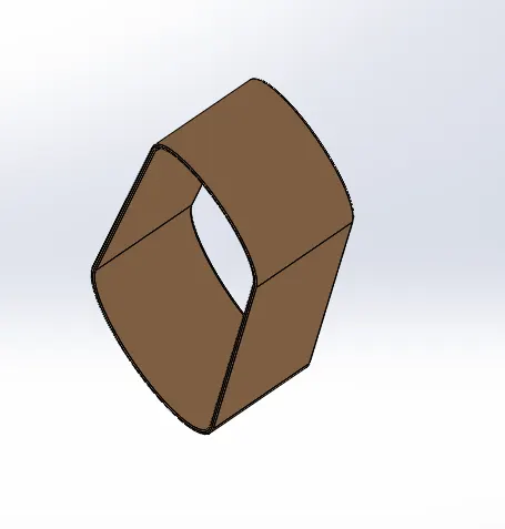
Side Stand:
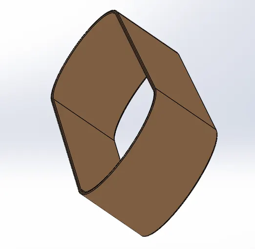
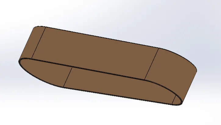
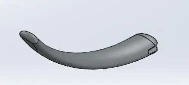
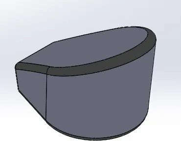
A side stand is that part of the bike on which the hole body rests when parked.Side staands are designed in such a way that they carry the load of the bike and are located at the centre of gravity of the bike.The features used were Extrude Boss/Base,Loft,Dome,Extrude Cut,Split,Fillet.
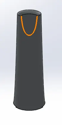
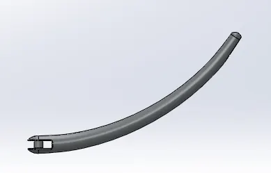
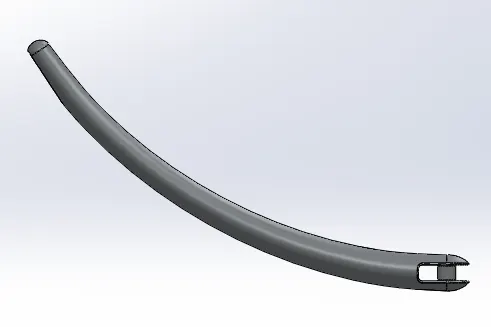
Gas/Oil Tank:
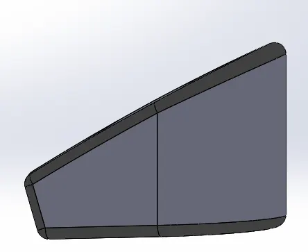
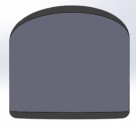
A Gas/Oil tank is a container that holds the fuel used in by the bike.It is the reservoir of the bike.
The features used were Extrude Boss/Base,Shell,Combine,Fillet.
Pedal:
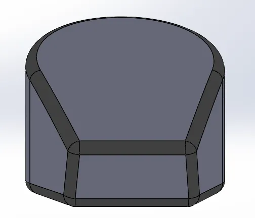
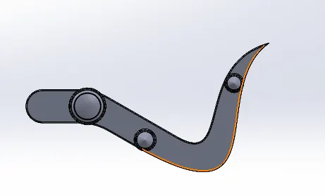
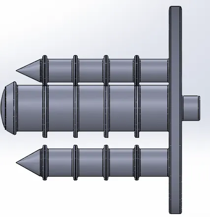
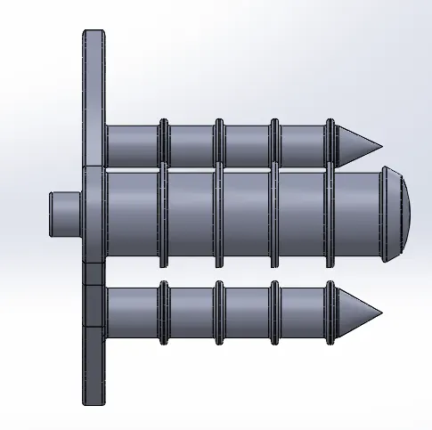
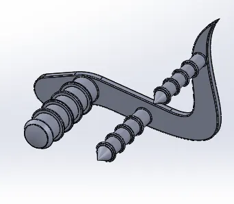
Pedal is that part where the foot of the rider rests and the gears are shifted.It is located next to the Engine.The features used were Extrude Boss/Base,Linear Pattern,Revovled Boss/Base,Dome,Chamfer,Fillet.
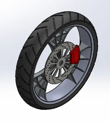
Front Wheel:
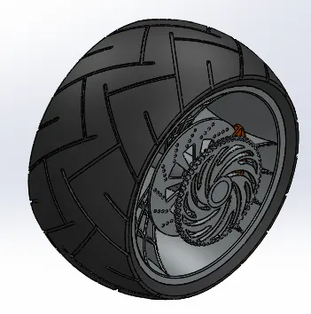
The Front Wheel is one of the sources of converting the linear motion generated by engine to circular motion. The front wheel is also responsiblr for turning the vehicle.The features used were Extrude Boss/Base,Circular Pattern,Revolved Cut,Combine,Extrude Cut,Fillet,Chamfer.
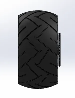
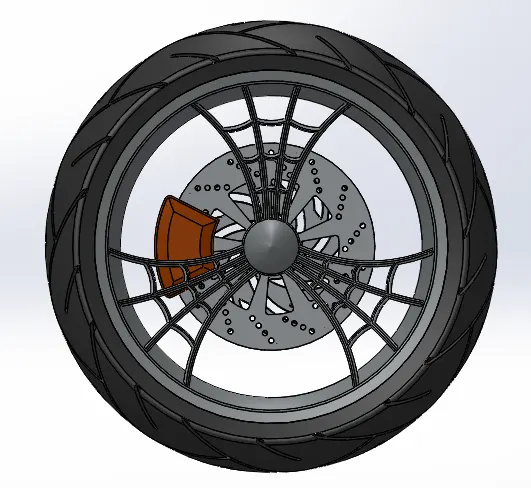
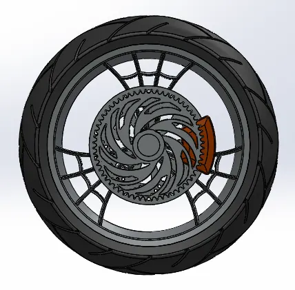
Rear Wheel:
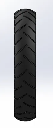
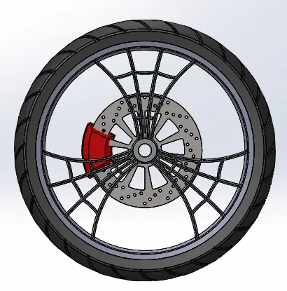
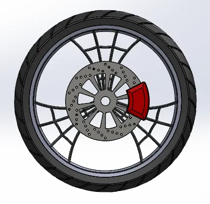
Rear Wheel is the part which moves the vehicle forward as engine is connected to it.It is connected to all other Sub systems.The features used were Extrude Boss/Base,Circular Pattern,Revolved Cut,Combine,Extrude Cut,Fillet,Chamfer.
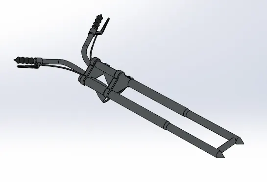
Front Fork:
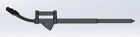
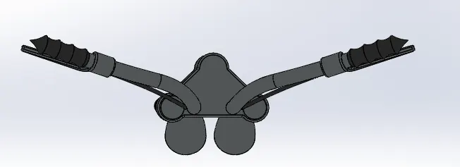
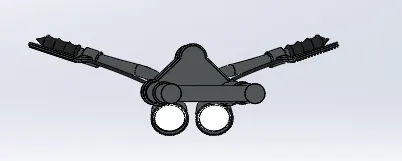
Front Fork is nothing but the handle and the remaining part of it having suspension system and front wheel.The features used were Swept Boss,Extrude Boss/Base,Extrude Cut,Dome,Projected Curve,Combine,Revolved Boss/Base,Combine,Mirror,Chamfer,Split,Revolve Cut
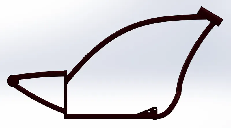
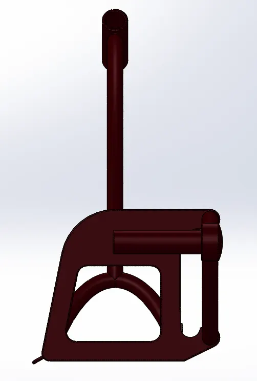
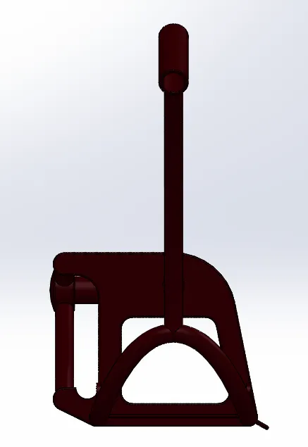
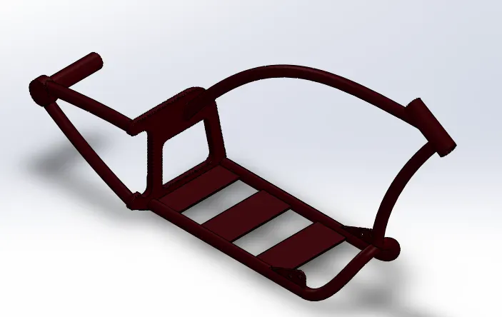
Chassis:
Chassis is teh body of the bike where all the sub systems sit in.It is the skeleton of the bike.The features used were Swept Boss, Extrude Boss/Base,Extrude Cut,Dome,Projected Curve,Combine,Revolved Boss/Base,Combine,Chamfer,Split,
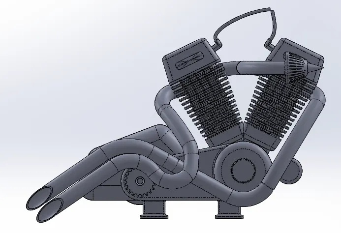
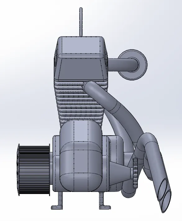
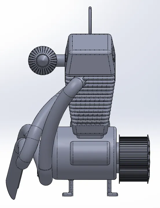
Engine:
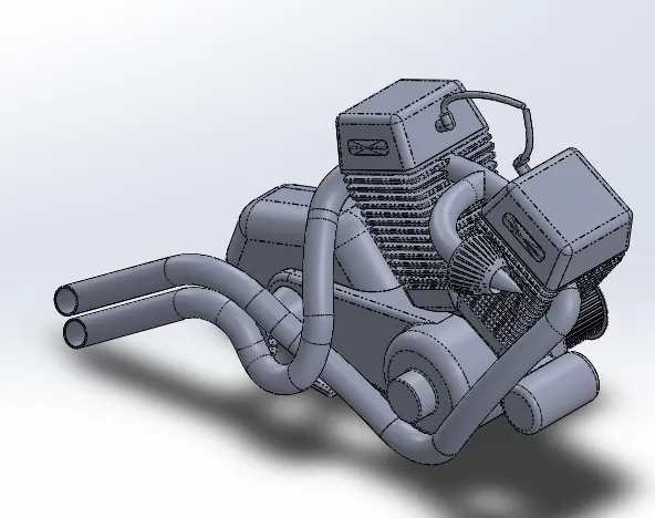
Engine is the part which generates mechanical energy from Chemical energy. of the fuel.It is the heart of the bike.The features used were Swept Boss, Extrude Boss/Base,Extrude Cut,Dome,Projected Curve,Combine,Chamfer,Split,Fillet,Linear Pattern,Circualr Pattern,Composite curve.
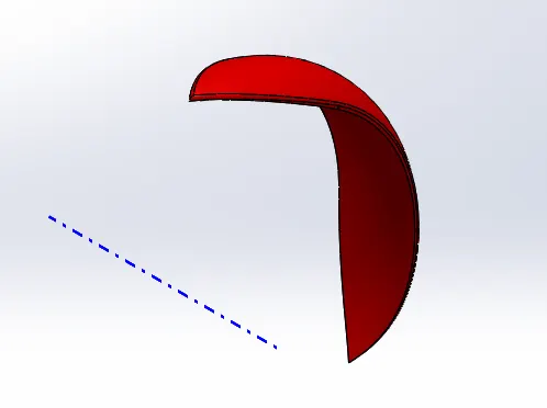
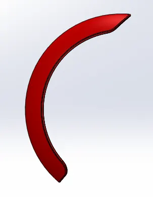
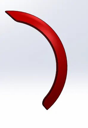
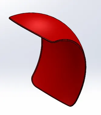
Front and Rear Fender:
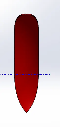
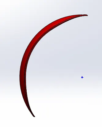
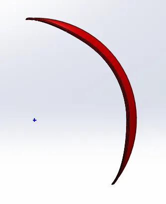
Front fender is refereed to the mudguard. The features used are Revolved Boss/Base,Split,Fillet.
Front:
Rear:

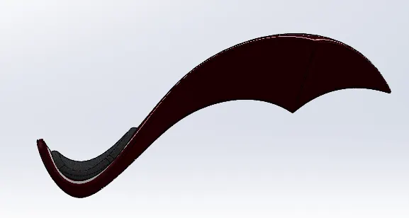
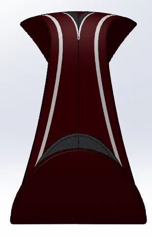
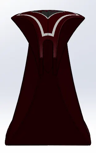
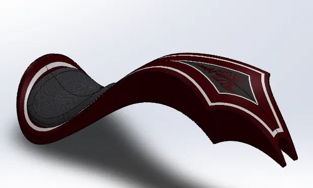
Fuel Tank:
Fuel Tank is nothing more than a storage as thename suggests. The features used are Surface loft,Surface Knit,Projected curve,Swept surface,Mirror,Plane,Swept Cut,Split,Fillet.
Assembly:
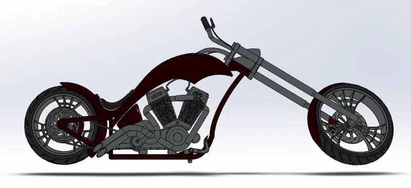
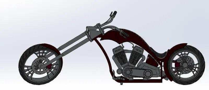
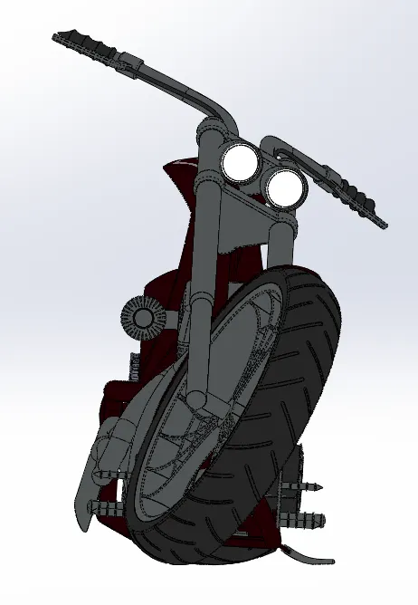
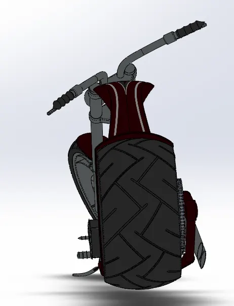
The parts are brought in one by one starting from chasis and are assembles using the "Mates" feature.
Features Used:
Mates:
This feature helps in creating realations between Edges,surface and planes to get a final assembly with ease.
Rendering:
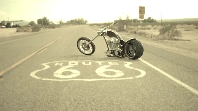
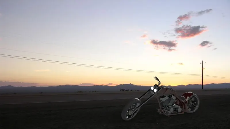
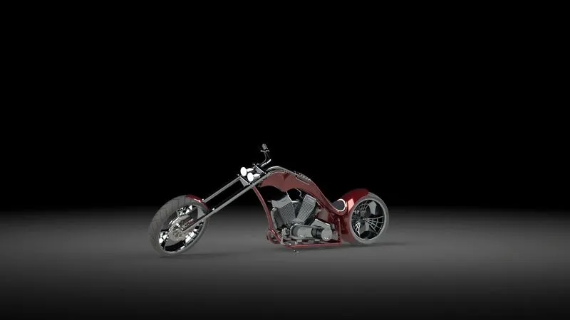
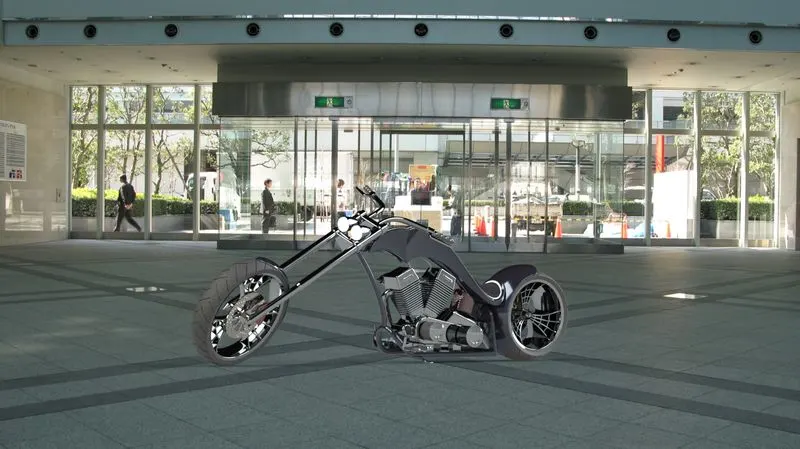
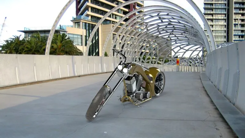
Real view rendering is done using Photoview 360 and Solidworks Visualize by setting up variou parameter like Camera angle, Backgrounds, Environment Luminous intensity, Vehicle appearnces and materials etc.
Conclusion:
- The different parts of the American Chopper are modelled.
- They are assembled together by creating mates.
- The Bike is rendered using Solidworks Visualize and Photoview 360.