Photo Realistic Rendering
Title :- Modelling and Assembly of Chopper.
Objective :- The objective of the project was to get familiar with the solidworks interface , different solidworks tools and features using all that for modelling all components of the chopper in a efficient way , later doing the assembly and rendering it in a realistic environment.
Introduction :- SOLIDWORKS is a CAD software that lets designers quickly sketch out ideas , experiment with features and dimensions and produce models. Here we are going to see the model of a American chopper with its assembly and final render.
Design Methodology :-
|
Sketching of the part in 2D on respective plane |
|
Adding relations to the sketch. |
|
Making the sketch fully defined by adding dimensions |
|
Using features like extrude , revolve , cut, pattern , sweep etc |
|
Using of reference plane or projected curve for other sketches |
|
Later adding fillet/chamfer to respective parts |
|
Adding appearance to the components |
|
Saving the File in respective location. |
|
Later adding those saved files in assembly to create the whole assembly model by adding mates |
|
Setting cameras and pre rendering in photoview 360 |
|
Using Solidworks visualize for making a realistic photo render in fast way. |
Description :-
- It started with the interface of SOLIDWORKS , adding some handy shortcut-keys , getting familiar with all the features and tools.
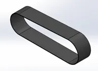
- Firstly I started by modelling the Transmission Belt which was the foundation of my solidwork knowledge as it included all the basics things like adding relations , extruding , adding fillets etc which I needed to get started with solidworks program.
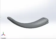
- Next I made the model of the Kickstand where I got to learn some advance sketching techniques like creating a spline , adding sweep , and applying domes to the parts.
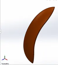
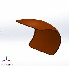
- Further it was the Front Fender & Rear Fender of the chopper , which was made with features used in previous components and also some new features like revolve and spilt and shell.
- Chain was the next component of the chopper , which was one of the complicated and difficult component in this project , here I learned some additional features like a sketching on a curve driven path , making of blocks , later adding those block as per the sketch , and mirroring the whole chain after completing a single side. Also I learned to group up similar solid bodies in a single folder to make any future changes easy.
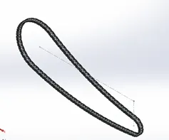
- Next I modelled the Oil Tank , which was based on the previous known feature with a new feature called the combine feature which was used to make a single solid body as a whole with the reference of 2 solid bodies
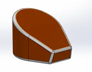
- Pedal was the next component of the chopper , where we saw a new feature the Linear pattern and rest of based on the basic knowledge from previous components
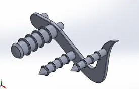
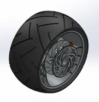
- Next was the Front and Rear Wheel of the chopper which also a bit complicated but here I learned how to use the existing feature in different ways. Firstly I made the central hub , then the rims , rotor , brake calliper , sprocket on the rear wheel and the tyre on the outer surfaces. I have many errors also in this process like the sketch was not getting fully defined , cut extrude was showing rebuild errors but by checking every sketch and the dimensions the errors were solved
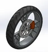
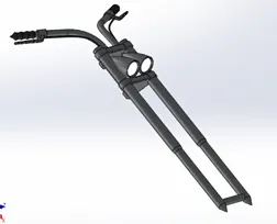
- Further I designed the Front Fork , which was very interesting component as it was totally depended on the revolve and mirror feature. Later I also learned how to add light effect to the headlights from the appearance tab. Making the brake wires using the sweep feature and combining the whole as a single solid body.
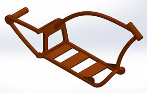
- Next was the Chassis of the chopper on which all the components were going to be assembled . In this we used a blueprint of the chopper as a reference to make the whole chassis. By adding the chopper image and setting its transparency made it very easy to understand the modelling process. Here I also the learned the Projected Curve feature which used two sketches to make a required curve. Combine and Split feature was used very much in this component.
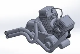
- Engine the most complicated component in this project and literally used all the features in its modelling. In this process the blueprint was again used which helped a lot in getting the perfect idea of the dimensions. All features like liner pattern for the fins , projected curve for the exhaust pipe and air intake , extrude , fillets , chamfers , circlular pattern for the sprocket was used. I faced many error while making this model as in the projected curves of the exhaust pipes
- Gas Tank was the next component and was made using complex surfaces and different sketching techniques and here I came across lot of new features and tools. Blueprint was also used as a reference in this process. In this mainly surface features such as surface loft , boundary surface , surface trim , surface knit , surface sweep was used. The making of the tank surface , extruding the surface for the seat , cutting section for the front fork was very interesting .
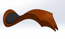
- Next was the Assembly of the chopper. Firstly I imported the chassis on to which every other component was going to attach with the respective mates. So by fixing the chassis I started importing the engine , wheels , chain , transmission belt , front fork , chain , fenders. There were many errors while mating the components which over defined the sketch, so it was necessary to suppress them for a while and continue adding other updates. Also mating the kickstand to the bottom plane so the bike looks as if it is leaning on the stand. There were some part where the components were overlapping each other which was fixed by hiding the other components and changing the sketch. Adding decals on the gas tank , oiltank and rear fender. Then adding the background as a environment then setting the camera according to the needed view. Then using Photoview 360 for getting a idea how does the chopper looks in with the environment setting.
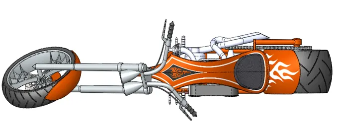
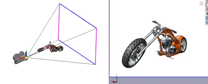
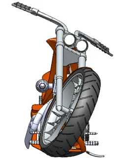

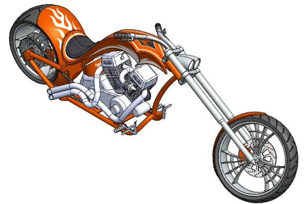
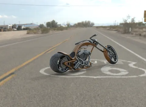
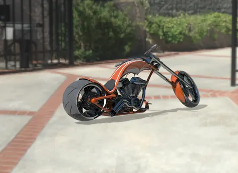
- Then using Solidworks Visualize to add the background image and placing the assembly in it. Adjusting the colors , brightness , gamma value and making the chopper look as realistic as possible and checking it using the fast render method and again tweeking some values and getting the final render.
Conclusion :-
- Got thorough knowledge of solidworks program from basics to advance.
- Variety of examples and challenges made it very interesting.
- Easy to make prototype design within less time.
- Realistic renders can be made to check how the product looks in real life
( NOTE :- MY LAPTOP IS VERY OLD SO THE RENDERS ARE NOT VERY GOOD I HAVE SAVED WHICH EVER WAS THE BEST ACCORDING TO ME. I ALREADY INFORMED IN THE SUPPORT SESION THEY SAID TO MENTION IT IN THE REPORT. )