Photo Realistic Rendering
MODELLING AND RENDERING OF THE AMERICAN CHOPPER
OBJECTIVE:
- To create different parts of an American chopper using different tools and commands available in Solidworks to the best of its Originality.
- To assemble all the parts created to set up the final design of the Chopper.
- To render quality Images of the American Chopper in different Environments.
INTRODUCTION:
Being a fan of the American reality show 'American Chopper' I was highly motivated in designing and completing this project and here is the project report of how I went about it.
METHODOLOGY:
Plan of action of the Designing and Rendering process of the chopper is:
- Modelling various components
- Assembling the components created
- Serring up camera,Lights,Envirinment,etc for the render
- Using Photoview 360 and Solidworks visualize to get quality renders.
The commands and features used in this project are:
- 2D SKECH
- PROJECT CURVES
- OFFSET
- TRIM
- CONVERT ENTITES
- BOSS EXTRUDE
- REVOLVED BOSS
- SWEPT BOSS
- EXTRUDE CUT
- REVOLVED CUT
- LOFT
- DOME
- FILLET
- CHAMFER
- COMBINE
- EXTENDED SURFACE
- RULED SURFACE
- OFFSET SURFACE
- SURFACE FILL
- BOUNDARY SURFACE
- LOFTED SURFACE
- SHELL
- MIRROR
- SMART DIMENSION,ETC.
COMPONENTS MODELLED AND RENDERED:
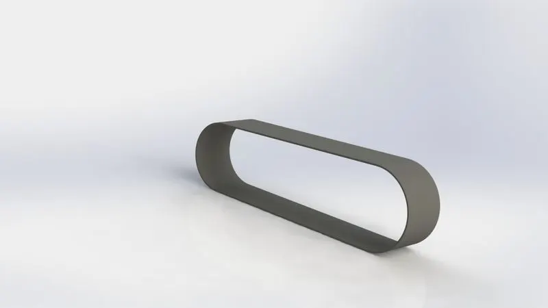
1)TRANSMISSION BELT
- I was introduced to various sketch tools such as smart dimensions,splinemcircle tool,trim tool,fillets,Rc with midpoint,Arc with two and three points.
- Got acquainted with relations in sketches such as Tangential,Horizontal,Vertical,Coincident,etc.
- Applied Matte Rubber material from Appearence toolbox
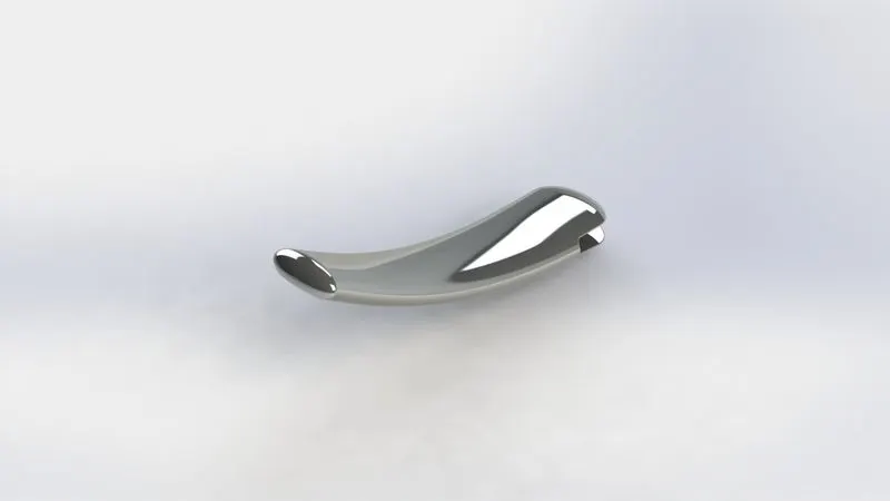
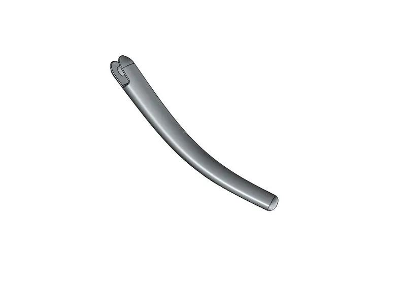
2)KICK STAND
- While designing this tool I was introduced to the spline and how to apply weights to it.
- To apply solid to the sketch I used the Lofted Boss
- Material applied-Chromium plate.
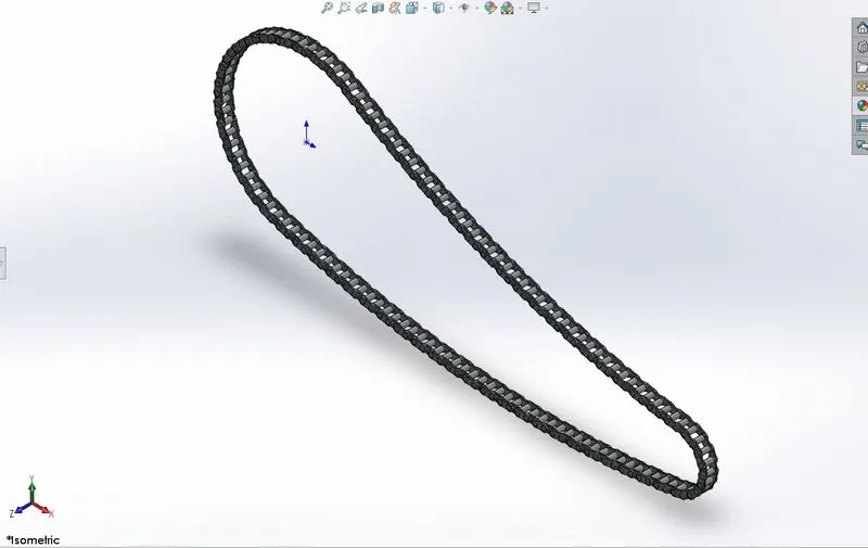
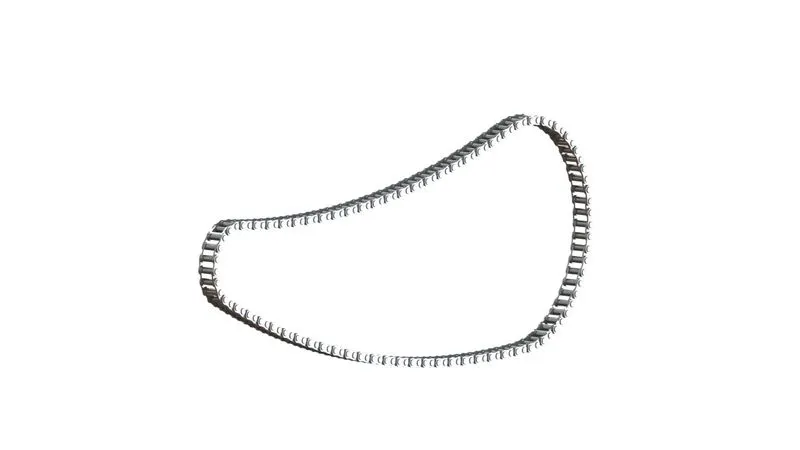
3)CHAIN
- Got acquainted with making Sketch blocks and how to reuse them during the sketch phase.
- The sketch blocks created for this is pin and chain plates.
- Used 'curve driven pattern' tool for the completion of the chain model.
- Material applied-Chromium plate
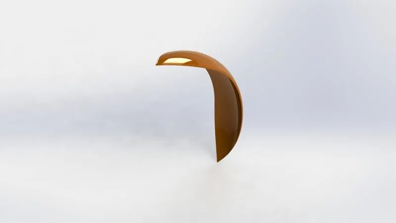
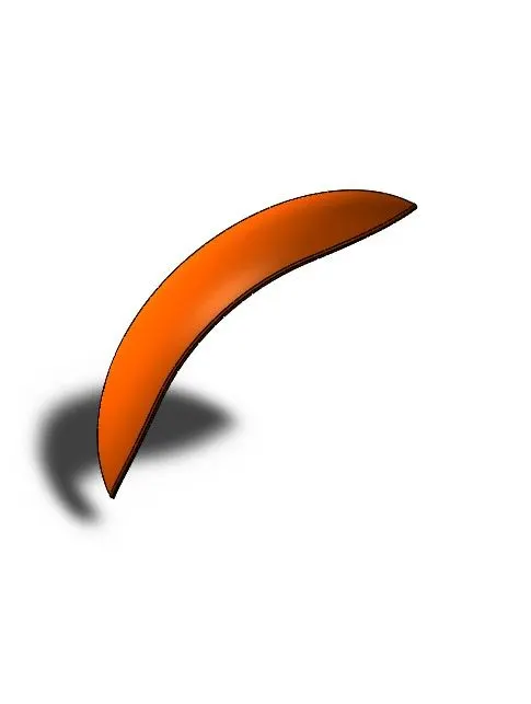
4) FRONT FENDER
- Learned to use such as 'Revolved Boss/Base',split tool,etc.
- Used three point arc,covert and trim entities feature,etc.
- Used fillet tool for filleting the sharp edges on the fender
- Paint colot used-Siena
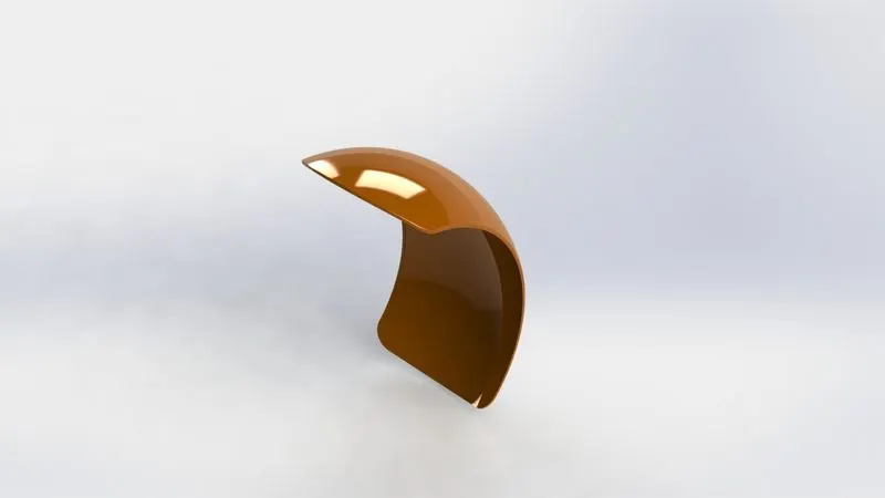
5)REAR FENDER
- Modelling process was similar to that of the front fender
- Additional feature used was Shell feature
- Paint color used-Siena
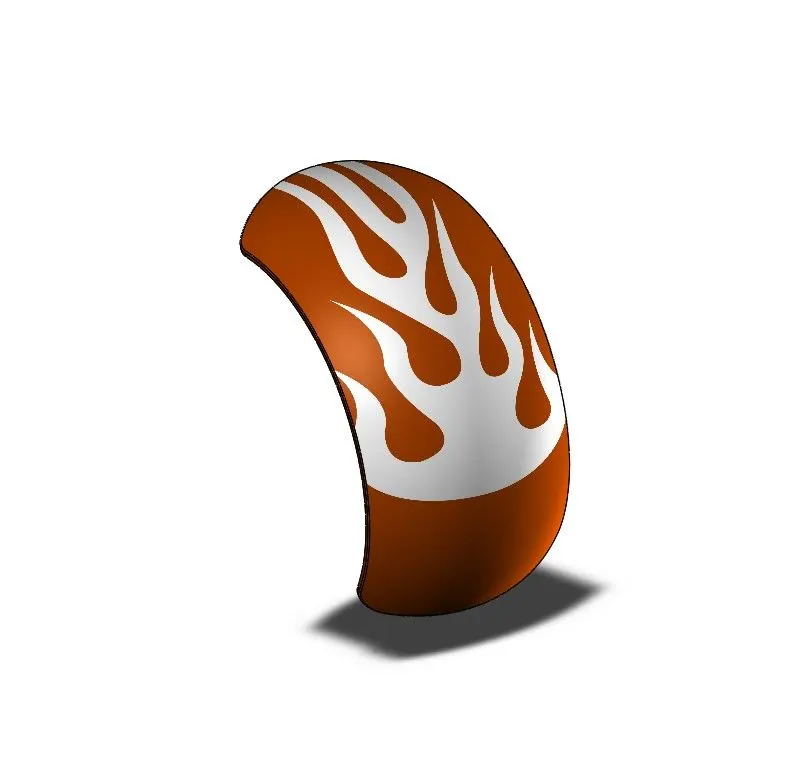
6)FRONT WHEEL
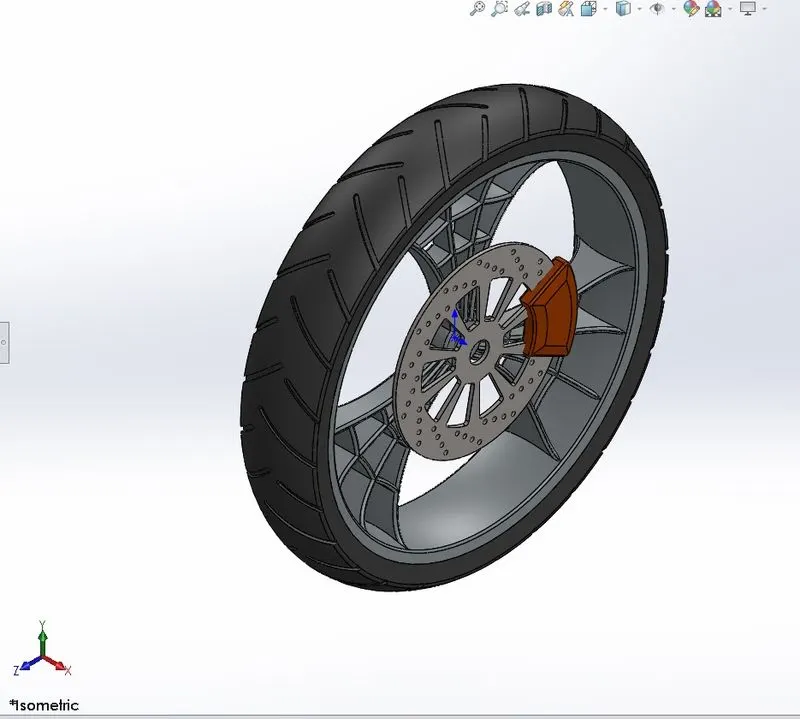
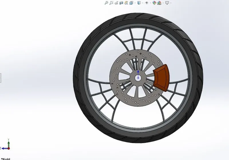
- IT consists of components such as RIM ,DISC BRAKE(ROTOR),TYRE and CALIPER.
- Created a sketch for a single spoke and used circular pattern feature to complete the required amount of spokes
- Used both linear and circular pattern for creating the holes on the rotor
- PAINT USED FOR THE CALIPER-SIENA
- MATERIAL APPLIED FOR SPOKE AND RIM-CHROMIUM PLATE
- FOR TYRE-MATTE RUBBER.
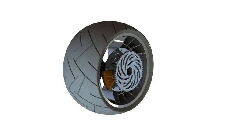
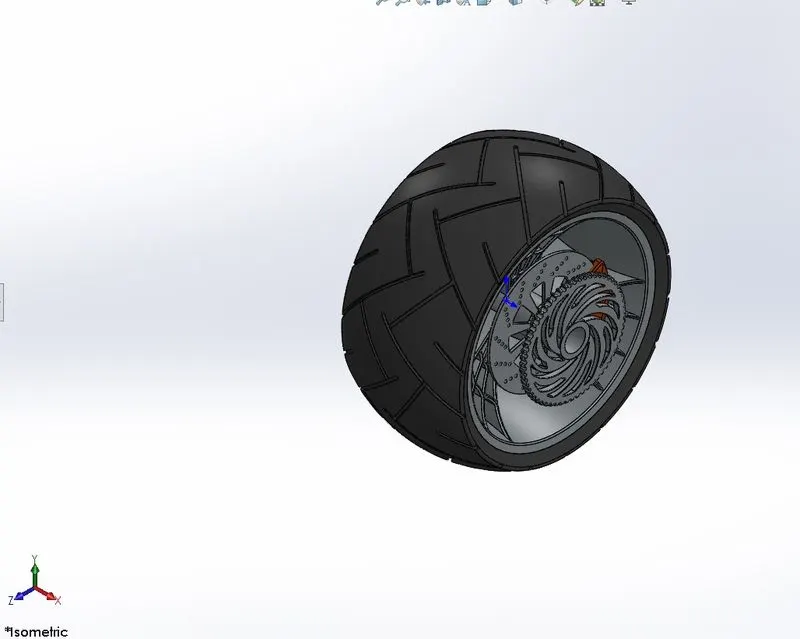
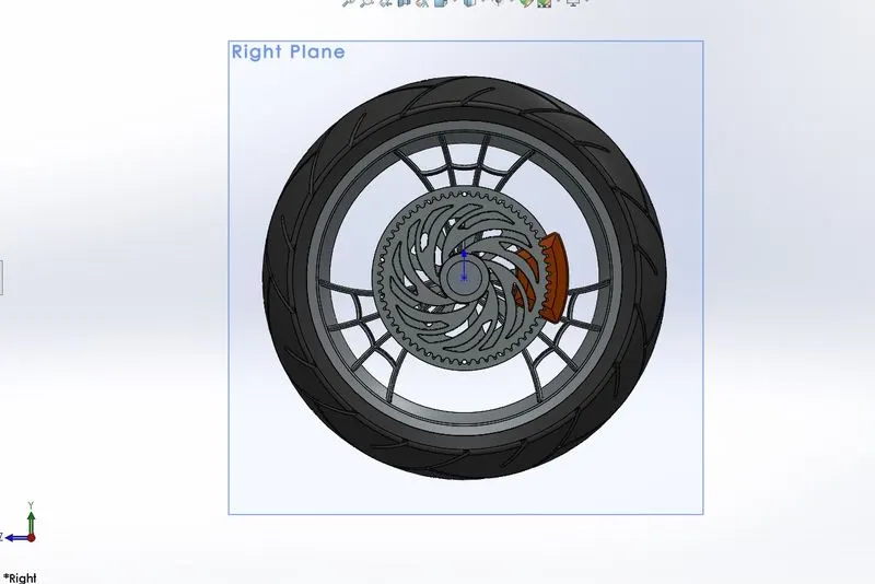
7)REAR WHEEL
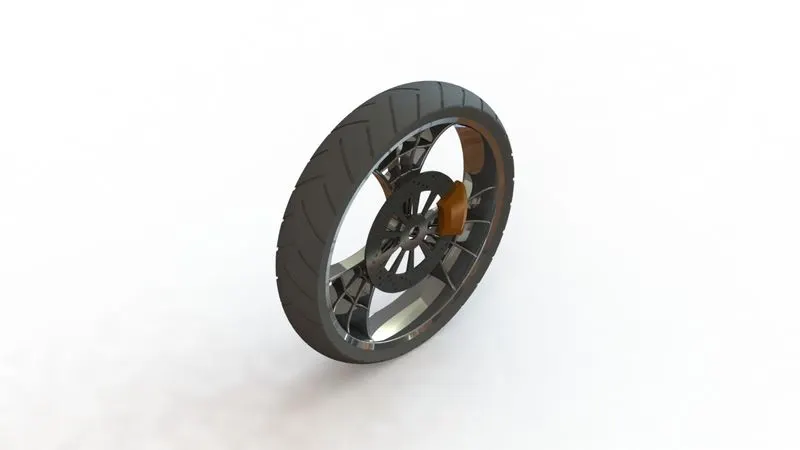
- The process for modelling rear wheel and front wheel are similar.
- The tread pattern design was slightly different for rear wheel
- The total width of the wheel is more compared to the front
- As a result due to more surface area in real time it produces more traction with the road.
- Material applied are same as that of the front wheel.
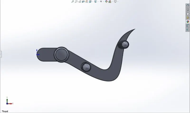
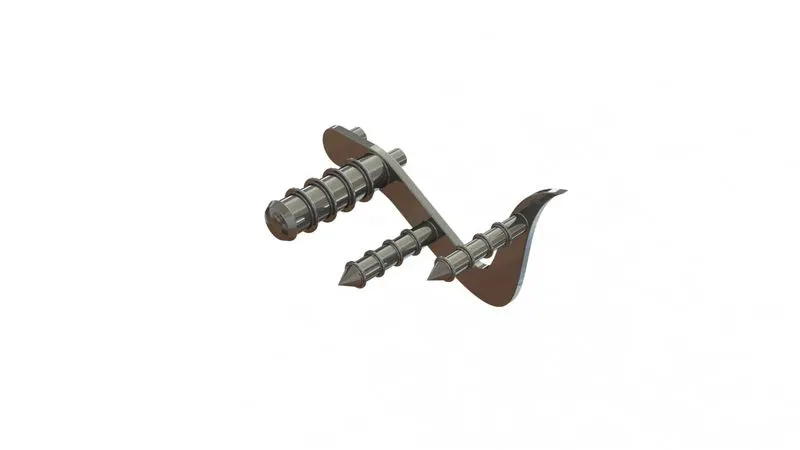
8)PEDAL
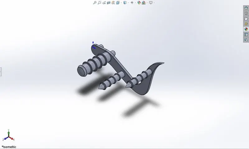
- Got acquainted with chamfer,Linear pattern while modelling the component
- Used mirror bodies option to obtain another pedal of the opposite side
- Material applied-Steel Grey
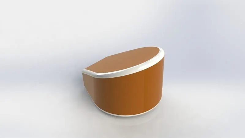
9)OIL TANK
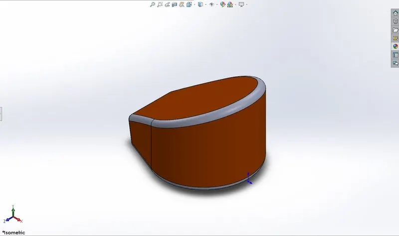
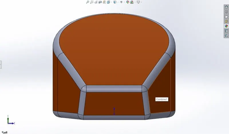
- Extensively used the shell feature to create hollow on the inside.
- Used section view to check out the Shelled feature used on the solid tank.
- Paint color used-Siena
10)FRONT FORK
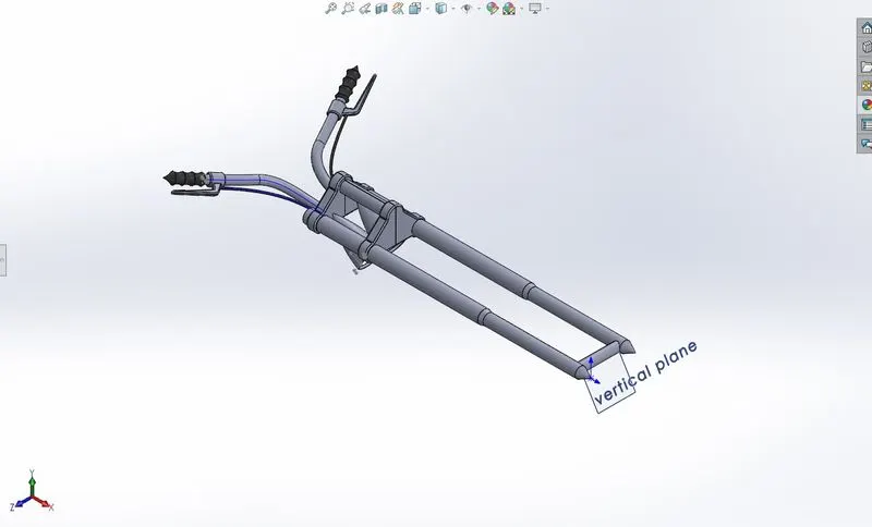
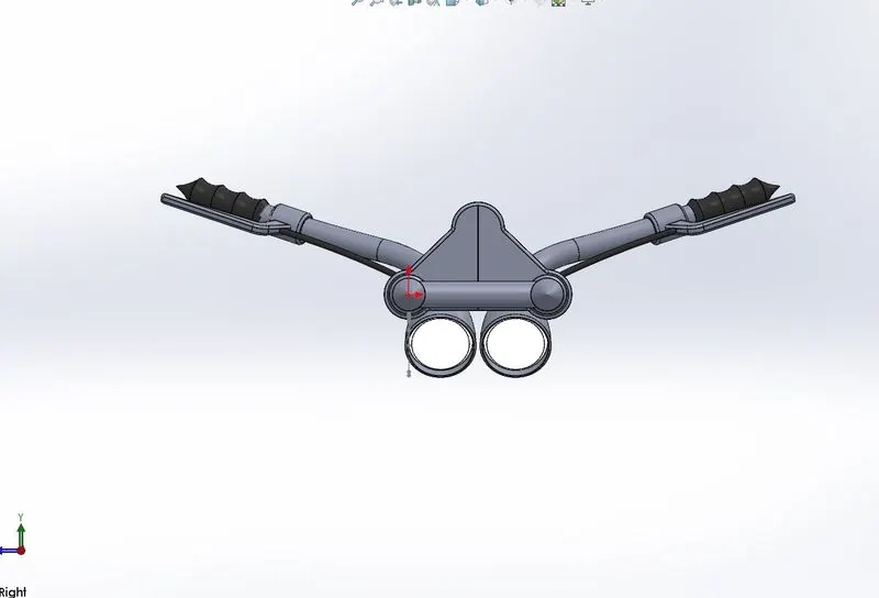
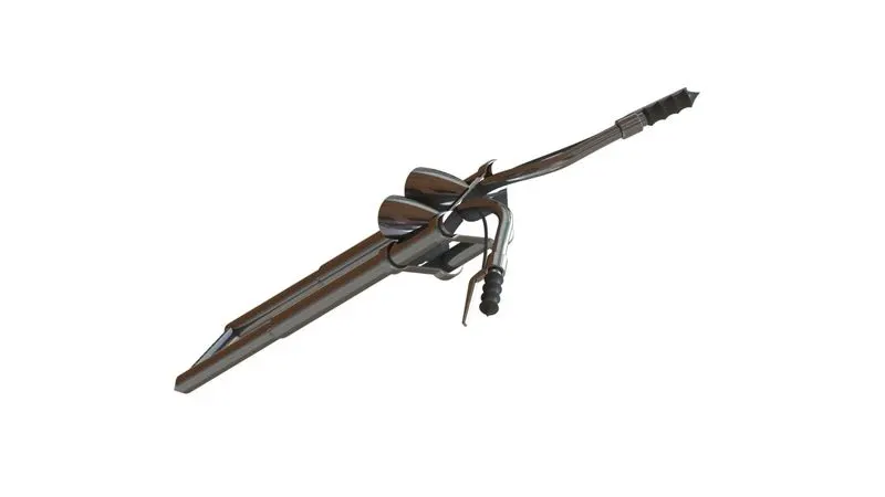
- Used the project curve feature in Solidworks by modelling the handlebars and brake lines fixed in the fork.
- Modelled axle,triple clamps,Hand grips,Brake levers,Brake lines and Handle lamps.
- Material used-Chromium plate.
For brake grips-Matte Black
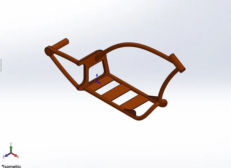
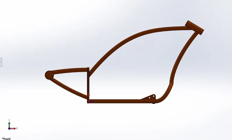
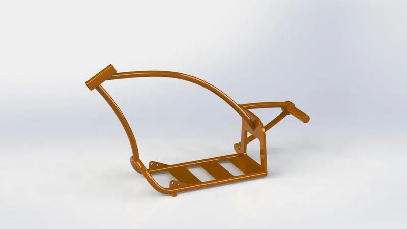
11)CHASSIS
- Chassis is considered as the skeleton of the the whole design.
- The whole model is afixed to the chassis
- Chassis should have suffecient durability and strength to support all its mountings.
- Used projected curve features for creating a number of curves.
- Paint color used-Siena
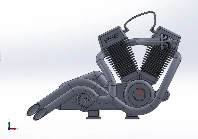
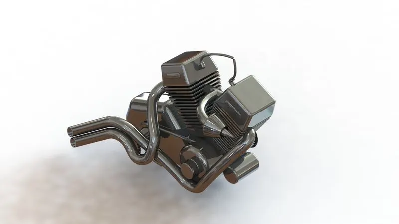
12)ENGINE
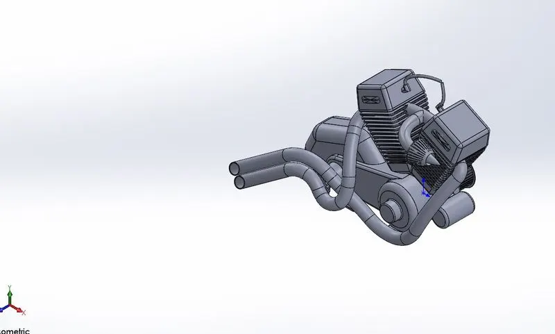
- Here i modeled a V twin(V2) engine for the chopper.
- The cylinders share a common crank shaft and are arranged in a V configuration.
- Gained more insights on the composite curves and pierce features in sketch phase
- Modelled exhaust pipes and Cooling fins as well
- Material applied-Chromium plate
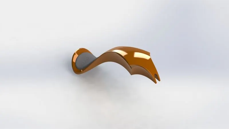
13)GAS TANK
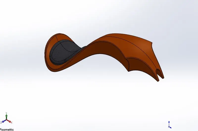
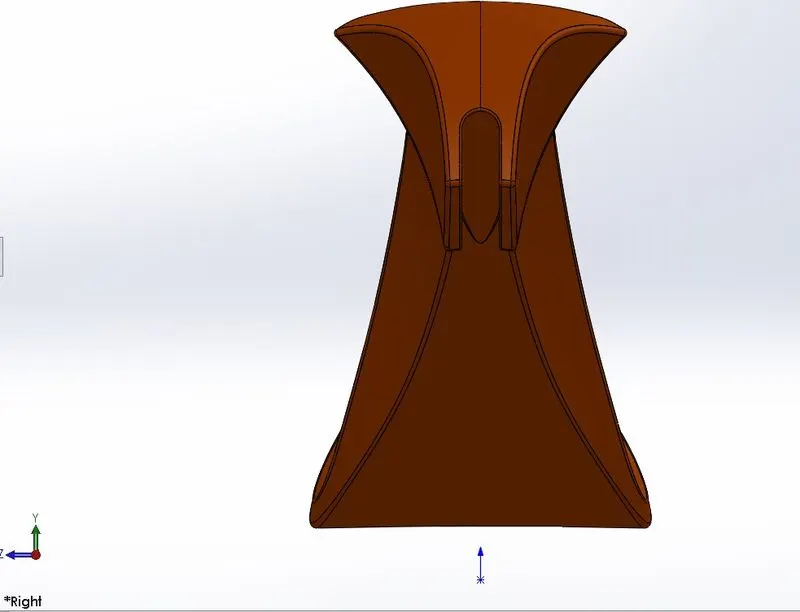
- Here the gas tank and seat are integrated together
- Spline tool is used extensively for making the curve geometry
- Used the knitting tool in the end for integrating both surfaces.
- Paint color used-Siena
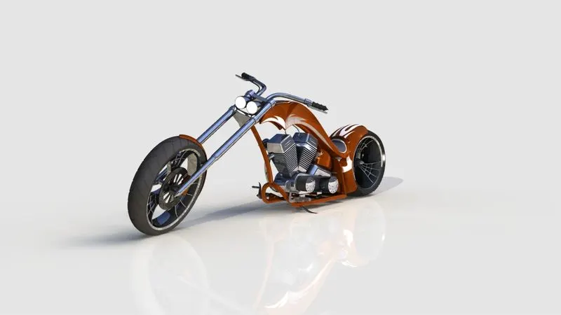
Assembly of Components/Parts i.e The final design
- Used assembly toolbar to insert all the parts in an ordered manner
- Used several different type of mates to snap the different parts in order to produce the final assembly.
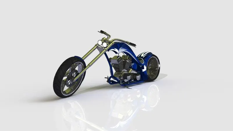
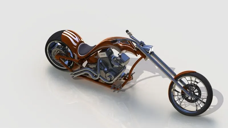
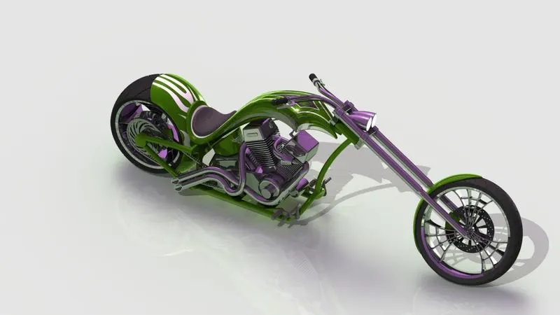
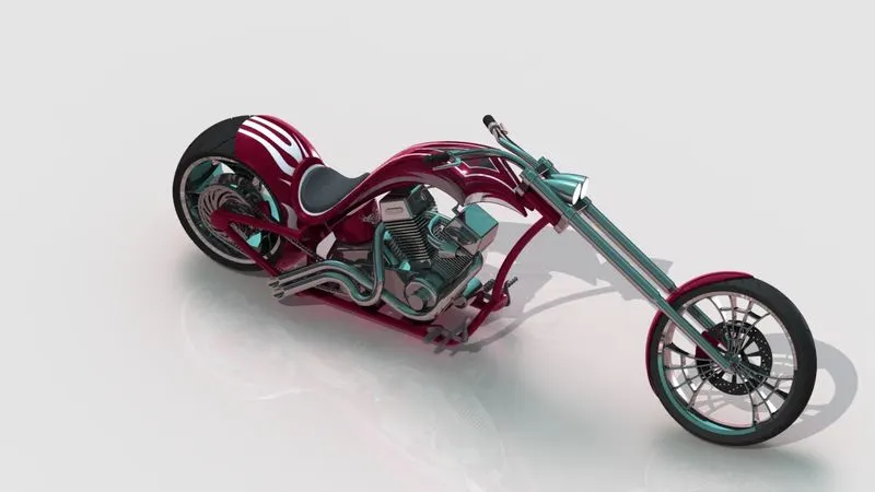
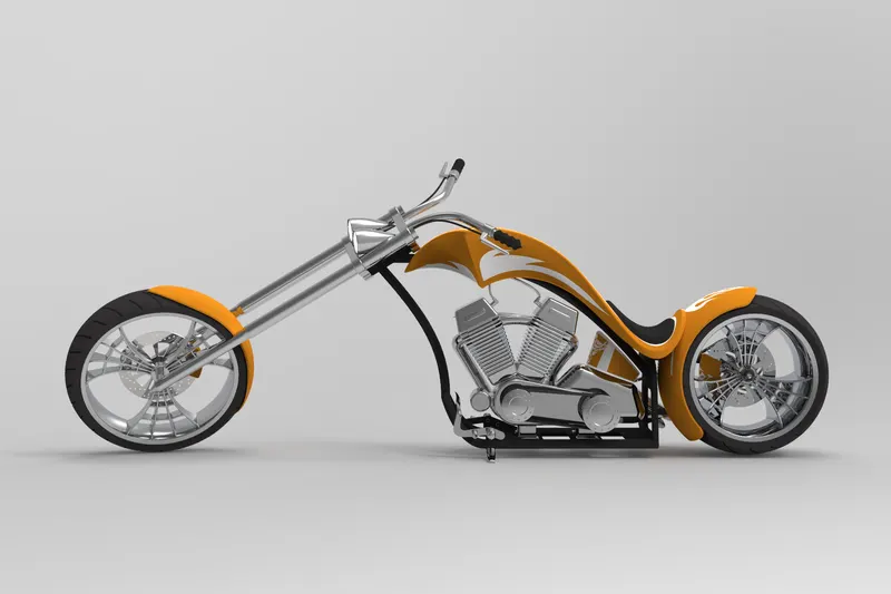
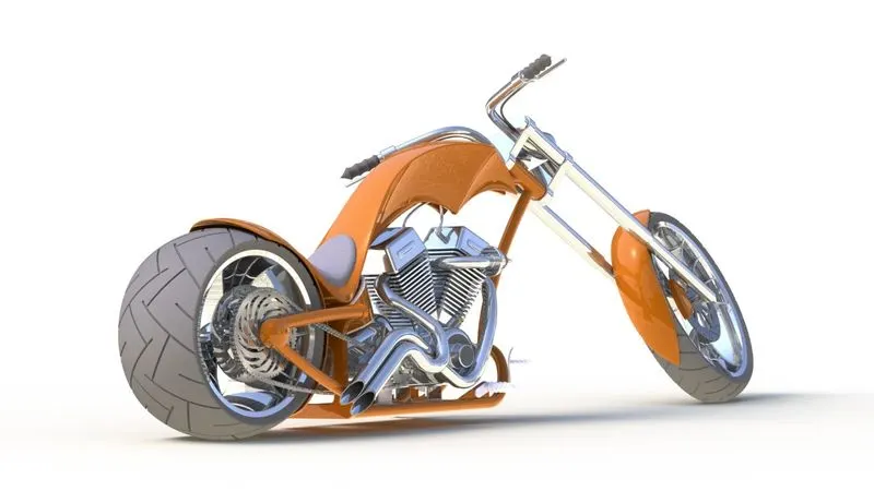
- Used Phooview 360° and solidworks visualize to create several renders shown below
CONCLUSION
All the parts were modelled and assembled to produce the complete 3D design of the AMERICAN CHOPPER and were sucessfully rendered for quality images