MODELLING AND ASSEMBLY OF AMERICAN CHOPPER USING SOLIDWORKS
MODELLING AND ASSEMBLY OF AMERICAN CHOPPER USING SOLIDWORKS
OBJECTIVES:
- To design and model the American chopper.
- To assemble the parts.
- To create a photo realistic rendering of chopper using photoview 360 and visualize.
INTRODUCTION:
The first choppers were built in America. There are many common features between bobbers and choppers, with choppers differentiated being more radically modified, and especially by having the frame tubes and geometry modified to make the bike longer.
The chopper is perhaps the most extreme of all custom styles, often using radically modified steering angles and lengthened forks for a stretched-out appearance. They can be built from an original motorcycle which is modified or built from scratch. Some of the characteristic features of choppers are long front ends with extended forks often coupled with an increased rake angle, lengthened or stretched frames, and larger than stock front wheels.
SOFTWARES USED:
- Solidworks 2018 (photoview 360 add-in)
- Solidworks visualize 2018
DESIGN METHODOLOGY :
SOLIDWORK, a solid modeling computer-aided design and computer-aided engineering program
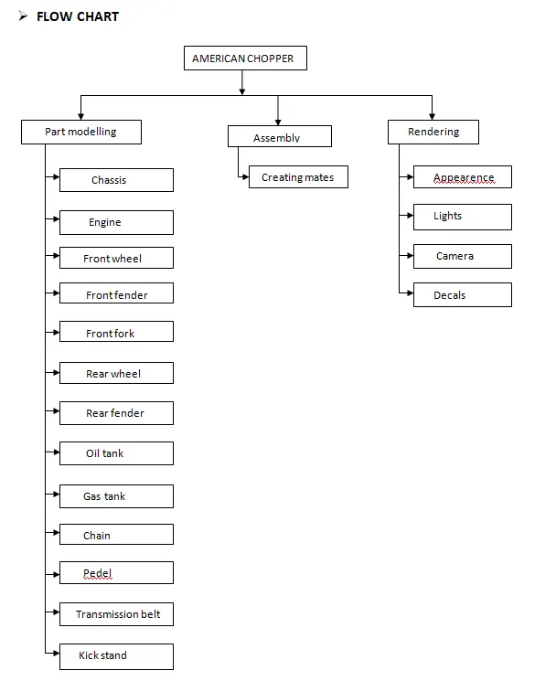
- FLOW CHART
DESCRIPTION:
- COMMANDS USED
- 2D SKETCH
A 2D drawing view consists of two-dimensional elements. It is not associative to a 3D model. A 2D drawing view allows you to quickly create or modify a drawing view without making changes to a part or assembly document.
- 3D SKETCH
A 3D sketch plane is a 2D plane that only exists inside the 3D sketch. When activated, sketching will happen exclusively on that plane and you will get behavior similar to when working in a 2D sketch.
- SPLINE
Spline is a special function defined piecewise by polynomials. Splines are popular curves in these subfields because of the simplicity of their construction, their ease and accuracy of evaluation, and their capacity to approximate complex shapes through curve fitting and interactive curve design.
- SKETCH FILLET
The Sketch Fillet tool trims away the corner at the intersection of two sketch entities to create a tangent arc. This tool is available for both 2D and 3D sketches. The Fillet tool on the Features toolbar fillets entities such as edges in parts.
- ELLIPSE
The ellipse tool to create a complete ellipse. Use the partial ellipse tool to create an elliptical arc.
- FILLETS
Fillet/Round creates a rounded internal or external face on the part. you can fillet all edges of a faces, selected sets of faces, selected edegs or selected loops.
- BOSS EXTRUDE
Creates a solid base on the sketch.
- CUT EXTRUDE
Makes a cut out of the existing body.
- REVOLVE BOSS
This feature is used to revolve a 2D sketch along an Axis or Centerline.
- REVOLVE CUT
Revolved cut removes materials by revolving a closed profile a along an axis.
- SWEEP
Sweep is the one feature in Solidworks that helps sweep a closed profile along a closed or open path.
- LOFT
The loft feature in solidworks allows you generate complex geometry in a single feature. It does this by interpolating surfaces between various cross-sections of a model. These cross-sections can be sketches, faces, or edges. In the loft interface, these cross-sections are considered “Loft Profiles”.
- CHAMFER
The chamfer tool creates a beveled feature on selected edges, faces, or a vertex. Set the Distance and Angle in the Chamfer PropertyManager or in the graphics area. A manipulator arrow appears that points in the direction in which the distance is measured.
- SHELL
The shell tool hollows out a part, leaves open the faces you select, and creates thin-walled features on the remaining faces. If you do not select any face on the model, you can shell a solid part, creating a closed, hollow model. You can also shell a model using multiple thicknesses.
- DOME
The software calculates the distance using the radius of the arc as a basis for the dome. It creates a dome that is tangent to the adjacent cylindrical or conical face.
- LINEAR PATTERN
Use linear patterns to create multiple instances of one or more features that you can space uniformly along one or two linear paths.
- CIRCULAR PATTERN
Use circular patterns to create multiple instances of one or more features that you can space uniformly around an axis. Pattern instances inherit the feature color of the original feature when the Pattern is based on one feature.
- SKETCH DRIVEN PATTERN
Using sketch points within a sketch, you can specify a feature pattern. The seed feature propagates throughout the pattern to each point in the sketch. You can use sketch driven patterns for holes or other feature instances.
- SPLIT
The SOLIDWORKS Split Line tool is used to project an entity (sketch, solid, surface, face, plane, or surface spline) onto other surfaces or curved/planar faces. You are also able to split faces on multiple bodies with one command.
- PROJECTED CURVE
It is a tool you are going to use to form 3D curves from two 2D curves from two different planes
- EXTEND
You can add to the length of a sketch entity (line, centerline, or arc). Use Extend Entities to extend a sketch entity to meet another sketch entity.
- CONVERT ENTITIES
The Convert Entities tool allows users to make a copied projection of a given sketch, face, or set of edges onto the active sketch plane. These sketch entities will update their size and/or positioning if either of these characteristics changes in the source sketch.
- TRIM
You can use Power trim to trim multiple, adjacent sketch entities by dragging the pointer across each sketch entity. To trim with the Power trim option: Right-click the sketch and select Edit Sketch. Continue to hold down the pointer and drag across each sketch entity you want to trim.
- MIRROR
Creates a copy of a feature, (or multiple features), mirrored about a face or a plane. You can select the feature or you can select the faces that comprise the feature. Bodies to Mirror. Select a body in a single model or multibody part to create a mirror entity.
- SKETCH PICTURE
To insert and resize a picture on a sketch plane: In an open sketch, click Sketch Picture. (Sketch toolbar) or click Tools > Sketch Tools > Sketch Picture. In the dialog box, browse to the picture file and click Open. When you insert a picture, the scale tool automatically displays.
- SKETCH PATTERN
Using sketch points within a sketch, you can specify a feature pattern. The seed feature propagates throughout the pattern to each point in the sketch. You can use sketch driven patterns for holes or other feature instances.
- DYNAMIC MIRROR SKETCH ENTITIES
This tool allows the user to mirror a sketch about a line while the user is creating their sketch. Depending on design intent this tool can save an immense amount of time.
DESIGN AND MODELLING:
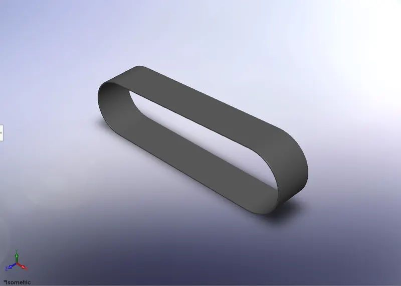
- TRANSMISSION BELT
Transmission belt is a loop os flexible material used to link the two rotating shafts mechanically.
Commands used: SKETCH, EXTRUDE BOSS, OFFSET ENTITIES, FILLETS
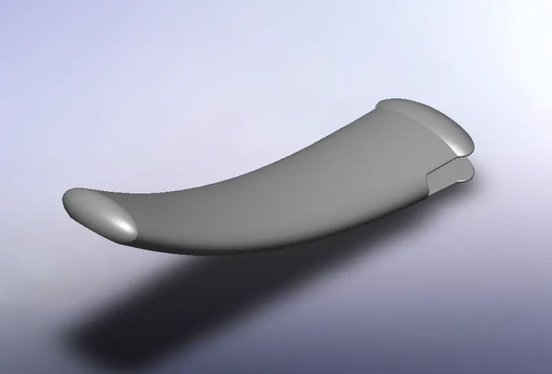
- KICKSTAND
Kickstand is used to support the vehicle by keeping it upright.
Commands used : SKETCH, LOFTED BOSS, DOME, EXTRUDED CUT, SPLIT BODY, EXTUDED BOSS, FILLET.
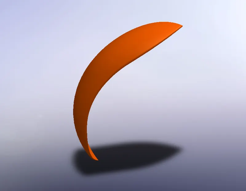
- FRONT FENDER
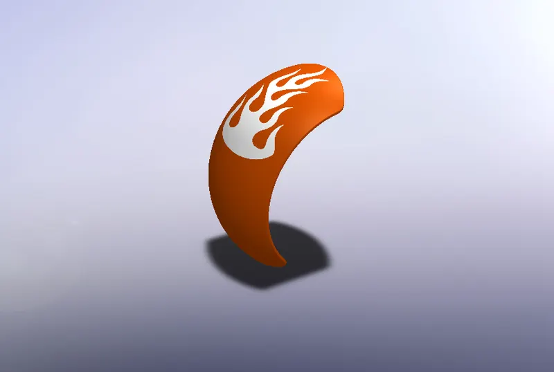
Fender is a body that frames the wheel well. It primary purpose is to prevent sand, mud, rocks, and road spray, from being thrown into air by the rotating tyre.
Commands used : Sketch, Offset entities, Revolved Boss, Split body, Fillet.
- REAR FENDER
Fender is a body that frames the wheel well. It primary purpose is to prevent sand, mud, rocks, and road spray, from being thrown into air by the rotating tyre.
Commands used : Sketch, offset entities, Revolved boss, Split body, Fillet, Shell.
- OIL TANK
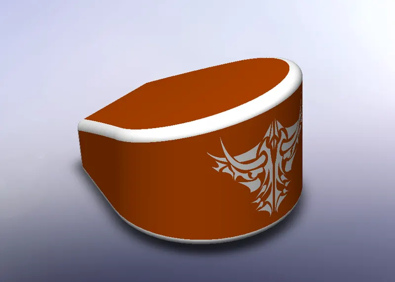
Stores the oil for lubrication and cooling purpose.
Commands used : Sketch , Extrude boss, Combine, Fillet, Shell.
- CHAIN
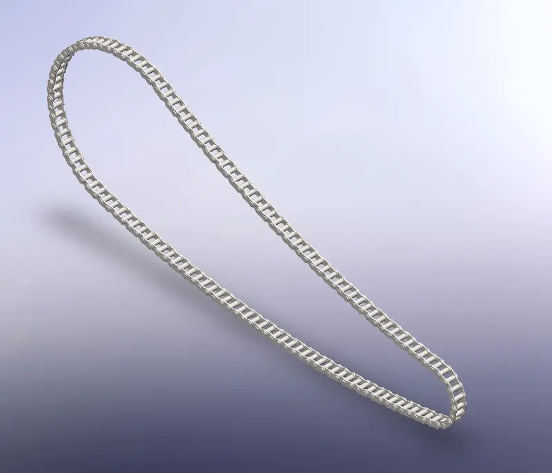
Chain drive is used for transmission of mechanical power, in this case the power from the engine to the wheels of the vehicle.
Commands used : Sketch, MAKE BLOCKS, Extruded boss, Fillet, CURVE DRIVEN PATTREN, MIRROR.
- PEDEL
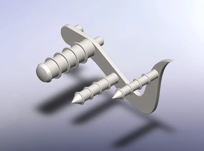
Used for placing the foot, applying the brakes and shifting the gear in a motorcycle.
Commands used : Sketch, Extruded boss, Fillet, Revolved boss, Dome, Chamfer, Linear pattern.
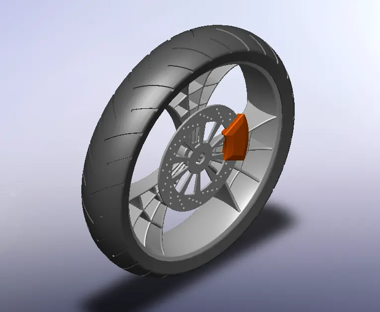
- FRONT WHEEL
The front wheel consists of unique spider web shaped rims, tyre, break and calliper.
Commands used : Sketch, Offset entities, Convert Entities, Trim Entities, Revolved boss, Extrude boss, Extrude cut, Revolved cut, Circular pattern, Combine, Fillet, Chamfer.
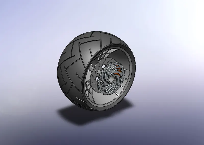
- REAR WHEEL
The wider but stoker rear wheel consists of the unique spider web shaped rim , tyre, brake rotor, calliper and sprocket.
Commands used : Sketch, Offset entities, Convert entities, Trim entities, Revolved boss, Extrude boss, Extrude cut, Revolved cut, Circular pattern . Combine, Fillet, Chamfer.
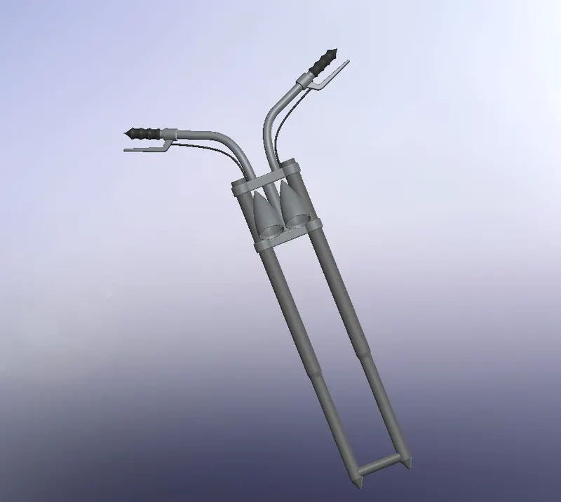
- FRONT FORK
The fork connets the front wheels and axle to its frame by a triple clamp which consists of a upper yoke join the lower yoke via a steering stem, the shaft that runs through the steering head, crating the steering axis.
Commands used : Sketch, Revolved boss, Extrude boss, Fillet, Linear pattern, Extrude cut, Dome, Revolved cut, Move/copy body, Project curve, Swept boss, Mirror, Combine.
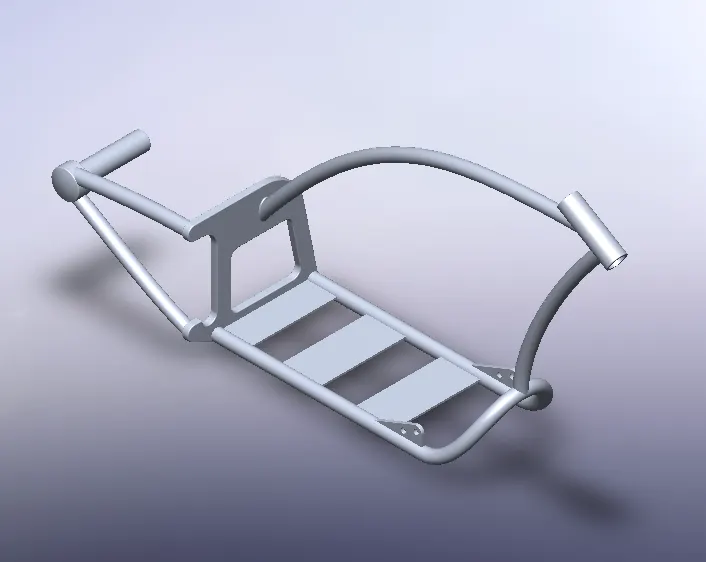
- CHASSIS
Chassis is the motorcycles core structure. It supports the engine , provides a location for the steering and supports the rear end and the rider with any passenger or luggage. The fuel thank is attached to the frame.
Commands used : Sketch, Convert entities, Project curve, Swept boss, Mirror, Extrude boss, Extrude cut, Chamfer, Fillet, Dome, Split body, Combine.
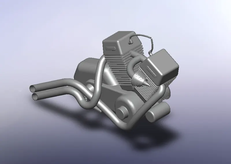
- ENGINE
An engine powers a motorcycle, her a v type engine also called v2 engine is used. It is a two cylinder piston engine where the two cylinders share a common crankshaft and are arranged in a v configuration. The v configuration generally reduces the overall engine length, hight and weight compared with the same in line configuration.
Commands used : Sketch, Convert entities, Extrude boss, Revolved boss, Fillet, Circular pattern, Dome, Extrude cut, Chamfer, Linear pattern, Mirror, Split body, Swept boss, Combine, Project curve, Composite curve.
- GAS TANK
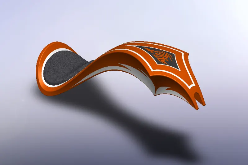
Ulike the other parts where the solid modelling was used, gas tank was majorly designed using surface modelling.
Commands used : Sketch, Convert entities, Swept surface, Trime surface, Project curve, Lofted surface, Boundary surface, Mirror, Knift surface, Slit line, Extrude surface, Fillet, Swept cut, Shell.
ASSEMBLY :
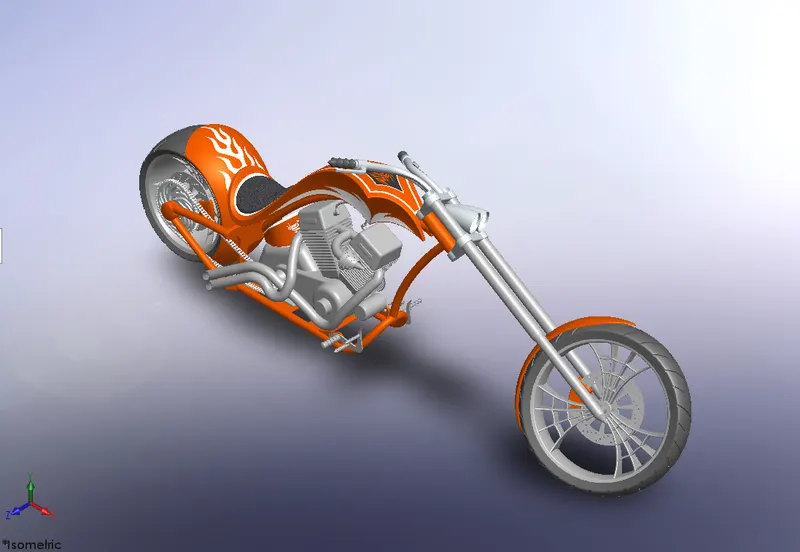
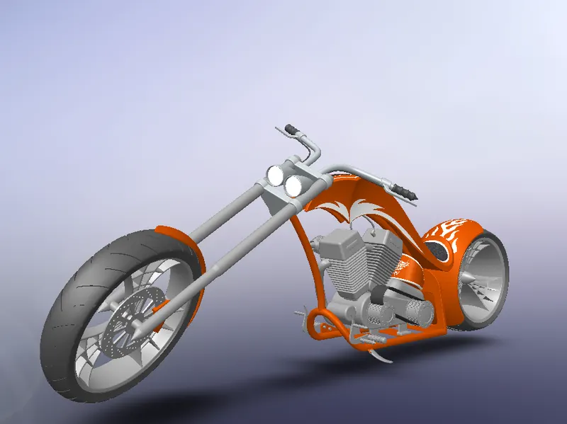
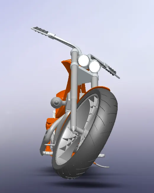
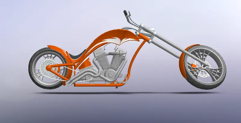
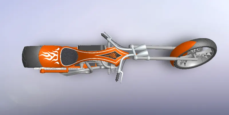
Assembeld the parts of chopper using Standard mates (Coincident, Paraller, Tangent, Perpendicular etc ), Advanced mates (Symmetry, Width, Angle Etc) and Mirroring.
Some parts like Kickstand and Front fork needed a limiting angle which was set while applying the mates. Some parts had to be edited to avoid any bad geometry for showing up in the assembly.
- ISOMETRIC VIEW
- CAMERA VIEW
- FRONT VIEW
- SIDE VIEW
- TOP VIEW
RENDERING :
Rendering the model was done using the Photoview 360 and Solidworks visualize.
Decals where applied in the case of oil tank, gas tank, front fender and rear fender.
- PHOTOVIEW 360
Rendering using photoview 360 involved setting the Scene, Environmment, camera, Perspective and Lights by adjusting various parameters. Extra mates where added to give more realistic views of the scene.
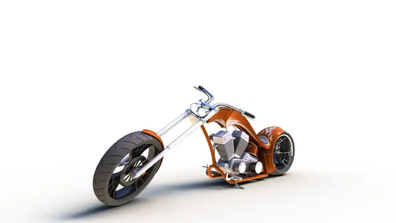
- SOLIDWORKS VISUALIZE
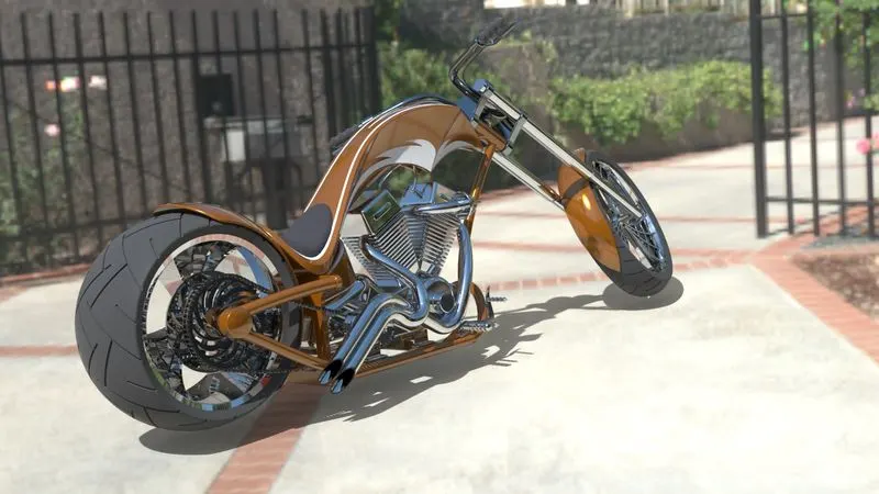
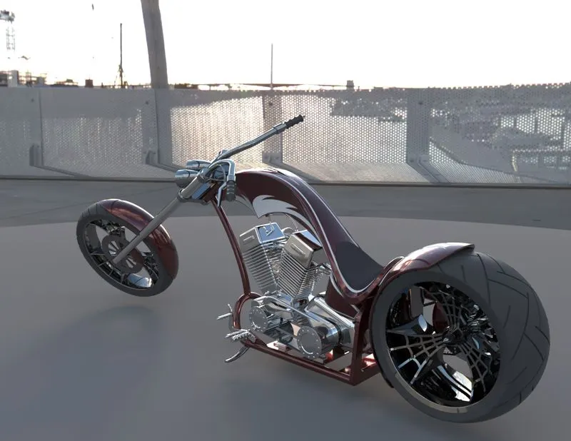
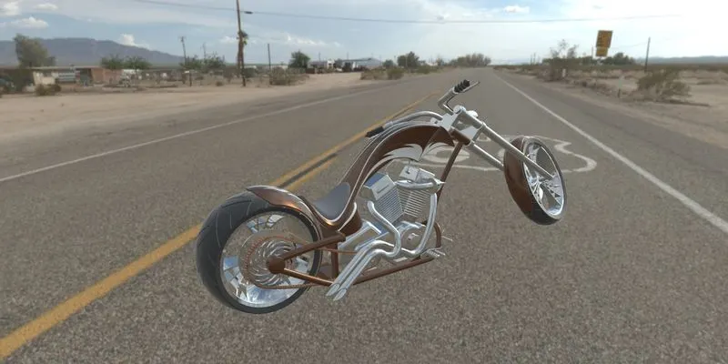
The assembly was imported to solidworks visualize and various adjustments of colour were done incase of multiple rendering. The Environment, Backplate and Camera position were choosen and tweated accordingly to give the image a photorealistic image
- SUNNY DRIVE WAY
- DOCKLANDS BRIDGE
- ROUTE 66
CONCLUSION:
Thus the exterior parts of an american chopper were designed, modelled and assembeld using solidworks 2018 and photorealistically rendered using solidworks visualize 2018.