MODELLING AND ASSEMBLY OF SUNSEEKER PREDATOR YACHT USING SOLIDWORKS
MODELLING AND ASSEMBLY OF SUNSEEKER PREDATOR YACHT USING SOLIDWORKS
OBJECTIVES:
- To design and model the Predator yacht.
- To create the parts using surface modelling.
- To assemble the parts.
- To create a photo realistic rendering of yacht using photoview 360 and visualize.
INTRODUCTION:
The term, yacht, originates from the Dutch word jacht , and originally referred to light, fast sailing vessels that the dutch republic navy used to pursue pirates and other transgressors around and into the shallow waters of the low countries.
A yacht is a sail or power vessel used for pleasure, cruising, or racing. Originally, all yachts were made of wood, using a wooden keel and ribs, clad with planks. These materials were supplanted with iron or steel in steam yachts. In the 1960s fiberglass became a prevalent material. These materials and others continue in use. Whereas yachts of 79 feet (24 m) and below may be constructed of fiber glass larger yachts are more likely to be constructed of steel, aluminum or composite fiber reinforced plastic.
High-performance rigs provide aerodynamic efficiency and hydrodynamically efficient hulls minimize drag through the water and sideways motion.
SOFTWARES USED:
- Solidworks 2018 (photoview 360 add-in)
- Solidworks visualize 2018
DESIGN METHODOLOGY :
SOLIDWORK a solid modeling computer-aided design and computer-aided engineering program. Surface modeling is a more complex method for representing objects than wireframe modeling, but not as sophisticated as solid modeling. Surface modeling is widely used in CAD (computer-aided design) for illustrations and architectural renderings. It is also used in 3D animation for games and other presentations.
Although surface and solid models appear the same on screen, they are quite different. Surface models cannot be sliced open as can solid models. In addition, in surface modeling, the object can be geometrically incorrect; whereas, in solid modeling, it must be correct
- FLOW CHART
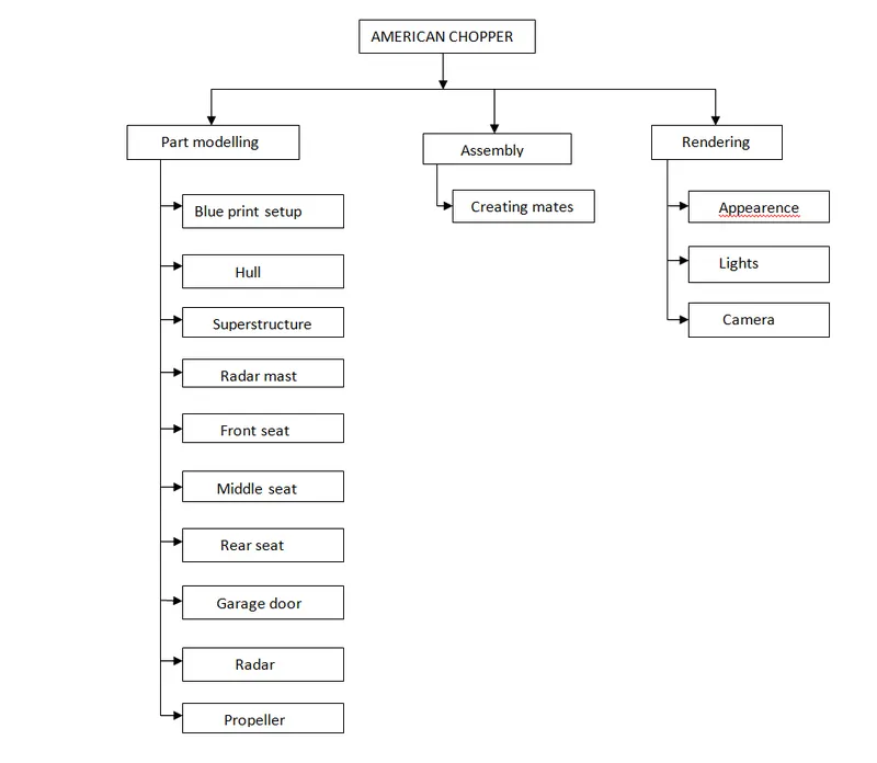
DESCRIPTION:
- COMMANDS USED
- 2D SKETCH
A 2D drawing view consists of two-dimensional elements. It is not associative to a 3D model. A 2D drawing view allows you to quickly create or modify a drawing view without making changes to a part or assembly document.
- 3D SKETCH
A 3D sketch plane is a 2D plane that only exists inside the 3D sketch. When activated, sketching will happen exclusively on that plane and you will get behavior similar to when working in a 2D sketch.
- SPLINE
Spline is a special function defined piecewise by polynomials. Splines are popular curves in these subfields because of the simplicity of their construction, their ease and accuracy of evaluation, and their capacity to approximate complex shapes through curve fitting and interactive curve design.
- SKETCH FILLET
The Sketch Fillet tool trims away the corner at the intersection of two sketch entities to create a tangent arc. This tool is available for both 2D and 3D sketches. The Fillet tool on the Features toolbar fillets entities such as edges in parts.
- FILLETS
Fillet/Round creates a rounded internal or external face on the part. you can fillet all edges of a faces, selected sets of faces, selected edegs or selected loops.
- BOSS EXTRUDE
Creates a solid base on the sketch.
- CUT EXTRUDE
Makes a cut out of the existing body.
- REVOLVE BOSS
This feature is used to revolve a 2D sketch along an Axis or Centerline.
- REVOLVE CUT
Revolved cut removes materials by revolving a closed profile a along an axis.
- SWEEP
Sweep is the one feature in Solidworks that helps sweep a closed profile along a closed or open path.
- LOFT
The loft feature in solidworks allows you generate complex geometry in a single feature. It does this by interpolating surfaces between various cross-sections of a model. These cross-sections can be sketches, faces, or edges. In the loft interface, these cross-sections are considered “Loft Profiles”.
- CHAMFER
The chamfer tool creates a beveled feature on selected edges, faces, or a vertex. Set the Distance and Angle in the Chamfer PropertyManager or in the graphics area. A manipulator arrow appears that points in the direction in which the distance is measured.
- SHELL
The shell tool hollows out a part, leaves open the faces you select, and creates thin-walled features on the remaining faces. If you do not select any face on the model, you can shell a solid part, creating a closed, hollow model. You can also shell a model using multiple thicknesses.
- DOME
The software calculates the distance using the radius of the arc as a basis for the dome. It creates a dome that is tangent to the adjacent cylindrical or conical face.
- LINEAR PATTERN
Use linear patterns to create multiple instances of one or more features that you can space uniformly along one or two linear paths.
- CIRCULAR PATTERN
Use circular patterns to create multiple instances of one or more features that you can space uniformly around an axis. Pattern instances inherit the feature color of the original feature when the Pattern is based on one feature.
- SKETCH DRIVEN PATTERN
Using sketch points within a sketch, you can specify a feature pattern. The seed feature propagates throughout the pattern to each point in the sketch. You can use sketch driven patterns for holes or other feature instances.
- SPLIT
The SOLIDWORKS Split Line tool is used to project an entity (sketch, solid, surface, face, plane, or surface spline) onto other surfaces or curved/planar faces. You are also able to split faces on multiple bodies with one command.
- PROJECTED CURVE
It is a tool you are going to use to form 3D curves from two 2D curves from two different planes
- EXTEND
You can add to the length of a sketch entity (line, centerline, or arc). Use Extend Entities to extend a sketch entity to meet another sketch entity.
- CONVERT ENTITIES
The Convert Entities tool allows users to make a copied projection of a given sketch, face, or set of edges onto the active sketch plane. These sketch entities will update their size and/or positioning if either of these characteristics changes in the source sketch.
- TRIM
You can use Power trim to trim multiple, adjacent sketch entities by dragging the pointer across each sketch entity. To trim with the Power trim option: Right-click the sketch and select Edit Sketch. Continue to hold down the pointer and drag across each sketch entity you want to trim.
- MIRROR
Creates a copy of a feature, (or multiple features), mirrored about a face or a plane. You can select the feature or you can select the faces that comprise the feature. Bodies to Mirror. Select a body in a single model or multibody part to create a mirror entity.
- SKETCH PICTURE
To insert and resize a picture on a sketch plane: In an open sketch, click Sketch Picture. (Sketch toolbar) or click Tools > Sketch Tools > Sketch Picture. In the dialog box, browse to the picture file and click Open. When you insert a picture, the scale tool automatically displays.
- SKETCH PATTERN
Using sketch points within a sketch, you can specify a feature pattern. The seed feature propagates throughout the pattern to each point in the sketch. You can use sketch driven patterns for holes or other feature instances.
- DYNAMIC MIRROR SKETCH ENTITIES
This tool allows the user to mirror a sketch about a line while the user is creating their sketch. Depending on design intent this tool can save an immense amount of time.
- SURFACE LOFT
It connects two sketch profiles to make a surface and it can be guided by several number of curves.
- SURFACE EXTRUDE
It is just like protrysion of something out of a plane. It can be drawn as a single line or a closed sketch entity to make it a surface extrusion.
- BOUNDARY SURFACE
Boundary surface creates a surface covering up the provided boundaries by sketch profile.
- SURFACE FILL
It fills up the closed space created by selected either the sketch entities or curves or any edges of existing surfaces or features.
- SURFACE TRIM
You can use a surface, plane, or sketch as a trim tool to trim intersecting surfaces.
- SURFACE KNIT
Use the Knit Surface tool to combine two or more faces and surfaces into one. Knit surfaces absorb the surface bodies you used to create them.Create a solid body when the knit surfaces form a closed volume, or leave as a surface body. Select Merge entities to merge faces with the same underlying geometry.
DESIGN AND MODELLING:
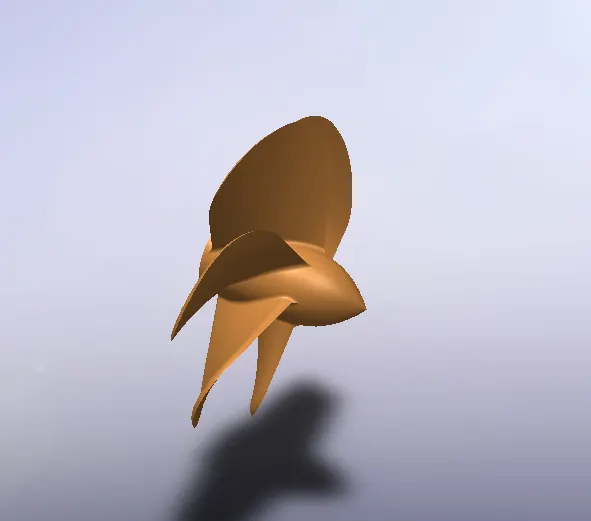
- PROPELLER
A propeller is a device with a rotating hub and radiating blades that are set at a pitch to form a helical spiral, that, when rotated, performs an action which is similar to Archemedie's principal. It transforms rotational power into linear thrust by acting upon a working fluid, such as water or air. The rotational motion of the blades is converted into thrust by creating a pressure difference between the two surfaces Most marine propellers are screw propellers with helical blades rotating on a propeller shaft with an approximately horizontal axis.
Commands used: SKETCH, REVOLVED BOSS , LOFTED BOSS, FILLETS, EXTRUDE CUT , CIRCULAR PATTREN.
- RADAR
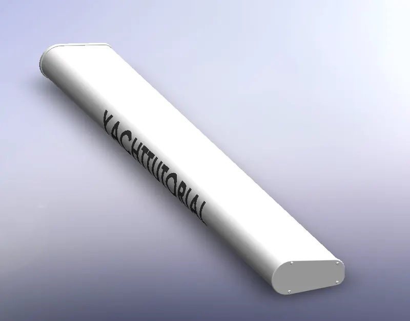
Radar is a detection system that uses radio waves to determine the range, angle, or velocity of objects. It can be used to detect aircraft, ships. A radar system consists of a transmitter producing electromagnetic wavesin the radio or micro wave domain, a transmitting antenna, a receiving antenna and a receiver and proccesor to determine properties of the object. Radio waves from the transmitter reflect off the object and return to the receiver, giving information about the object's location and speed.
Commands used : SKETCH, OFF SET ENTITIES, CONVERT ENTITIES,EXTRUDED BOSS, SKETCH DRIVEN PATTREN, MIRROR, SPLIT LINE ,EXTRUDED CUT, FILLET.
- BLUE PRINT SETUP
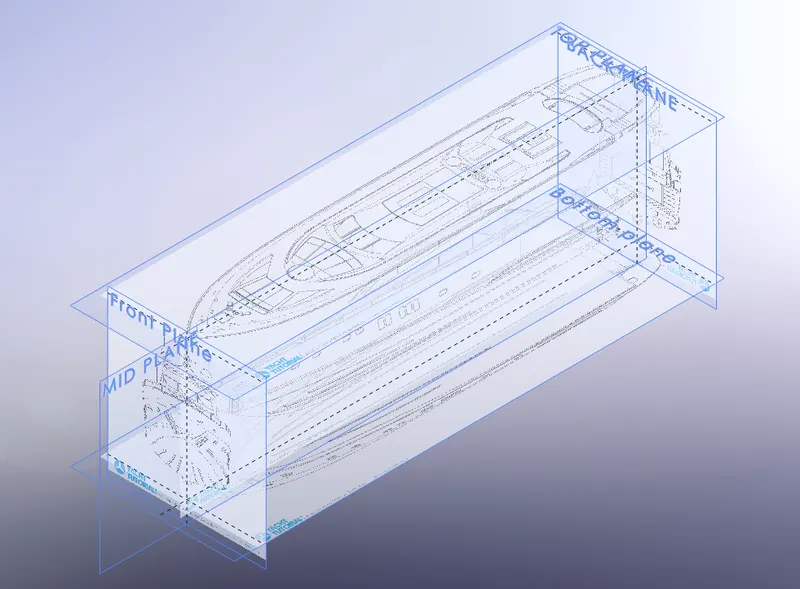
A blueprint is a reproduction of a technical drawing and engineering drawing using a contact print process on light-sensitive sheets. The blueprint process was characterized by white lines on a blue background, a negative of the original.
Commands used : SKETCH PICTURES.
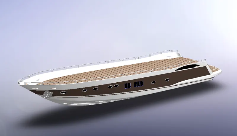
- HULL
A hull is the watertight body of a ship or boat. The hull may open at the top , or it may be fully or partially covered with a deck. Atop the deck may be a deckhouse and other superstructure such as a funnel, derrick, or mast. The line where the hull meets the water surface is called the waterline.
There is a wide variety of hull types that are chosen for suitability for different usages, the hull shape being dependent upon the needs of the design. Shapes range from a nearly perfect box in the case of scow barges to a needle-sharp surface of revolution in the case of a racing multihull sailboat.
Commands used : Sketch, offset entities, Project curve, Lofted surface, Trim surface, Extruded surface, Kint surface, Filled surface, Shell, Chamfer, Swept boss, Dome, Helix/ spiral, Linear pattern, Delet face, 3D sketch, Slit body, Offset surface,Extruded boss, Extruded cut, Fillet, Revolved boss, Mirror, Split line .
- SUPERSTRUCTURE
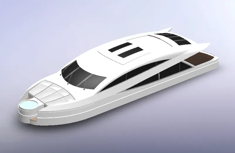
A superstructure is an upward extension of an existing structure above a baseline. This term is applied to various kinds of physical structures such as ships having the degree of freedom zero As stated above, superstructure consists of the parts of the ship or a boat including sailboats, fishingboats and submarain that project above her main deck. This does not usually include its masts.
The height and the weight of superstructure on board a ship or a boat also affects the amount of freeboard that such a vessel requires along its sides, down to her waterline. In broad terms, the more and heavier superstructure that a ship possesses (as a fraction of her length), the less the freeboard that is needed.
Commands used : Sketch , offset entities,Convert entities, Project curve, Lofted surface, Trim surface, Extruded surface, Kint surface, Filled surface, Shell, Chamfer, Swept boss, Dome, Helix/ spiral, Linear pattern, Delet face, 3D sketch, Slit body, Offset surface,Extruded boss, Extruded cut, Fillet, Revolved boss, Mirror, Split line,Thicken surface .
- GARAGE DOOR
A garage door is a large door on a garage that opens either manually or by an electric motor. Garage doors are frequently large enough to accommodate automobileand other vehicles. Small garage doors may be made in a single panel that tilts up and back across the garage ceiling. Larger doors are usually made in several jointed panels that roll up on tracks across the garage ceiling, or into a roll above the doorway.
The operating mechanism is spring-loaded or counterbalanced to offset the weight of the door and reduce human or motor effort required to operate the door.
Commands used : Sketch, , Extrud cut, Shell ,Fillet, Mirror.
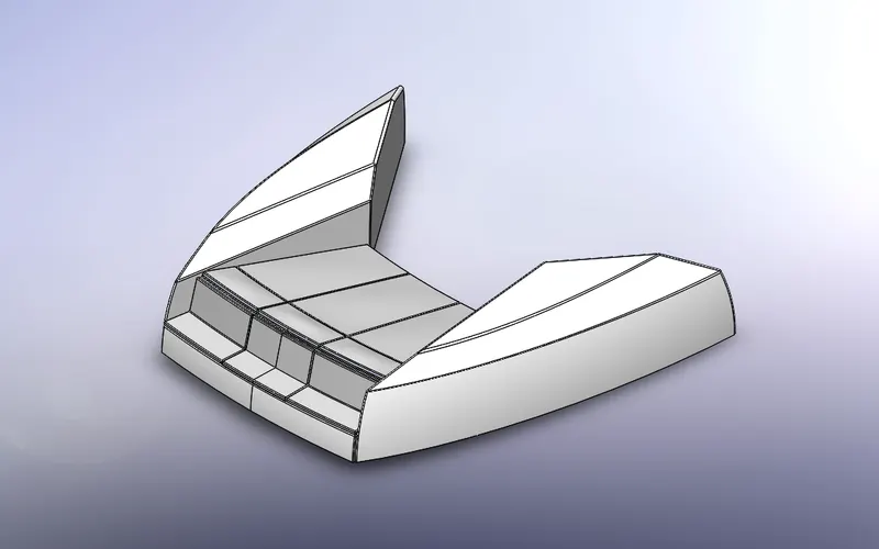
- FRONT SEAT
The front seat was placed infrom of the superstructure on the hull. It was designed after importing the deck surface of the hull as interface surface.
Commands used : Sketch, Offset entities,Swept surface,Extrude surface, Trim surface, Filled surface, Lofted surface, Knit surface, Chamfer, Revolved boss, Extrude cut, Mirror, Dome, Fillet.
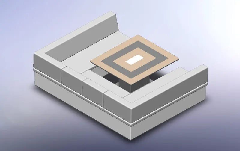
- MIDDLE SEAT
Middle seat was placed in the shaded area closely to the superstructure backdoor. Unlike the front seat and rear seat, the middle seat is designed using sloid modellingcommands.
Commands used : Sketch, Offset entities, Extrude boss, Extrude cut, Combine, Fillet, Chamfer, Mirror.
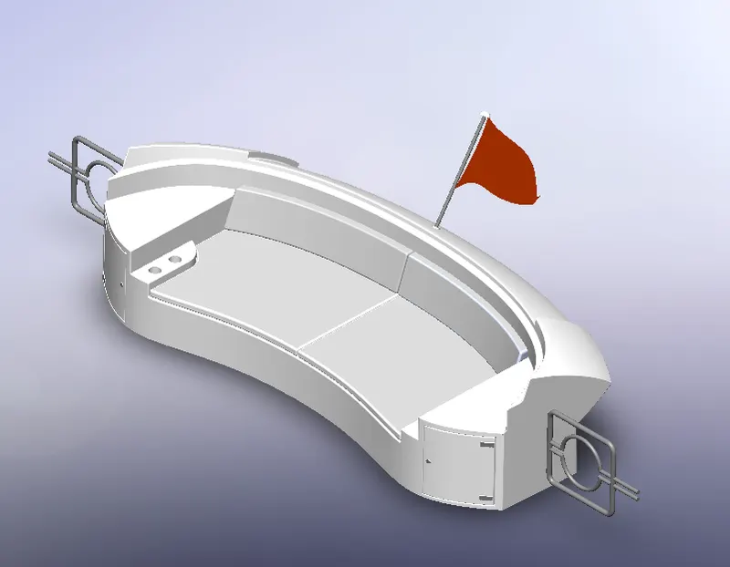
- REAR SEAT
Rear seat was placed over the garage behind the superstructure . It was designed after importing the deck surface of the hull as interface surface.
Commands used : Sketch, Offset entities, Swept surface, Offset surface, Trim surface, Ruled surface, Knit surface, Extend surface, Extruded surface, Lofted surface, Extruded boss, Extruded cut, Chamfer, Fillet, Swept boss, Mirror, Revolved boss.
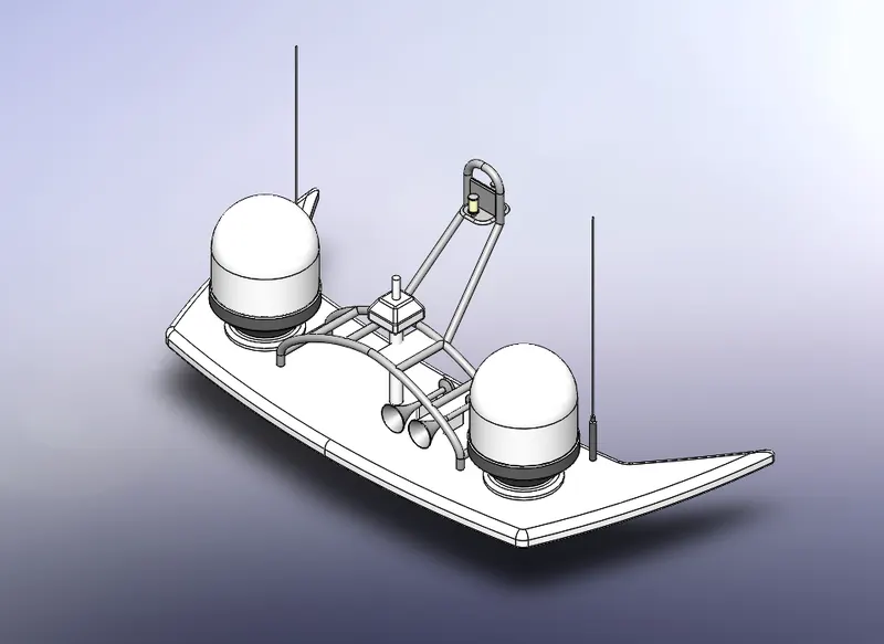
- RADAR MAST
The radar mast supports the radar,antennas, satellite domes and lights. It was designed after importing the top surface of superstructure as interface surface.
Commands used : Sketch, Offset entities, Extruded boss, Fillet, Revolved boss, Swept boss, Mirror, Project curve, Chamfer, Dome, Shell.
ASSEMBLY :
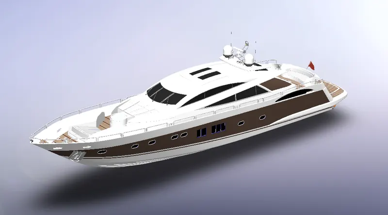
Assembeld the parts of yacht using Standard mates (Coincident, Concentric, Distance mates).
Plane orientation/ alignment was care while performing the mates. Since interface surface was used in designing some of the parts, no specific mates were used in such cases.
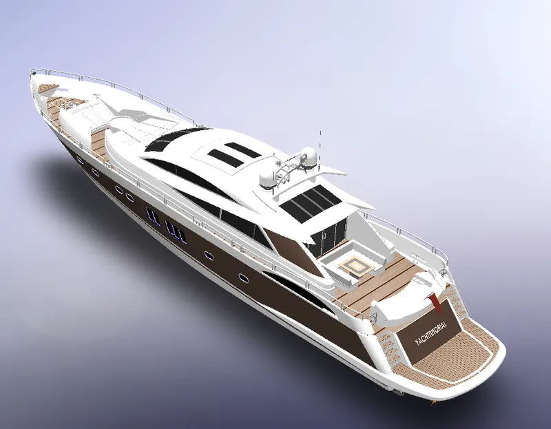
- ISOMETRIC VIEW
- CAMERA VIEW
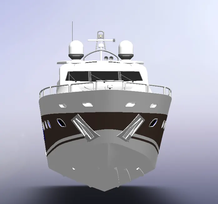
- FRONT VIEW
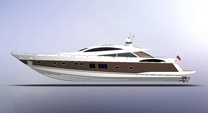
- SIDE VIEW
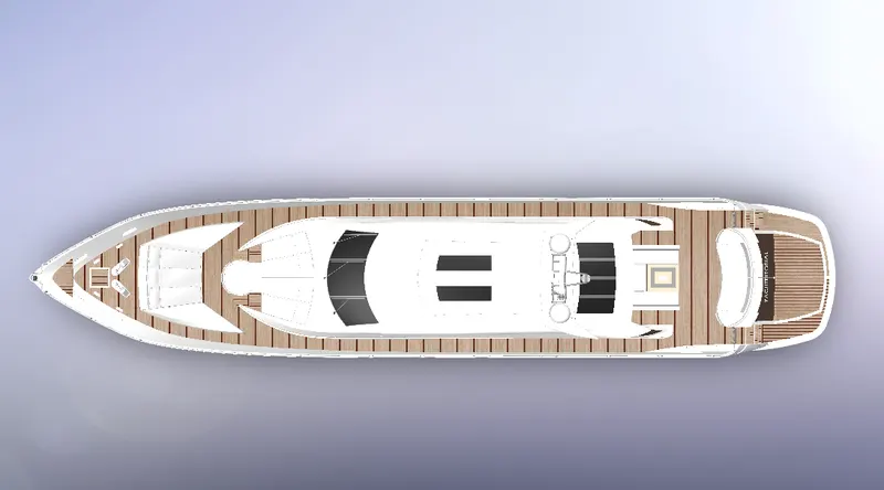
- TOP VIEW
RENDERING :
Rendering the model was done using the Photoview 360 and Solidworks visualize.
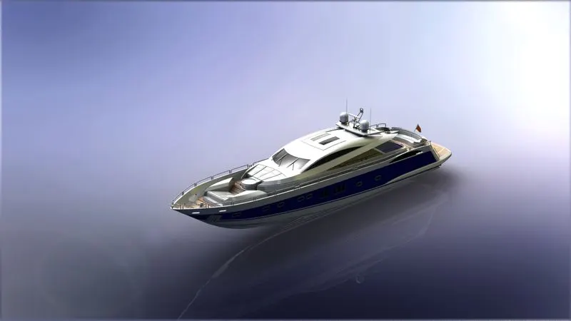
- PHOTOVIEW 360
Rendering using photoview 360 involved setting the Scene, Environmment, camera, Perspective and Lights by adjusting various parameters. Extra mates where added to give more realistic views of the scene.
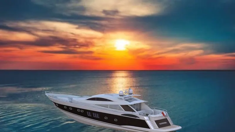
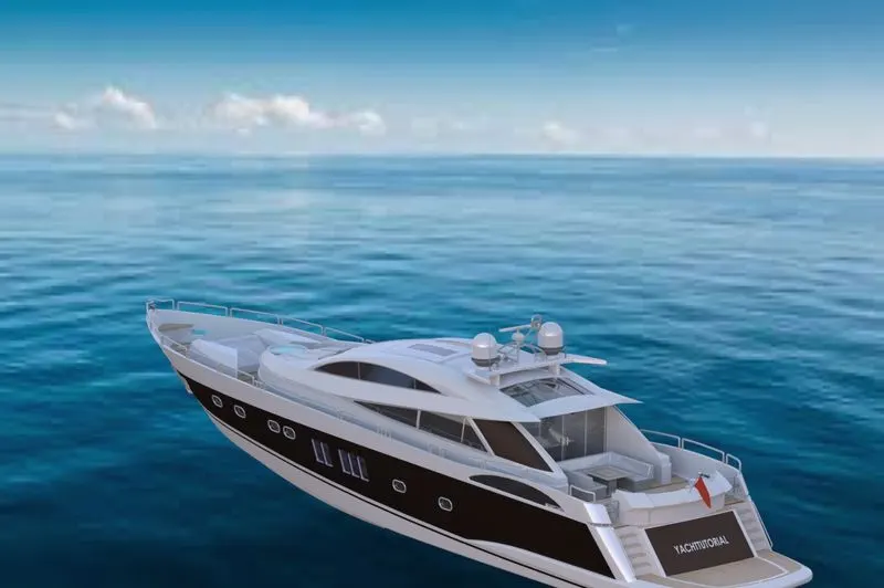
- SOLIDWORKS VISUALIZE
The assembly was imported to solidworks visualize and various adjustments of colour were done incase of multiple rendering. The Environment, Backplate and Camera position were choosen and tweated accordingly to give the image a photorealistic image
CONCLUSION:
Thus the exterior parts of an sunseeker predator yacht were designed, modelled and assembeld using solidworks 2018 and photorealistically rendered using solidworks visualize 2018.