Photo Realistic Rendering
DESIGNING A 3-D MODEL OF AMERICAN CHOPPER IN SOLIDWORKS
Objective:
To design the parts and components of an American Chopper bike, to assemble the parts that have been designed in SolidWorks, and to render the bike using SolidWorks Visualize
Introduction:
A motorcycle like American Chopper consists of many individual parts. So, they have to be modelled separately at first. Then all the components of the Chopper that are already designed must be assembled together to form the real structure of the vehicle. Many complicated features of SolidWorks software have been used to complete the designing process. Once a product has been developed, it is important to showcase it in the best possible way. Here comes the role of rendering. A stand-alone software called SolidWorks Visualize has been used to render the American Chopper assembly.
Since there are several parts that comprise the Chopper assembly, it makes sense to know the list of components that make up the motorcycle. Following are the parts present in the Chopper:
- Front fender
- Kickstand
- Rear fender
- Transmission belt
- Chain
- Oil tank
- Pedal
- Front wheel
- Front fork
- Rear wheel
- Chassis
- Engine
- Gas tank
To design an entire vehicle, a step-by-step approach is necessary to determine the order in which the parts can be modelled. Since most of the components would be dependent on other components, it is vital to identify the parts whose shape/structure is independent of others. In this regard, the next section deals with the design methodology which has been used in this project to model the individual components.
Design approach:
Designing the American Chopper has been divided into 7 tasks. In each task, some of the components present in the final assembly are modelled. For example, in the first task front fender, kickstand, rear fender and transmission belt were created. This is done in order to make it easy at the beginning since all these parts are small components and present in the exterior portion of the motorcycle. Likewise, in the consecutive tasks, the complexity of the models increases, and the interior portions of the bike are designed.
Essentially, the design approach used in this project is based on the concept of Reverse Engineering. The sketch picture of the American Chopper is taken, and the important parts of the vehicle are constructed according to the shape / structure of the motorcycle given in that image. For instance, the gas tank of the motorcycle has been modelled in this way. Similarly, the methodology in which the components are designed is bottom-up design. This approach is explained clearly with the help of the flowchart given below.

To make an entire sketch of the Chopper at a single stretch is time consuming and inefficient. There is also a danger of losing the data if the single file containing the assembly is corrupted. However, if the parts are modelled separately prior to the creation of assembly, it is easier to measure the progress as well as simpler to create an assembly. In this way, an assembly can be recreated from the scratch even if the assembly file gets lost or damaged. Individual component files reduce the complication as well as the danger of losing information.
Description:
Firstly, the front fender of the vehicle has been designed using SolidWorks in the part drawing mode. This component is colloquially termed as mudguard because it prevents the dust from splashing onto the motorcycle from the road due to the rotation of the tire. Easiest way of approaching the design is to consider the view that has more information, to draw a 2D sketch on the relevant plane using the sketch tab and to generate a 3D version of the part using the elements present in the feature tab. Here the front fender is modelled by revolving the figure drawn using the Sketch tab.
As it can be seen from the image given below, all the edges have been rounded off using the fillet command in the feature tab. It is done to remove any sharp endings in the surface and the boundary of the component. Also, the shell feature has been applied to the inner face of the fender to give a realistic look as it is the case in real-time scenarios. After developing the 3D model, the appearance of the part can be specified to avoid the monotonous look for all the components. Hence, Sienna has been applied to the part by simply dragging and dropping the corresponding appearance onto the surface of the fender.
The rear fender can also be constructed in a similar fashion except the fact that it has a quite different structure. So, once the sketch is drawn in the appropriate plane according to the shape, the respective sketch can be developed into a 3D model using the same procedures used to create the front fender.
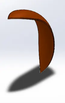
Figure 1: Front Fender
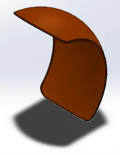
Figure 2: Rear Fender
Rear fender is a little bit broader than the front fender due to the fact that the rear wheel is wider in comparison to the front wheel. It can be observed in the following sections and the reason why the rear wheel has been designed broader is because the increase in contact surface area with the road offers strong grip, thereby preventing the possibility for slipping, toppling and avoiding accidents.
Kickstand, also known as side stand, is an element which supports the bike when it is at rest. It can be closed again to occupy its initial position when the bike is about to be in motion. The surface of the bottom portion of the kickstand has to be modelled carefully such that it establishes sufficient contact with the ground to withstand the motorcycle when it is leaning on the support of the side stand. In this regard, a small part of the kickstand has been removed using the split tool in Features tab so that it is flat and stable. The following figure depicts the isometric view of the kickstand.
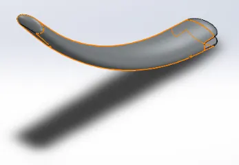
Figure 3: Kickstand
Power transmission is an important parameter to be considered in every automotive vehicle. In this chopper, belt drive is used to fulfill this purpose and the following figure illustrates the transmission belt in this motorcycle.
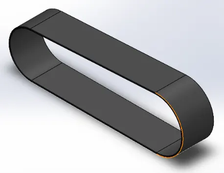
Figure 4: Transmission Belt
3D components of these 4 components were accomplished at the end of task 1. Therefore, as an objective of task 2, parts such as chain, oil tank and pedal have to be constructed using SolidWorks. When considering the design of the chain located in the Chopper, it can be observed that 2 distinct elements repeat themselves to form the whole structure. Thus, using a template or repeating the pattern would prove to be fruitful as well as efficient in creating the part model. In this way, the entire chain has been modelled in SolidWorks by creating solid blocks of the two unique elements.
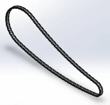
Figure 5: Chain
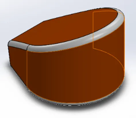
Figure 6: Oil Tank
The next component that has been constructed in this task is the oil tank. This is used to store oil and regulate it in appropriate intervals as per the requirement. Since the oil tank comes under the gas tank of the vehicle, its shape has to be designed perfectly such that the compact structure fits precisely within the given frame. This idea about the dimensions can be obtained from the sketch picture of the American Chopper.
The final component that has to be modelled in this task is the pedal. It is also known as footrest where the foot of the rider can be rested when the motorcycle is in motion. The pedal is present on both the sides of the chassis and hence the shape of the component on one side seems like a reflection in the mirror on the other side. In this manner, the left hand side pedal is mirrored using the features tab and saved as a separate part file for future use. The figure shown below projects the pedal in its isometric view to get a better understanding of its structure.
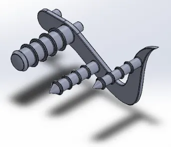
Figure 7: Pedal
In the next task, we move on to somewhat more important and bigger elements in the vehicle. Wheel is a significant component that aids in the movement of the Chopper and the front wheel is constructed using SolidWorks in this task. While designing the part, almost all the options in the feature tab were used for its development since it consists of various solid bodies such as rim, rotor, caliper, and tire that possess different forms. Like the rear fender, the rear wheel also looks more or less similar to the front wheel. Therefore, the same procedure has been used to model the rear wheel as well.
But at the same time, the rear wheel cannot be mirrored simply using the command available in the feature tab like we did for the pedal. Here some structures differ in a certain way because the rear wheel is not exactly the mirror image of the front wheel. Hence, the rear wheel is constructed as a separate part drawing file and both the images of the wheel models are displayed in the next page.

Figure 8: Front Wheel
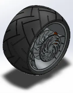
Figure 9: Rear Wheel
For example, it can be observed that the breadth of the rear wheel is much wider than the front wheel. Adding to that, it also has a provision for chain sprocket on which the chain can be placed over. When the wheels are designed, it is also important to construct the front fork with which the direction of the vehicle can be controlled, thus maintaining the stability in rotation of that, which has been called as the handlebar. This component of the motorcycle comprises lights, suspension fork, cable wires, and the huge benefit is that if one side of the chopper is modelled, the other side can be mirrored out from it as they are symmetrical in nature.
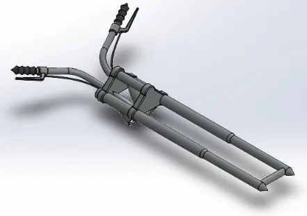
Figure 10: Front Fork
It is evident from the above figure that the part would be clamped to the frame of the vehicle and locked within certain limits so that the front fork can be turned only up to a particular angle. In the next task, most significant components of the vehicle are designed, which are the chassis and engine of the motorcycle.
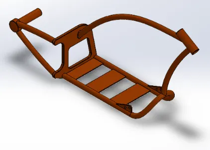
Figure 11: Chassis
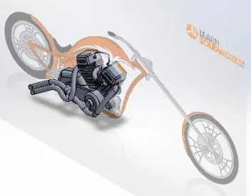
Figure 12: Engine
From the image of the chassis, it is clear that it is the part that houses or constitutes most components of the American Chopper. With reference to the planes of the chassis, all the parts of the motorcycle are mated into the assembly. The next figure illustrates the engine on a backdrop of a sketch picture of the vehicle, which has been used for the purpose of approximating the positions of sub-components within the engine with respect to the origin. As it can be seen from the above figure, the engine has been modelled using sophisticated features like composite curves in SolidWorks. Most of the commands were utilized to construct the whole structure since it is a complicated part with significant functionalities.
Eventually, the gas tank of the Chopper encompasses the vital elements of the motorcycle beneath it and also has the additional utility of storing as well as regulating the fuel to the engine. This component shall be included to the assembly by aligning it with the front plane of the chassis so that even if the entire assembly is moved, the gas tank moves along with the vehicle as a part of it.
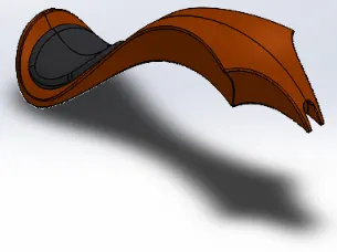
Figure 13: Gas Tank
Now that all the parts have been added to the assembly, it is important to make any single major component as a fixed entity to ensure that the mate definitions are standardized on this basis. In this regard, chassis has been fixed so that all other elements can be included in the assembly by defining relations with the planes of the chassis. In this manner, the complete design of the American Chopper has been developed using SolidWorks and the following figure represents the whole assembly of the motorcycle.
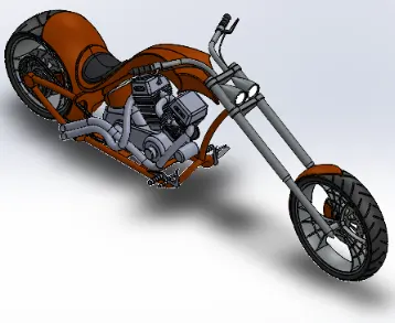
Figure 14: Isometric view of the vehicle after assembling all the individual parts
As the assembly model of the vehicle has been created, the appearances and aesthetics of the Chopper can be improved or modified to give the design an appealing look. In this regard, the color of the chassis has been changed and few decals have been added to the surface of the parts.
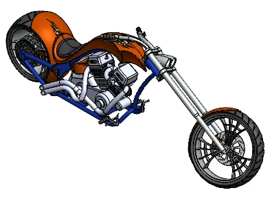
Figure 15: Same view of the vehicle with some features improvised
The images attached below depict the different views of the motorcycle with the inclusion of some decals and optimized visual appearance.
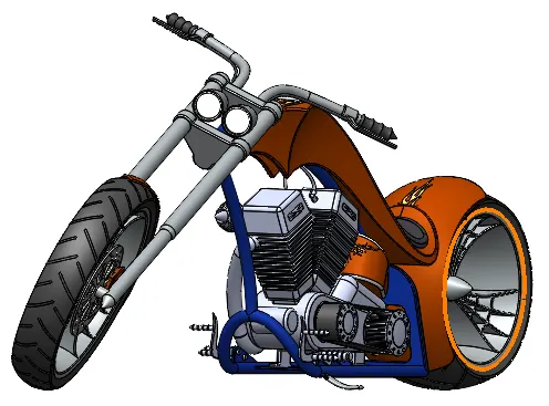
Figure 16: Camera setup view of the assembly model
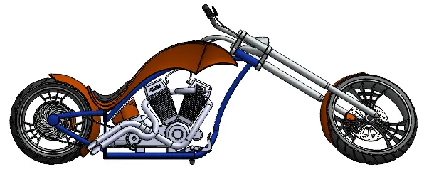
Figure 17: Side view of the American Chopper
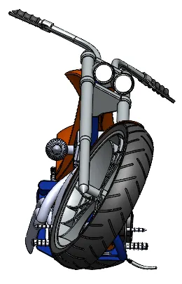
Figure 18: Front view of the motorcycle
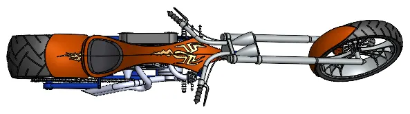
Figure 19: Top view of the vehicle with newly added decals
After constructing the CAD model of American Chopper, the data has to be rendered so that it can be presented professionally in an appealing manner. To optimize the appearance of the design, the entire model has been rendered using the standalone product SolidWorks Visualize. Route 66 backdrop has been chosen to project the motorcycle in a natural environment realistically. Fast render has produced the quality of the images that are shown in the following pages and number of passes have been given around 53 to obtain a quick render.
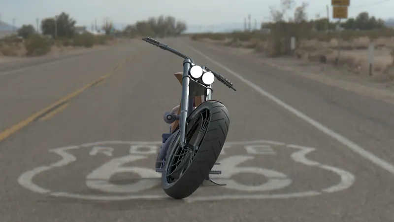
Figure 20: Rendered image of the vehicle - Front view
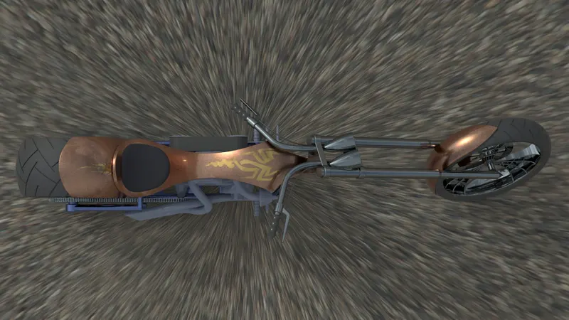
Figure 21: Rendered image of the American Chopper - Top view
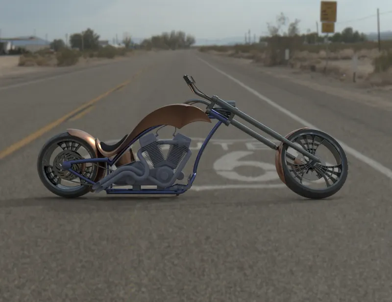
Figure 22: Rendered image of the motorcycle - Side view
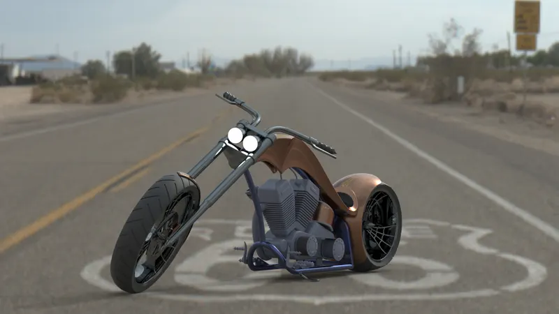
Figure 23: Rendered image - Camera setup view
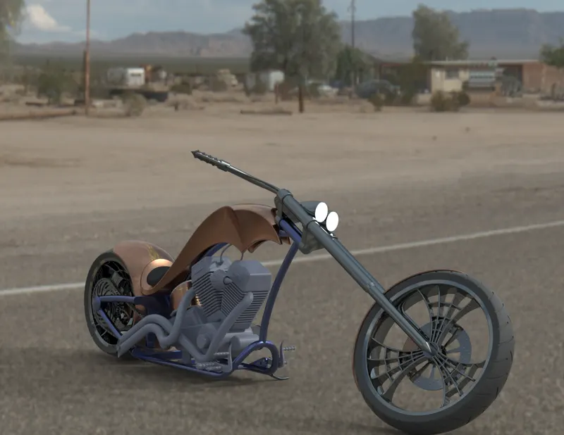
Figure 24: Rendered image of the vehicle - Isometric view
It could be observed from the above images that some portions of the Chopper are shiny which denotes that they reflect sunlight from their surface making the scene to look normal. There were also other backgrounds, but Route 66 has been preferred over others due to its appropriateness with respect to the motorcycle when it is placed in the foreground. For instance, the above figure represents a two-wheeler parked on the road, on a sunny day. Since the image should look like a snap taken in real-time, the headlights displayed are seemed to be switched on and emit light as the result.
Conclusion:
All the individual components of American Chopper have been designed using SolidWorks and assembled together into a complete Assembly model. Then, the corresponding 3D model has been rendered using SolidWorks Visualize to present the visuals of the motorcycle in an attractive way. While progressing through the process of designing and rendering, lots of significant commands, features, and tools of SolidWorks have been utilized to develop the structure of the entire vehicle.
Additional Information:
Since my Laptop performance was very poor, I could do the rendering only for the assembly model of American Chopper. That too, I performed fast render, which took almost 75 minutes. As the processing is very slow in my PC, I did not render the individual part files separately. Please consider this while going through the report as well as the rendered images. For your reference, I am also attaching the corresponding URL below, which comprises all the relevant part files and the assembly model.
https://drive.google.com/drive/folders/1EzJt2_672il_008uXWogIOcoRUjbnO0D?usp=sharing