Performance Analysis of Three Lobe Bearings
* This project was in collaboration with Rahul Shagrithaya and under the guidance of Prof. Harish Kamat as part of the Graduate Project of the Bachelor's Degree in Mechanical Engineering at the Manipal Institute of Technology.
Objectives:
To study the hydrodynamic pressure, deformation, and stress distribution in three-lobe bearings and compare combinations of eccentricity ratios and materials.
Methodology:
Two-phase Computational Fluid Dynamics (CFD) and Two-way Fluid-Structure Interaction (FSI) considering cavitation. System coupling between static structural and fluent modules in Ansys Workbench.
Software Used:
Autodesk Fusion 360 for modelling and Ansys Workbench for CFD and FSI.
About the Project:
The standard hydrodynamic journal bearings are unstable at high speeds and can damage the machinery. Non-circular bearings can be used in this case. Lobe bearings are one such type of non-circular bearings that can significantly increase load carrying capacity and stabilize the shaft. The graduate project analyses the performance of three-lobe bearings using CFD and FSI analysis considering various bearing materials and lubricants.
Three-Lobe Bearings:
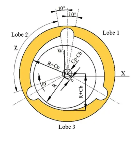
These bearings have three lobes placed at 120° to each other, with three 20° grooves between them that have holes on the top that act as the inlet for the lubricant.
The shaft is offset by a small amount from the centre of the bearing to maintain an eccentricity. The lubricant flows between the shaft's outer surface and the bearing's inner surface and gets pushed out of the system from the sides of the bearing.
CFD and FSI Analysis:
A system coupled between two-phase (liquid and vapour phase) Computational Fluid Dynamics and two-way Fluid-Structure Interaction was used to measure the fluid pressure of the lubricant on the bearing and the shaft, and the geometrical deformation of the fluid and the solid domain.
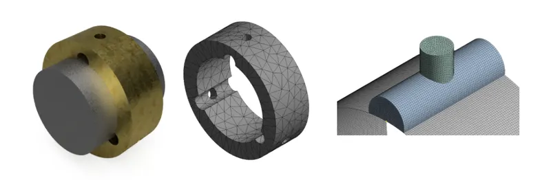
A complete model including the bearing, shaft, and fluid domain was modelled on Fusion 360 and meshed on Ansys Workbench.
Ansys Workbench Modules:
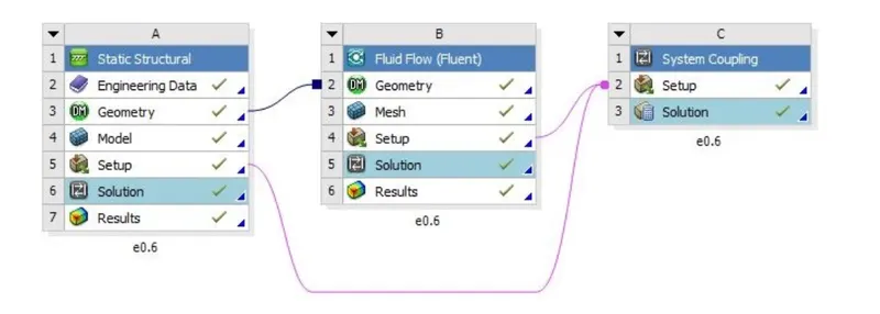
Static structural and fluent modules were coupled together using the system coupling module in Ansys Workbench. The bearing and the shaft model were imported into the static structural module and the fluid domain was imported into the fluent module.
Eccentricity ratios and bearing material used:
24 combinations were created using these eccentricity ratios and materials and were analyzed and compared.
| Eccentricity Ratios | 0.25, 0.4, 0.6, 0.75 |
| Lubricants | ISO-VG32, Water |
| Bearing Materials | Brass, Structural Steel, Bronze |
| Shaft Material | Structural Steel |
Results:
The following data for all 24 combinations were obtained:
- Fluid Pressure of Lubricant
- Bearing Deformation
- von-Mises stress on the bearing
Conclusions:
The following conclusions were drawn from the work:
- Eccentricity ratio has a substantial effect on the concentration of pressures over the bearing
- The fluid pressure for a given lubricant and eccentricity ratio remains constant regardless of the bearing or shaft material
- Fluid pressure, bearing deformation, and von-misses stress in the bearing increases with an increase in eccentricity ratio
- Multi-lobe bearings should be designed to be used with lower eccentricity ratios for optimal performance
- An increase in eccentricity ratio decreases the attitude angle at a given shaft speed
- ISO VG32 produces more fluid pressure, bearing deformation, and von-misses stress in the bearing than Water
- Deformation and stresses induced in the bearing were least when structural steel was used, followed by bronze, and then brass
Data obtained for Eccentricity ratio 0.75:
Similar data were obtained for 0.25, 0.4, and 0.6 eccentricity ratios.