Otto cycle Project for engine kinematics
Aim:
To write code that can solve an otto cycle and make plots for it.
Requirements:
Here are the requirements
- Your code should create a PV diagram
- You should output the thermal efficiency of the engine.
Introduction & Procedure :
Otto cycle
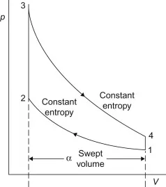
The Otto cycle was developed by German engineer Nikolaus Otto in 1876. This cycle is very similar to the Diesel cycle, except that the Otto cycle forms the basis of a spark-ignition (S.I.) engine, which requires a spark to begin combustion of fuel. Figure represents a P-V diagram of an Otto cycle.
- Also known as Constant volume cycle as heat is recieved and rejected at constant volume.
- The otto cycle consists of two constant volume and two reversible adiabatic processes.
-
First stage(reversible adiabatic or isentropic compression)
Air is compressed reversibly and adiabaticaly from temperature t1 to temperature t2. in this process, no heat is absorbed and rejected by air.
- .Second stage(constant volume heating addition)
Heat addition starts at point 2 and ends at point 3. A quantity of heat Qin is added at constant volume, and the working fluid temperature rises. Air is heated at constant volume and temperaure reaches t2 to t3 while volume remains same.
5. Third stage(reversibly adiabatic or isentropic expansion)
The isentropic expansion process starts at point 3 and it ends at point 4 to the original volume. Air is expanded reversibly and adiabaticaly from temperature t3 to temperature t4. in this process, no heat is absorbed and rejected by air.
6. Fourth stage(constant volume cooling)
The heat Qout is rejected at constant volume from point 4 to point 1. Air gets cooled and the working fluid temperature goes down at a constant volume until the cycle is completed.
- Air is cooled at constant volume and temperaure reaches from t4 to t1 while volume remains same.
Engine geometric parameters:
1) Bore , 2) stroke , 3) connecting rod length[con_rod ] , 4) crank radius[cr ]
with these known parameters, we can calculate piston design , & swept volume & clearance volume
Procedure:
- Isentropic processes are adiabatic reversible processes and the state variables obey the following equations:
`P 1 ⋅ V 1 ^γ = P 2 ⋅ V 2 ^γ`
`T 1 ⋅ V 1 ^(γ − 1) = T 2 ⋅ V 2^( γ − 1`
- Isochoric processes take place in a constant volume and pressure and temperature obey ideal gas law:
`V 1 = V 2`
`(P 1) /(T 1) = (P 2)/( T 2)`
Assume `gamma`= 1.4
- Thermal efficiency
`thermal_eff = [1-(1/(cr^(gamma-1)))]*100`
-
Engine Properties:
The following engine parameters define its performance:
- Stroke (s = 0.1)
- Compression Ratio (cr = 12)
- connecting rod length(con_ rod)= 0.15
- bore= 0.1
Using these values remaining parameters can be derived:
connecting rod length
Crank pin radius =`r = s/2`
Swept volume= `( V s = π /4 ⋅ (BORE )^ 2 ⋅ stroke)`
Clearance Volume = `V c = (Vs )/(c r − 1 )`
Volume of the chamber during the compression and expansion strokes is governed by the crank rotation and is related to the crank angle (t) and crank ration(R) as follows:
`V = V c + (V s)/ 2 ⋅ ( 1 − cos ( t ) + R − ( R^ 2 − sin ( t )^ 2 ) ^0.5 )`
This equation can be used to generate a data set for volume during the isentropic cycles for a given range of crank angle(t1 to t2)
Main:
- Standard atmosphere was used as initial conditions for pressure, temperature and the volume has been derived from engine properties.
- Cycle properties were used to determine the limiting state points for each process and plotted in figure 1
- The volume function is then used to plot the path for isentropic processes in figure 3.
- Figure 2 was generated to visualise the change in volume with respect to crank angle.
- And the program ends by displaying efficiency calculated using above mentioned equation.
Main code
clear all; close all; clc;

%input
gamma= 1.4;
t3= 2300;

%state variable
p1= 101325
t1= 500

%engine geometric parameters
bore= 0.1;
stroke= 0.1;
con_rod= 0.15;
cr= 12;

%calculating the swept volume & the clearance vol
v_swept= (pi/4)*bore^2*stroke;
v_clearance= v_swept/(cr-1);
v1= v_swept + v_clearance;
v2= v_clearance

%state variable at state 3
%p2v2^gamma= p1v1^gamma
%p2= p1*(v1/v2)^gamma= p1*cr^gamma
p2= p1*cr^gamma;

%p1v1/t1= p2v2/t2 | t2= (p2*v2*t1)/(p1*v1)
t2= (p2*v2*t1)/(p1*v1);
constant_c= p1*v1^gamma;
V_compression= engine_kinematics(bore,stroke,con_rod,cr,180,0);
P_compression= constant_c./V_compression.^gamma;

%state variable at point 3
v3= v2
%p3v3/v3= p2v2/t2 | p3= p2*t3/t2
p3= p2*t3/t2
constant_c= p3*v3^gamma;
V_expansion= engine_kinematics(bore,stroke,con_rod,cr,0,180);
P_expansion= constant_c./V_expansion.^gamma;

%state variable at point 4
v4= v1
%p3v3^gamma= p4v4^gamma | p4= p3*(v3/v4)^gamma
p4= p3*(v3/v4)^gamma

%plotting ott cycle curves
figure(1)
hold on
plot(v1, p1, '*','color','r')
plot(V_compression, P_compression, 'linewidth',2,'color','g')
plot(v2, p2, '*','color','r')
plot([v2 v3], [p2 p3], 'color', 'b') % to join v2 v3 & p2 p3 line from 2 to 3
plot(v3, p3, '*','color','r')
plot(V_expansion, P_expansion, 'linewidth',2,'color','b')
plot(v4, p4, '*','color','r')
plot([v4 v1], [p4 p1],'color','y') % to join v4 v1 & p4 p1 line from 4 to 1
legend('p_1,v_1','Adiabatic Compression','p_2,v_2','Const.Vol Heat input','p_3,v_3','Adiabatic Expansion','p_4,v_4','Const.Vol Heat Rejection')
xlabel('volume in m^3')
ylabel('pressure in Pa')
title('PV diagram Otto cycle as a path function')

%to connect p1 p2 p3 p4, v1 v2 v3 v4
figure(2)
plot([v1 v2 v3 v4 v1], [p1 p2 p3 p4 p1],'color','b')
title('PV Diagram Otto cycle as a state function')

% Thermal Efficiency of an Otto cycle
thermal_eff = [1-(1/(cr^(gamma-1)))]*100
Creating a function that returns the Engine kinematics process :
In a Matlab script create a function as shown above with the return value being Volume in the cylinder, function name being engine_kinematics( any name can be assigned), and the input variables will be bor, stroke, length of connecting rod, starting crank angle, ending crank angle like this,
function [V] = engine_kinematics(bore,stroke,con_rod,cr,start_crank,end_crank)
In the body of the function calculate crank pin radius, swept volume, clearance volume and initialize the angles of the crank rotation.
`V c (1+ 1/2(cr-1)) ( 1 − cos ( theta ) + R − ( R^ 2 − sin ( theta )^ 2 ) ^0.5 )`
This is a geometrically derived equation which exactly determines the volume of the cylinder at any instant of the rotation of the crank which is found to have exact same values as determined by Adiabatic condition. Using this equation, the volume in the cylinder is returned.
- The function is closed using an 'end' command.
- The function program should be saved with the same name as that of the function. And it should be saved in the same folder as that of the main program which calls this function.
The Matlab program for the function is below.
function [V] = engine_kinematics(bore, stroke, con_rod, cr, start_crank, end_crank)

a= stroke/2
R= con_rod/a
v_s= (pi/4)*bore^2*stroke;
v_c= v_s/(cr-1);

%formula for how the volume inside a combustin chamber change
%v/vc= 1 + 0.5(rc-1)[R+1- cosd(theta)- (R^2 -sin^2(theta)^0.5]
% rc= cr
%crank angle theta= 0
theta= linspace(start_crank, end_crank, 100);
%break formula into terms
term1= 0.5*(cr-1);
term2= R+1-cosd(theta);
term3= (R^2-sind(theta).^2).^0.5;
V= (1 + term1*(term2- term3)).*v_c;

end
Result :
Figure 1:
Figure 2:
Command window outputs:
Error faced:
error faced in line 32
V_compression is a array containing matrix so we have to use ' .' pointwise operator for dot product of
(P_compression= constant_c./V_compression.^gamma) % this is right syntax