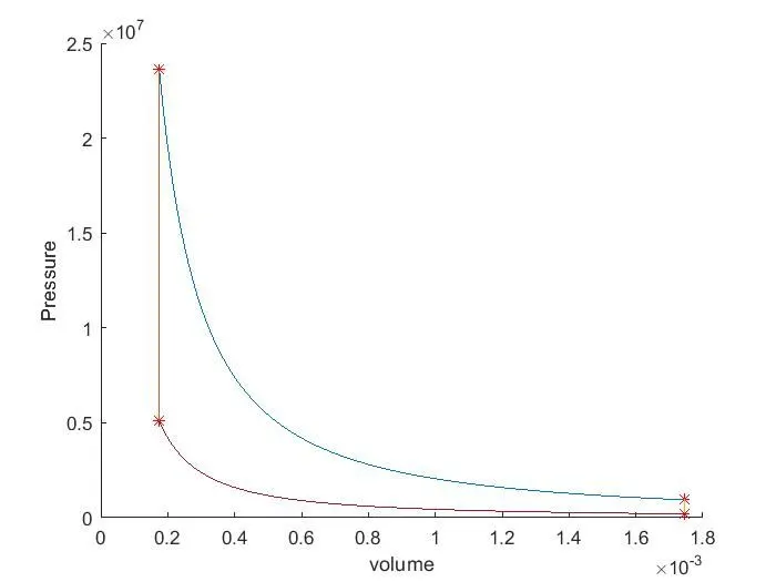
Otto Cycle P-V Diagram & thermal efficiency
%Write code that can solve an otto cycle and make plots for it
Otto cycle-
It is a theoretical thermodynamic combustion cycle that describes the function of a four-stroke spark-ignition engine. It consists of the following internally reversible processes.
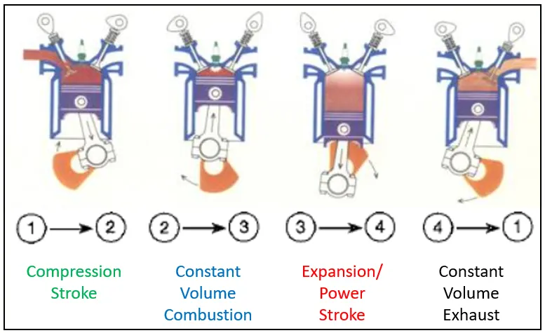
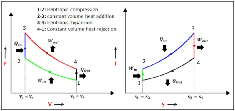
Process 1-2
At the start of this process, Piston is at the Bottom Dead Centre(BDC) of the engine cylinder & the Cylinder is filled with the air-fuel mixture. During this process, the piston moves from BDC to Top Dead Centre(TDC) compressing the fuel mixture. So temperature & pressure increases. In this isentropic process, no heat is exchanged i.e. adiabatic and process 1-2 is completed.
P1V1ϒ = P2V2ϒ
ϒ(Gamma) = Specific Heat Ratio
Process 2-3
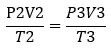
This is the combustion stroke as the spark plug is ignited & the fuel mixture is burnt producing lots of thermal energy at constant clearance volume. The combustion is complete at state 3 with increased Pressure & Temperature due to high thermal energy storage.
V2= V3
Process 3-4
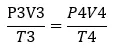
During this process, stored thermal energy pushes the piston from TDC to BDC as chamber volume increases i.e. thermal energy is converted to motion hence called the power stroke. Pressure & temperature decrease.
P3V3ϒ = P4V4ϒ
Process 4-1
This process is called exhaust stroke as the fuel mixture is released at constant volume. Hence pressure & temperature decrease further & state 1 is achieved again.
V4= V1
Swept Volume Vs- The volume of cylinder swept by cylinder b/n TDC & BDC.
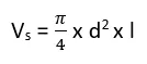
d = Piston bore diameter
l = Length of stroke
Clearance Volume Vc- Volume of the engine above TDC & combustion is done when the volume of the engine is compressed to clearance volume.

Cr = Compreaaion Ratio = V1/V2 = (Vs + Vc)/Vc
Total volume V1 = Vs + Vc
Volume & Crank-angle Relation

V = Volume of engine cylinder at crank angle of Θ
rc = Compression Ratio
R = Ratio of connecting rod length & crank pin radius
a = crank pin radius = stroke length / 2
Thermal Efficiency of Otto Cycle-
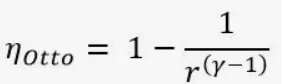
r = compression ratio
Generally below inputs are known, hence assumed as
Stroke length = 0.2 m
Bore/Cylinder Diameter = 0.1 m
Connecting rod length = 0.3 m
Compression ratio = 10
Initial state parameters are assumed as
P1 = 202650 Pa
T1 = 300K
T3 = 3500K
gamma = 1.4 (Assumed to be diatomic gas medium)
Program#1 (For plotting & Thermall efficiency calculation)
% Assignment5_Otto Cycle Solution & Plottings

%%Assumptions
%State1 Parameters in SI units
P1=202650;
T1=300;
%State3 Parameters in SI units
T3=3500;

%Inputs in SI units
strokelength = 0.2;
boredia = 0.1;
Con_rod_length = 0.3;
Cr = 10 ;
gamma = 1.4;

%Swept Volume
V_s = pi/4 * boredia^2 * strokelength;

%Clearance Volume
V_c = V_s / (Cr - 1);

%%State Variable at point1
V1 = V_s + V_c;

%%State Variable at point2
V2 = V_c;
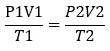
%Adiabatic 1-2 process, P1V1^gamma = P2V2^gamma, P1V1/T1 = P2V2/T2
P2 = P1 * (Cr^gamma);
T2 = T1 * ((P2*V2)/(P1*V1));

%P1V1^gamma = constant
Constant = P1 * V1^gamma;

Compression_volume = Variablevolume(strokelength,boredia,Con_rod_length,Cr,180,360);
Compression_pressure = Constant ./ (Compression_volume.^gamma);

%%State variable at point3
V3 = V2;
%Reversible 2-3 process, P2V2/T2 = P3V3/T3
P3 = P2 * (T3/T2);

Constant = P3 * V3^gamma;

Expansion_volume = Variablevolume(strokelength,boredia,Con_rod_length,Cr,0,180);
Expansion_pressure = Constant ./ (Expansion_volume.^gamma);

%%State Variable at point4
V4 = V1;
%Adiabatic process 3-4, P3V3^gamma = P4V4^gamma, V4/V3 = V1/V2 =Cr
P4 = P3/(Cr^gamma);
%Reversible process, P1V1/T1 = P4V4/T4
T4 = T1 * (P4/P1);

hold on

plot(V1,P1,'*', Color='r')
plot(V2,P2,'*', Color='r')
plot(V3,P3,'*', Color='r')
plot(V4,P4,'*', Color='r')
plot(Compression_volume,Compression_pressure)
plot(Expansion_volume,Expansion_pressure)
plot([V2 V3],[P2 P3])
plot([V4 V1],[P4 P1])
xlabel('volume')
ylabel('Pressure')

%Thermal efficiecny of Otto cycle = 1 - (1/(Cr^(gamma-1)))
Thermal_efficiency = 1 - (1/(Cr^(gamma-1)))
Program#2(for calling function as Volume of the cylinder is related with crank angle)
function [Volume] = Variablevolume(strokelength,boredia,Con_rod_length,Cr,Start_angle,End_angle)

a = strokelength/2;
R = Con_rod_length/a;

V_s = pi/4 * boredia^2 * strokelength;
V_c = V_s / (Cr - 1);

theta = linspace(Start_angle,End_angle,100);

%Cylinder volume & Clearance volume relation

term1 = 0.5 * (Cr-1);
term2 = R + 1 - cosd(theta);
term3 = ((R^2)-(sind(theta).^2)).^(0.5);

Volume = (1 + term1*(term2 - term3)).*V_c
end
Results -
After executing the programs below result is obtained
>> Assignment5
Volume =
Columns 1 through 10
0.0017 0.0017 0.0017 0.0017 0.0017 0.0017 0.0017 0.0017 0.0017 0.0017
Columns 11 through 20
0.0017 0.0017 0.0017 0.0017 0.0017 0.0017 0.0017 0.0017 0.0017 0.0016
Columns 21 through 30
0.0016 0.0016 0.0016 0.0016 0.0016 0.0016 0.0016 0.0016 0.0015 0.0015
Columns 31 through 40
0.0015 0.0015 0.0015 0.0015 0.0014 0.0014 0.0014 0.0014 0.0014 0.0013
Columns 41 through 50
0.0013 0.0013 0.0013 0.0012 0.0012 0.0012 0.0012 0.0012 0.0011 0.0011
Columns 51 through 60
0.0011 0.0011 0.0010 0.0010 0.0010 0.0010 0.0009 0.0009 0.0009 0.0008
Columns 61 through 70
0.0008 0.0008 0.0008 0.0007 0.0007 0.0007 0.0007 0.0006 0.0006 0.0006
Columns 71 through 80
0.0006 0.0005 0.0005 0.0005 0.0005 0.0005 0.0004 0.0004 0.0004 0.0004
Columns 81 through 90
0.0004 0.0003 0.0003 0.0003 0.0003 0.0003 0.0003 0.0002 0.0002 0.0002
Columns 91 through 100
0.0002 0.0002 0.0002 0.0002 0.0002 0.0002 0.0002 0.0002 0.0002 0.0002
Volume =
Columns 1 through 10
0.0002 0.0002 0.0002 0.0002 0.0002 0.0002 0.0002 0.0002 0.0002 0.0002
Columns 11 through 20
0.0002 0.0002 0.0002 0.0003 0.0003 0.0003 0.0003 0.0003 0.0003 0.0004
Columns 21 through 30
0.0004 0.0004 0.0004 0.0004 0.0005 0.0005 0.0005 0.0005 0.0005 0.0006
Columns 31 through 40
0.0006 0.0006 0.0006 0.0007 0.0007 0.0007 0.0007 0.0008 0.0008 0.0008
Columns 41 through 50
0.0008 0.0009 0.0009 0.0009 0.0010 0.0010 0.0010 0.0010 0.0011 0.0011
Columns 51 through 60
0.0011 0.0011 0.0012 0.0012 0.0012 0.0012 0.0012 0.0013 0.0013 0.0013
Columns 61 through 70
0.0013 0.0014 0.0014 0.0014 0.0014 0.0014 0.0015 0.0015 0.0015 0.0015
Columns 71 through 80
0.0015 0.0015 0.0016 0.0016 0.0016 0.0016 0.0016 0.0016 0.0016 0.0016
Columns 81 through 90
0.0016 0.0017 0.0017 0.0017 0.0017 0.0017 0.0017 0.0017 0.0017 0.0017
Columns 91 through 100
0.0017 0.0017 0.0017 0.0017 0.0017 0.0017 0.0017 0.0017 0.0017 0.0017
Thermal_efficiency =
0.6019
Hence the efficiency of the Otto cycle for the given data is obtained as 60.19%.
The plot obtained is as shown