Multi Body Dynamics simulation on Planetary Gear Assembly
Aim:
To perform Motion Analysis on a planetary gear using SolidWorks and discuss the results for the following three cases:
|
S.No |
Input |
Output |
Fixed |
|
1 |
Sun Gear |
Carrier |
Ring Gear |
|
2 |
Ring Gear |
Carrier |
Sun Gear |
|
3 |
Sun Gear |
Ring Gear |
Carrier |
Introduction:
A simple planetary gear set is made up of three main components:
- The sun gear that sits in the centre (central gear)
- Multiple planet gears
- The ring gear (outer gear)
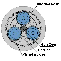
Source: https://www.apexdyna.nl/en/planetary-gearbox-introduction/
The three components make up a stage within a planetary gearbox. For higher ratios we can offer double or triple stages.
Planetary gearboxes can be powered by either electric motors, hydraulic motors or petrol or diesel combustion engines.
The load from the sun gear is distributed to several planetary gears which can either be used to drive an outer ring or a shaft or spindle. The central sun gear takes a high-speed, low-torque input. It drives several rotating external gears which increases the torque.
The simple design is a highly efficient and effective way of transferring power from a motor to an output. Approximately 97% of the energy input is delivered as an output.
Planetary gears are often used when space and weight are an issue, but a large amount of speed reduction and torque are needed. This requirement applies to a variety of industries, including tractors and construction equipment where a large amount of torque is needed to drive the wheels. Other places you will find planetary gear sets include turbine engines, automatic transmissions, and even electric screwdrivers.
Advantages of planetary gears:
- High efficiency
- Compact construction
- High power density
Disadvantages of planetary gears:
- Complex construction
- Higher power dissipation than with spur gears
- Complex bearings
Procedure:
Modelling:
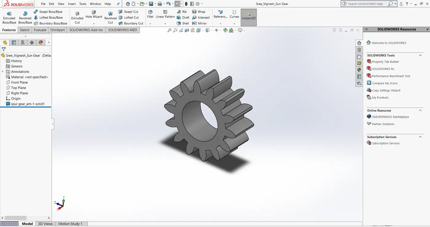
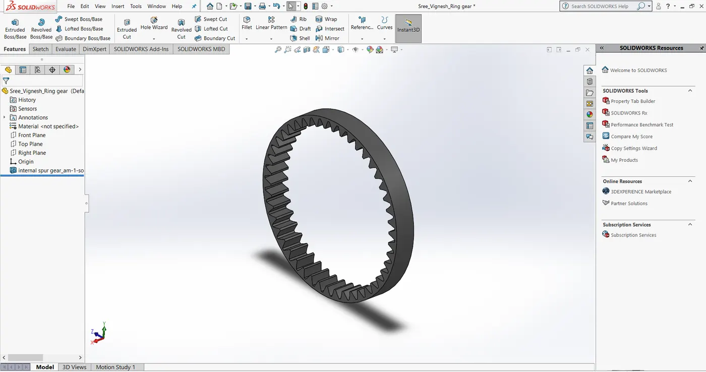
The sun gear, planet gear and the ring gear were modelled using the design library of SolidWorks.
The parameters considered are:
Ring Gear:
- Module = 2.5 (Metric system is used in design modeler)
- Number of teeth = 46
Sun Gear:
- Number of teeth = 14
Planet Gear:
- Number of planet gears = 4
Input speed of the gear = 200 RPM
Given that the module is same for all the gears, with the help of module formula `m = D/T` we can calculate the pitch circle diameter using the given values of module and number of teeth for each gear. Here, m is the module, D is the Pitch circle diameter and T is the number of teeth.
Thus, for Sun gear, the pitch circle diameter is 35 and for Ring gear, pitch circle diameter is 115
To find out the pitch circle diameter of planet gears, we can use the relation below:
`D_r = D_s + 2*D_p` (Diameter of Ring gear = Diameter of Sun gear + 2*Diameter of Planet gear)
Hence `D_p = 40`
The number of teeth for planet gears is calculated as 16 from the Module formula.
Sun Gear:
Ring Gear:
Planet Gear:
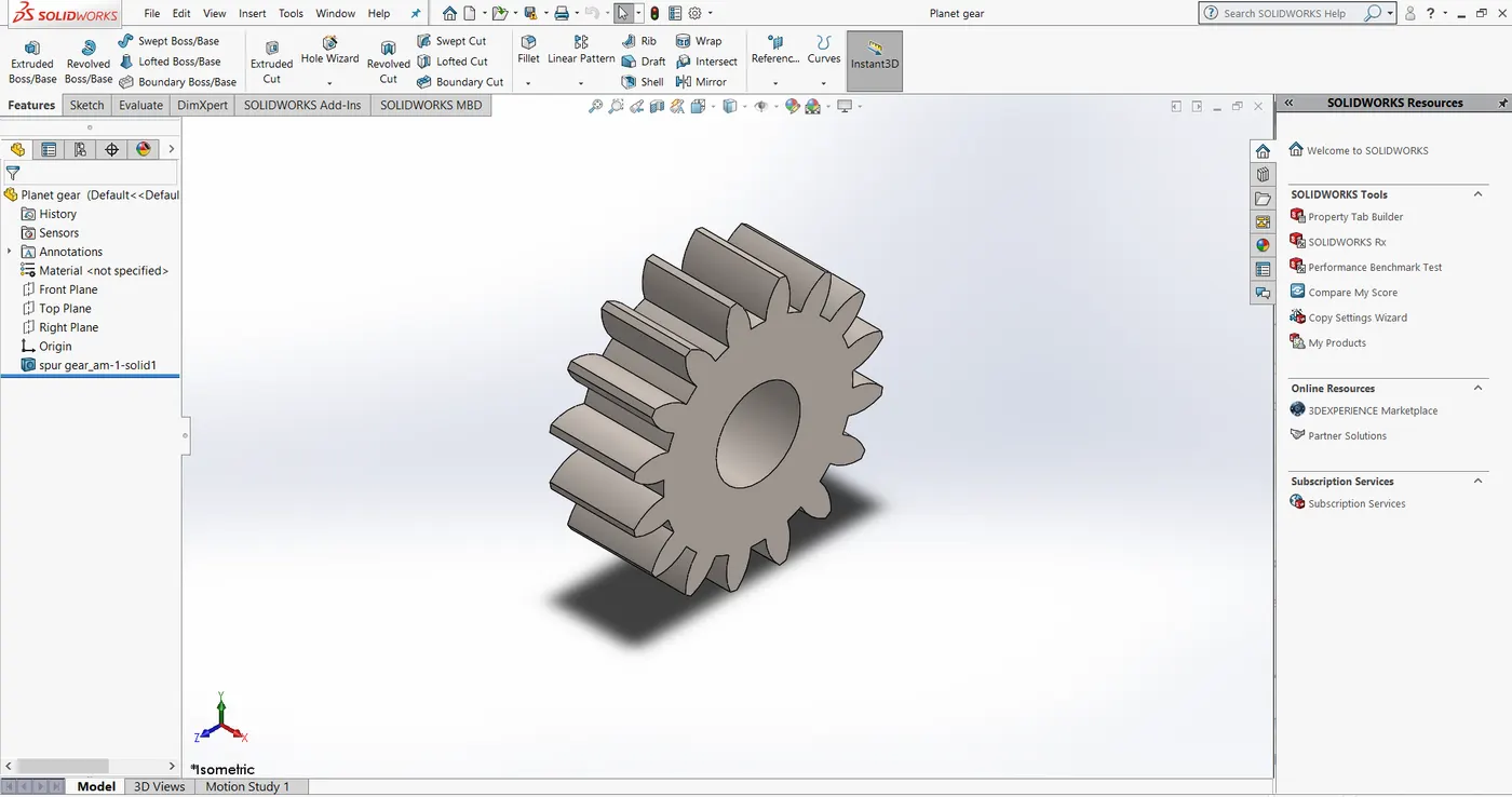
The number of planet gears is 4 and the number of teeth of each of these gears is 16
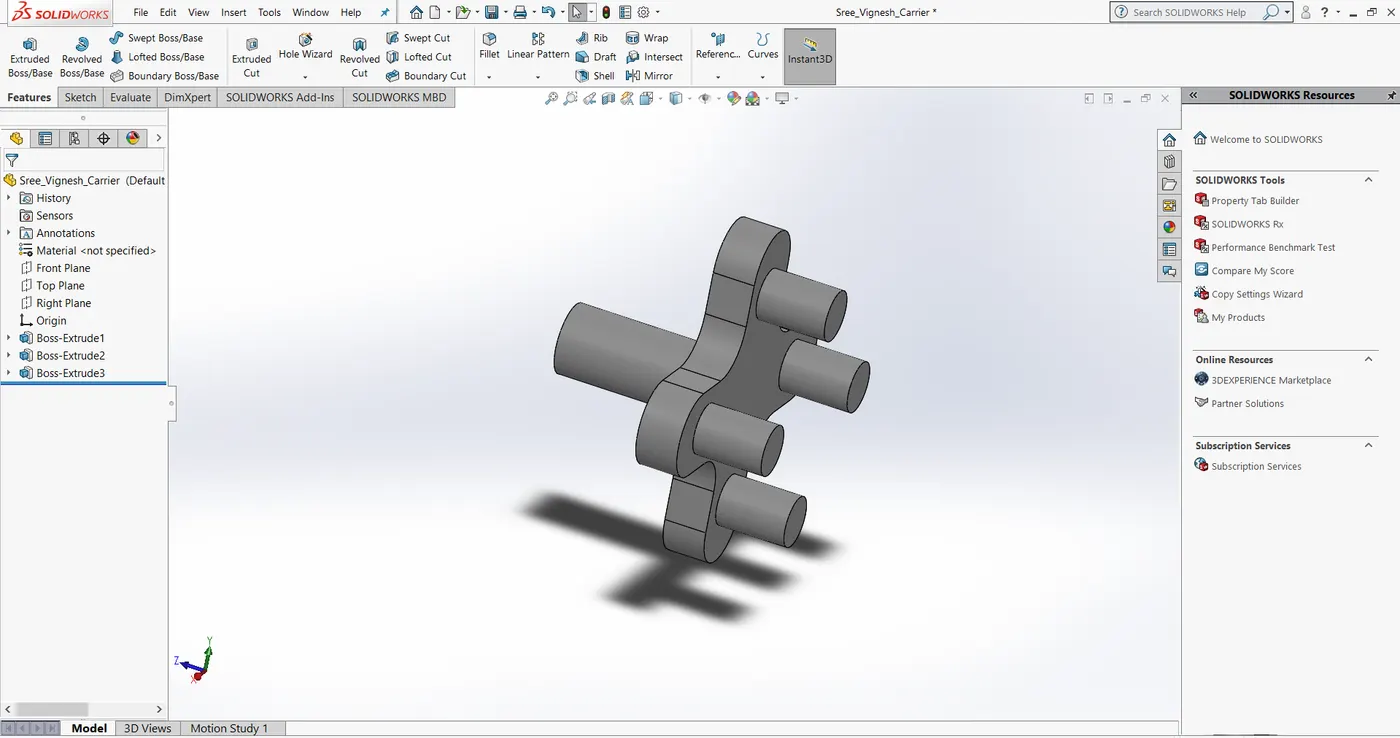
Carrier:
Assembly:
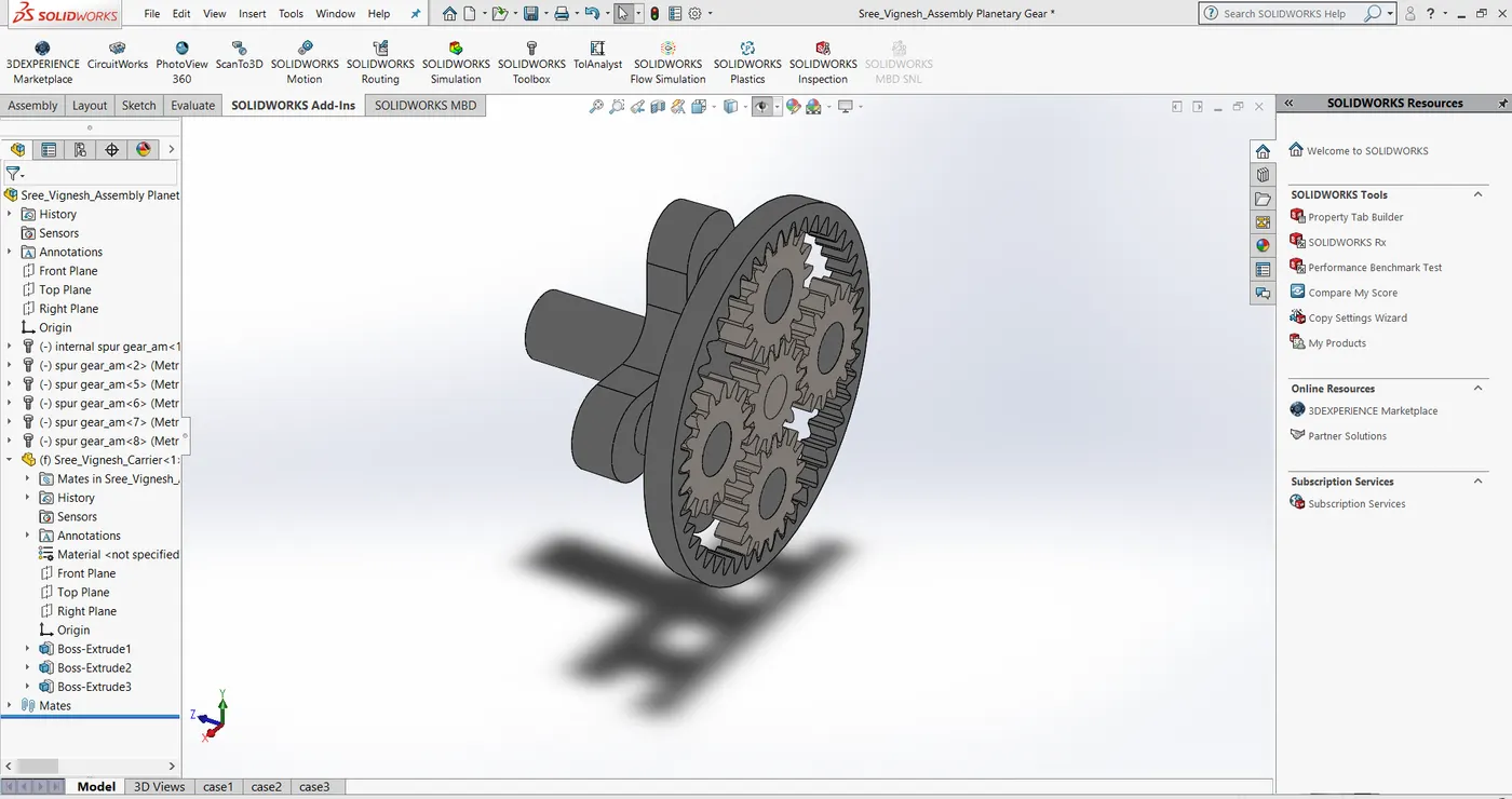
The carrier was first inserted into the Assembly environment and made to float.
It was then made coincident with the plane parallel to its face and its axis was made coincident with the other to planes in such a way that it only rotates about its axis.
After this, all the other parts were inserted and assembled using different options but Gear mate was not used.
Motion Study and setup:
The motion analysis study can be accessed by clicking on SolidWorks Motion from SolidWorks Add-ins and then clicking on Motion Study.
In order to proceed further, we should have an assembled component so that we can analyze the velocity and other desired parameters.
Rotary Motor was assigned to the Input gear at 200 RPM and according to the conditions, appropriate parts were fixed.
Solid body contacts were given and Steel (Dry) material is chosen for all the parts.
The total duration was set as for 5 seconds using the slider.
After that, Calculate is clicked to run the study. Upon completion, we can generate the results.
The input is given to the gear that is considered for Input in each case and the angular velocity output is obtained for the part that is considered as the Output in each case.
Results:
(a) Case 1:
Input - Sun gear
Output - Carrier
Fixed - Ring gear
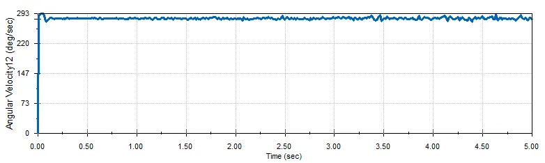
This configuration results in high torque and low speed transmission. The torque is given to the Sun gear and so angular velocity of the carrier increases. It remains almost constant through out the study with minor variations. Since the ring gear is fixed, the planet gears have to rotate about their own axis as well as slide on the ring gear.
(b) Case 2:
Input - Ring gear
Output - Carrier
Fixed - Sun gear
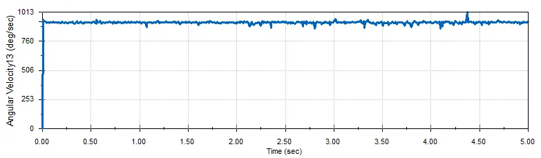
Torque is given to the Ring gear and output is obtained from the carrier. Angular velocity of the carrier increases rapidly and is the highest when compared to other two cases because the meshing of ring gear and carrier results in higher gear ratio. Therefore, this configuration gives high speed and low torque. However angular velocity remains almost constant with minor variations.
(c) Case 3:
Input - Sun gear
Output - Ring gear
Fixed - Carrier
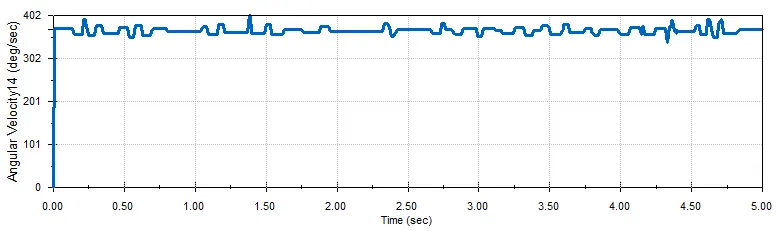
In this configuration, the torque from the sun gear is transmitted to the Ring gear by the planet gears. Since ring gear is larger in diameter as compared to planet gears, the result is low speed and high torque output.
Models and plots are provided in the link below along with Animations of the motion analysis for three cases:
https://drive.google.com/drive/folders/1PNCOq31I4KCK-hIVfsCXM2GBpLQEm8AW?usp=sharing
Observations:
By performing motion analysis on a planetary gear assembly for three different configurations, I was able to understand the variation of speed and torque.
It also gave me insights on the gear ratios that can be obtained using a single assembly, which makes this gear set a better choice in places where high efficiency is required from a compact construction.
Due to this, planetary gear has a lot of applications in the industries.
Conclusion:
Motion analysis was performed on a Planetary gear assembly for the given three conditions and the results were visualized in the form of plots. The modelling and assembly procedure, motion study and setup as well as the plots were explained in detail. A google drive link containing the models, plots and animation was also included in the report.
References:
https://gearmotions.com/fundamentals-planetary-gear-systems/
https://www.lancereal.com/planetary-gears-principles-of-operation/