Multi Body Dynamics simulation on IC Engine Valve Train
Aim:
To model, assemble and perform Motion analysis on IC engine valve train assembly using SolidWorks and obtain:
(1) Valve Lift
(2) The contact force between:
- Cam and Push Rod
- Pushrod and Rocker Arm
- Rocker Arm and Valve
And, to explain why the contact force between the Rocker arm and valve varies while measuring with respect to the X direction and measuring with respect to magnitude.
Introduction:
A valve train is a mechanical system that controls operation of the intake and exhaust valves in an IC engine. The intake valves control the flow of air/fuel mixture into the combustion chamber, while the exhaust valves control the flow of exhaust gasses out of the combusion chamber once combustion is completed.
The valvetrain consists of all the components responsible for transferring the rotational movement of the camshaft into the opening and closing of the intake and exhaust valves. Typical components are listed below in order from the crankshaft to the valves.
Camshaft:
The timing and lift profile of the valve opening events are controlled by the camshaft, through use of a carefully shaped lobe (Cam) on a rotating shaft. The camshaft is driven by the crankshaft and— in the case of a four-stroke engine— rotates at half the speed of the crankshaft.
Motion is transferred from the crankshaft to the camshaft most commonly by a rubber timing belt, a metallic timing chain or a set of gears.
Pushrod:
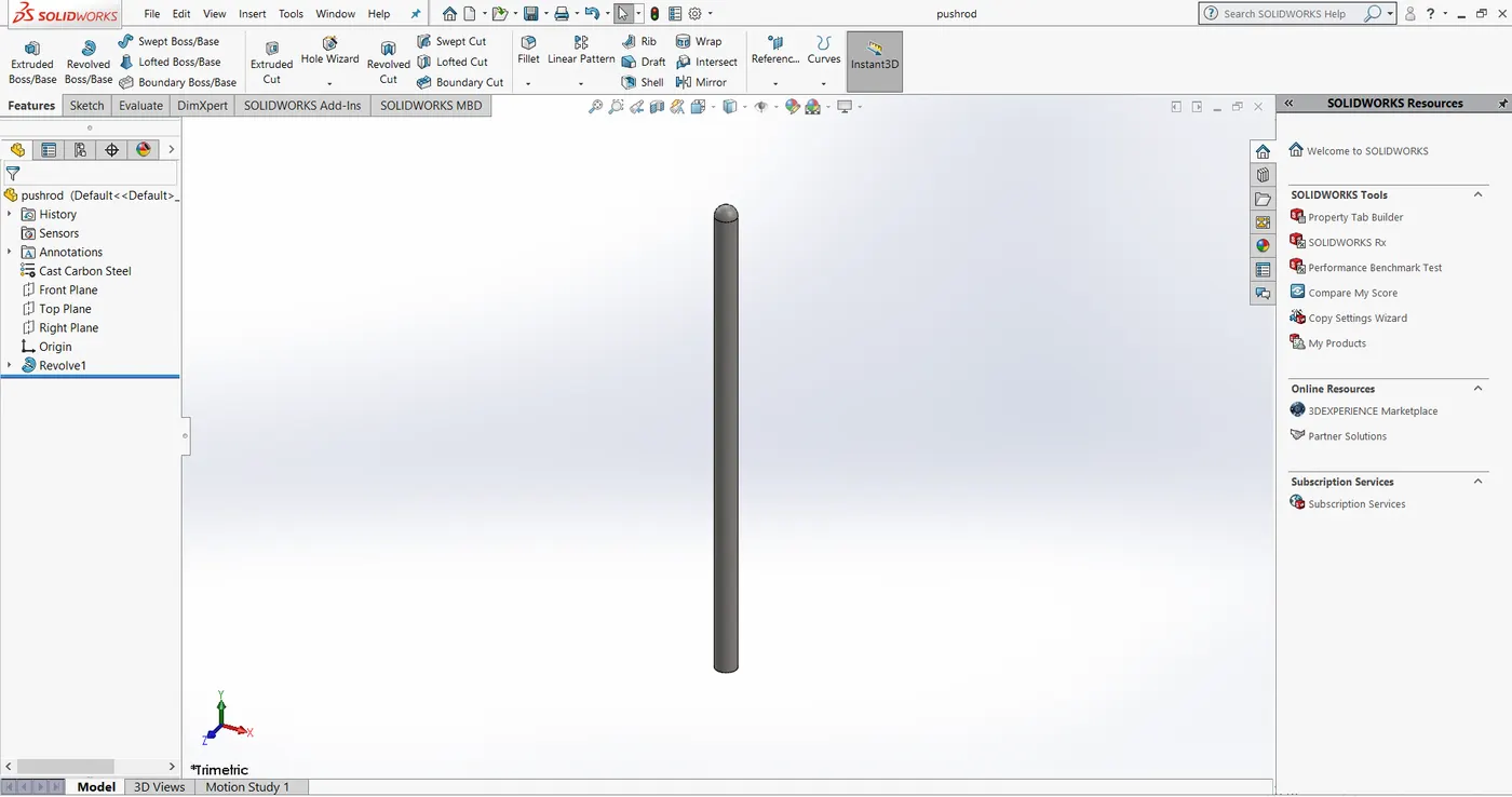
Pushrods are long, slender metal rods that are used in overhead valve engines to transfer motion from the camshaft (located in the engine block) to the valves (located in the cylinder head). The bottom end of a pushrod is fitted with a lifter, upon which the camshaft makes contact. The camshaft lobe moves the lifter upwards, which moves the pushrod. The top end of the lifter pushes on the rocker arm, which opens the valve.
Rocker Arm:
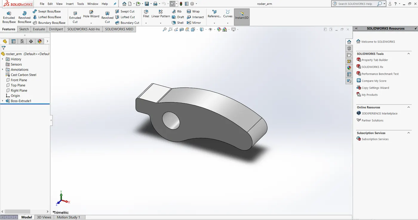
Overhead valve engines use rocker arms, which are actuated by a pushrod and pivot on a shaft or individual ball studs in order to actuate the valves.
Valves:
Most modern engines use poppet valves type, although sleeve valves, slide valves and rotary valves have also been used at times. Poppet valves are typically opened by the camshaft lobe or rocker arm, and closed by a coiled spring called a valve spring.
Procedure:
Modelling:
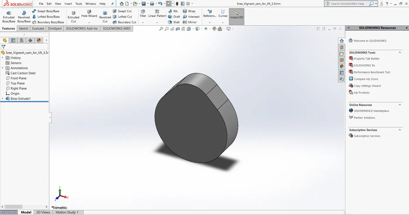
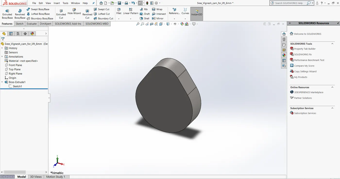
The components were modelled as per the video. However, Cam was designed with the help of the given reference document and using the formula as follows:
Given that, The diameter of lower circle (D1) is 35 mm and the diameter of upper circle (D2) is 20 mm
Since Diameters were given, the radii were obtained by dividing the diameters by 2.
Cam Lift = `(L - R1)+R2`
R1 = Radius of lower circle
R2 = Radius of upper circle
L = Distance between the two centres
Cam lift for 3.5mm:
`3.5 = (L1 - 17.5)+10`
`implies L1 = 11 mm`
L1 = Distance between the two centres for 3.5mm cam lift
Cam lift for 6mm:
`6 = (L2 - 17.5)+10`
`implies L2 = 13.5mm`
L2 = Distance between the two centres for 6mm cam lift
Other components are listed below along with the images:
Pushrod:
Rocker Arm:
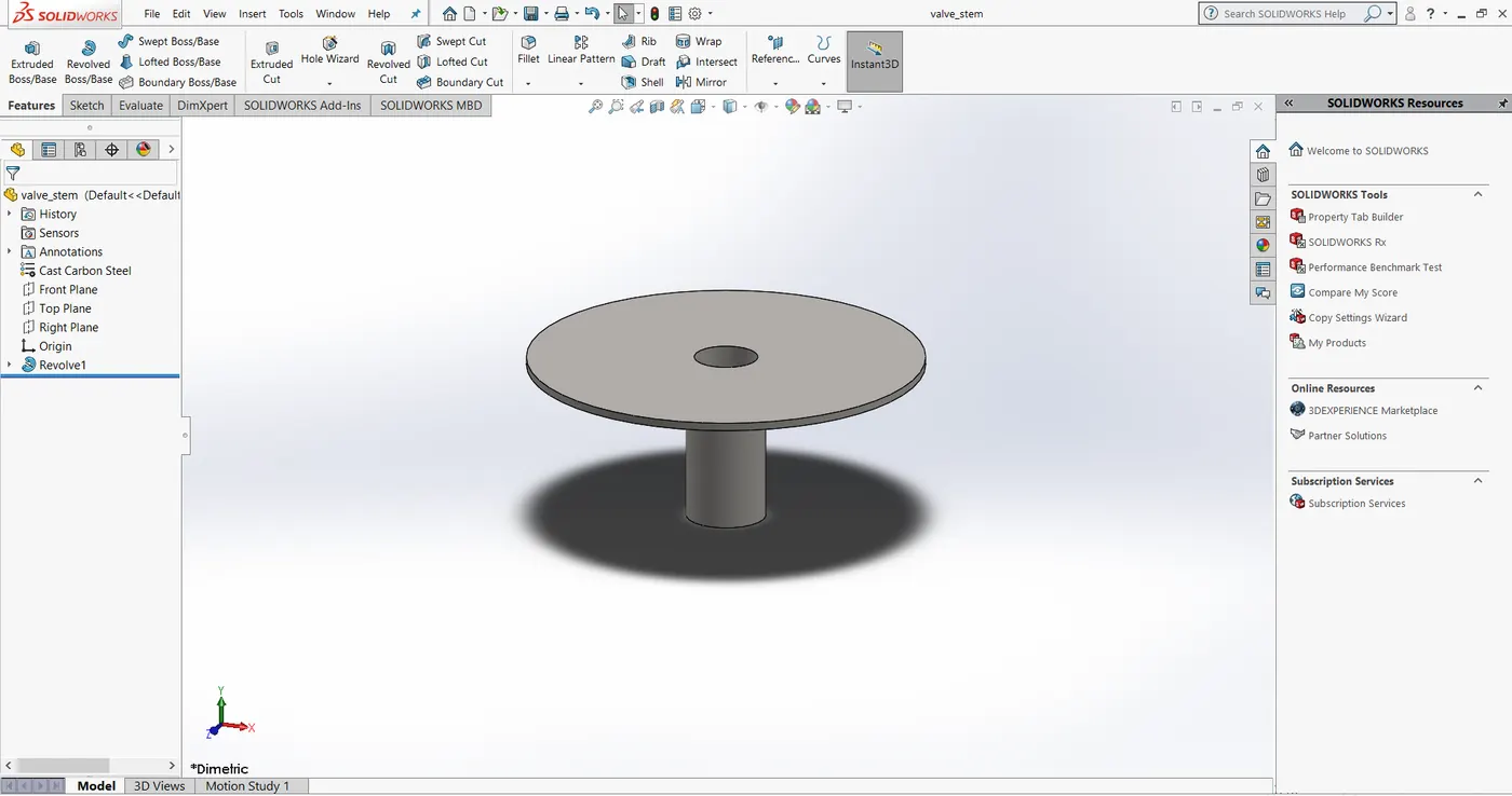
Valve stem:
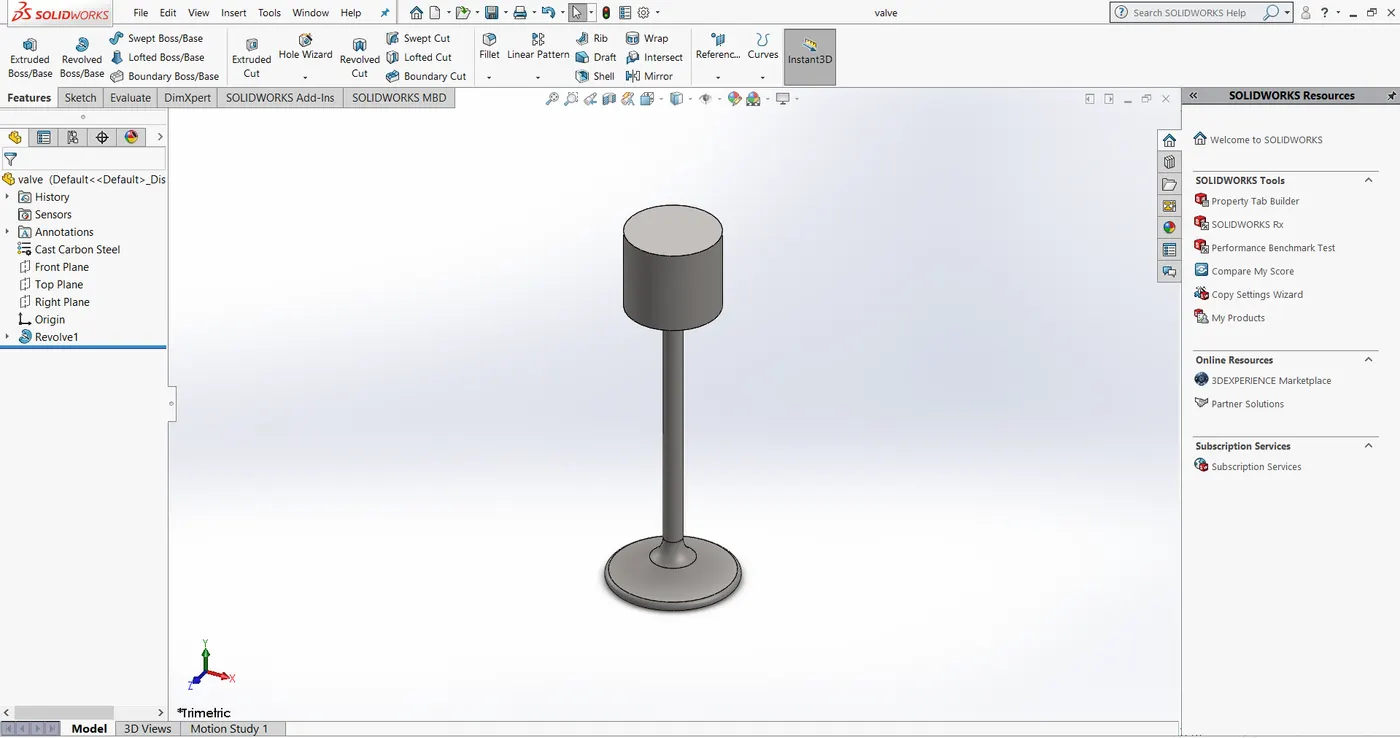
Valve:
The materials for all the components were chosen as Cast Carbon Steel.
Assembly:
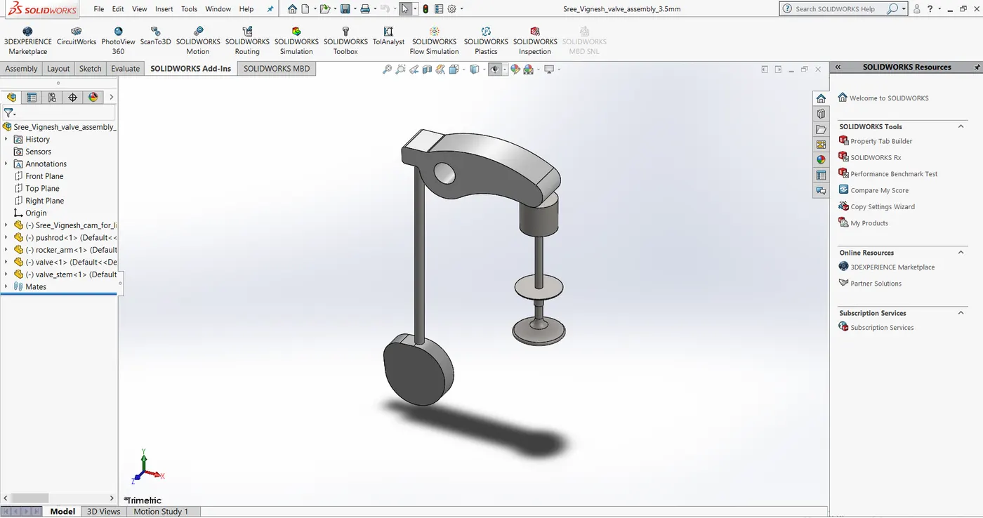
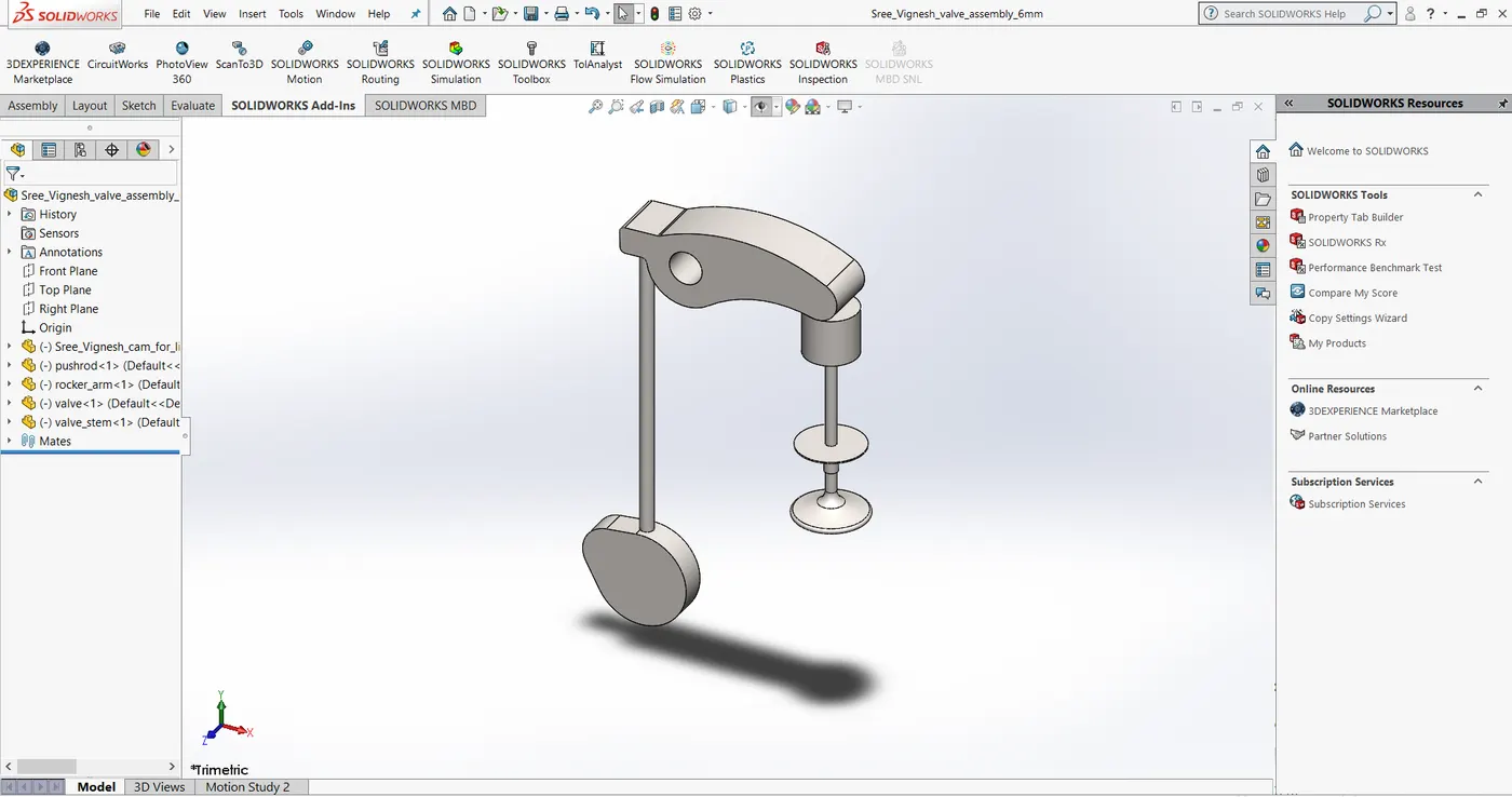
After all the components were modelled, they are assembled in Assembly environment of SolidWorks to give the desired motion.
Firstly, Cam was inserted and made to float. It was then made to coincide with the front plane and its axis with the top and right planes of the assembly (With the temporary axes made visible)
All the components were inserted one after the other and made coincident with the front plane of the assembly.
Then the axis of Valve and valve stem were made coincident. Also, distance mate was provided between the components to avoid obstruction during motion.
An angle mate of 0 degrees was given to top plane of the rocker arm and top plane of the assembly so that they remain parallel all the time.
Assembly for Cam lift 3.5mm:
Assembly for Cam lift 6mm:
Motion Study and Setup:
The motion analysis study can be accessed by clicking on SolidWorks Motion from SolidWorks Add-ins and then clicking on Motion Study.
In order to proceed further, we should have an assembled component so that we can analyze the desired parameters.
The material is Cast Carbon Steel for all the components.
The Motion Study was run for the following two cases:
|
S.No. |
Cam Lift(mm) |
Speed(RPM) |
Material |
|
1 |
3.5 |
1500 |
Cast Carbon Steel |
|
2 |
6 |
1500 |
Cast Carbon Steel |
For both the cases, a Rotary Motor with speed of 1500 RPM was assigned to the Cam axis.
Solid Body Contacts were given between each and every part of the assembly.
A linear spring with stiffness of 15 N/mm was assigned between upper end of valve stem and lower stem of the valve.
For accurate results and smooth animation, 9000 fps was chosen since RPM is 1500.
Results:
- Cam lift 3.5mm:
(a) Linear Displacement of the valve:
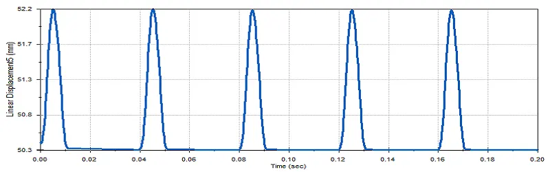
The linear displacement plot indicates the movement of the valve through the entire motion. The pattern of displacement variation is constant since the motion of Valve is up and down.
The maximum position of the valve from the above is 52.22mm and the minimum is 50.37mm. Hence the Valve lift is the difference of the two values, which is found to be 1.85mm
(b) Contact force between the Cam and Push Rod:
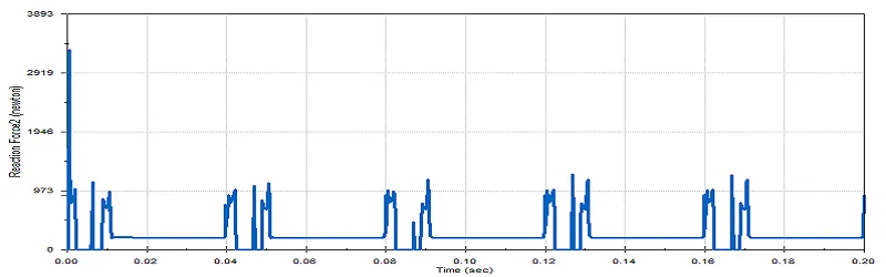
From the above plot, we can see that the force initially reaches a higher value which indicates the sudden contact between the two components. After that, the pattern is same with ups and downs. Maximum value of force in this case is around 1300N.
(c) Contact force between the Push Rod and Rocker arm:
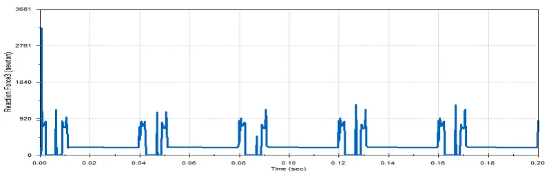
From the above plot, we can see that the force initially reaches a higher value which indicates the sudden contact between the two components. After that, the pattern is same with ups and downs. Maximum value of force in this case is lower than the previous one.
(d) Contact force between the Rocker arm and Valve:
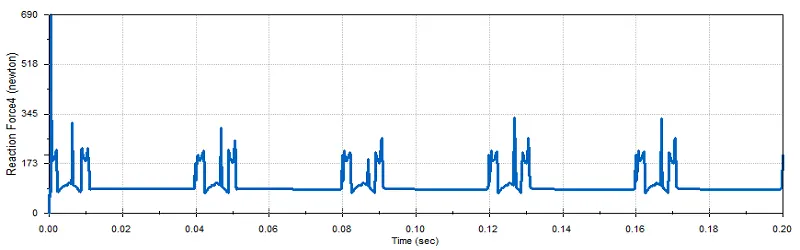
From the above plot, we can see that the force initially reaches a higher value which indicates the sudden contact between the two components. After that, the pattern is same with ups and downs. Maximum value of force in this case is the lowest and is around 330N to 340N.
- Cam lift 6mm:
(a) Linear Displacement of the valve:
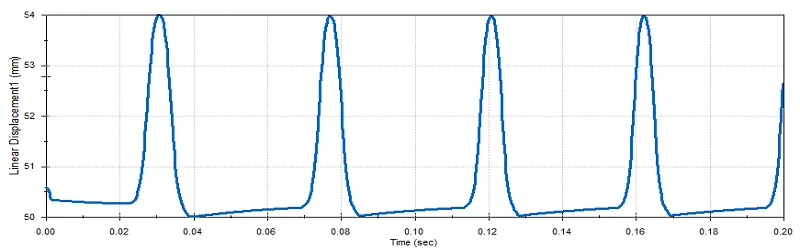
The linear displacement plot indicates the movement of the valve through the entire motion. The pattern of displacement variation is constant since the motion of Valve is up and down.
The maximum position of the valve from the above is 53.82mm and the minimum is 50.25mm. Hence the Valve lift is the difference of the two values, which is found to be 3.57mm
(b) Contact force between the Cam and Push Rod:
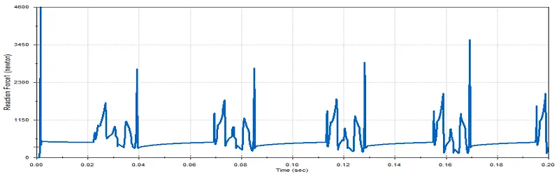
From the above plot, we can see that the force initially reaches a higher value which indicates the sudden contact between the two components. After that, the pattern is same with ups and downs. Maximum value of force in this case is around 3500N.
(c) Contact force between the Push Rod and Rocker arm:
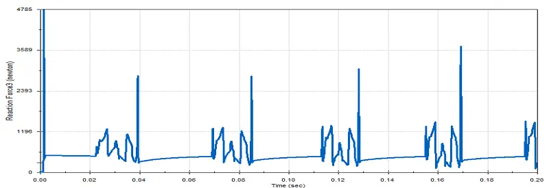
From the above plot, we can see that the force initially reaches a higher value which indicates the sudden contact between the two components. After that, the pattern is same with ups and downs. Maximum value of force in this case is around 3600N.
(d) Contact force between the Rocker arm and Valve:
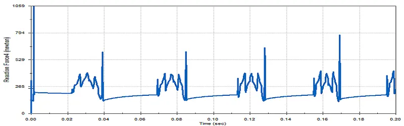
From the above plot, we can see that the force initially reaches a higher value which indicates the sudden contact between the two components. After that, the pattern is same with ups and downs. Maximum value of force in this case is the lowest and is around 750N to 800N.
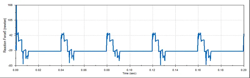
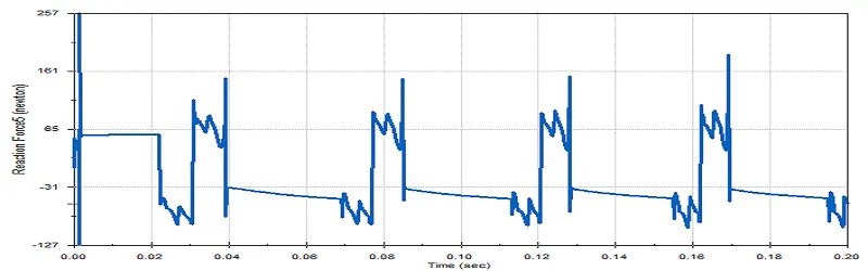
Explanation for why the contact force between the Rocker arm and valve varies while measuring with respect to the X direction and measuring with respect to magnitude:
- The contact force between the Rocker arm and valve varies while measuring with respect to the X direction and measuring with respect to magnitude because the line of action of contact force is varying continuously.
- Along the X direction, the surfaces come in direct contact with each other creating friction. This can be seen in both positive and negative axes from the plot below. Due to this frictional force, there are losses and so the value is lesser.
- In case of magnitude, the value is the sum of forces in all three directions and so it is greater than the measurement with respect to X-direction.
(a) Comparison for Cam lift 3.5mm:
Measurement with respect to magnitude:
Measurement with respect to X-direction:
(b) Comparison for Cam lift 6mm:
Measurement with respect to magnitude:
Measurement with respect to X-direction:
The animation for both the cases is found in the link below:
https://drive.google.com/drive/folders/1zC-tgNuKms3qjAtcislOS9IG5yNaMhbF?usp=sharing
Observations:
The valve lift is 1.85mm when the lift of the Cam is designed to be 3.5mm
The valve lift is 3.57mm when the lift of the Cam is designed to be 6mm
The contact force is higher between Rocker Arm and Valve when measured with respect to Magnitude than when measured with respect to X-direction, since frictional losses are considered when measured along X-direction.
Conclusion:
Motion Study on an IC Engine Valve Train was carried out and the results were visualized in the form of plots. Detailed explanation was given for modelling and assembly procedure as well as for the plots obtained. Also, explanation for why the contact force between the Rocker arm and valve varies while measuring with respect to the X direction and measuring with respect to magnitude was also given in the report.
Reference: