Multi Body Dynamics simulation on IC Engine Piston Assembly
Aim:
To model the components of a IC engine piston assembly, assemble and perform motion analysis study on the assembly using SolidWorks Motion Analysis.
Introduction:
The Internal Combustion engine (ICE) is a heat engine in which the combustion of a fuel takes place inside the combustion chamber. The expansion of high temperature and high pressure gases produced by combustion applies some force on a component called the piston, which then reciprocates inside the combustion chamber (top to bottom/ bottom to top) and transfers this chemical energy into useful work. IC engines are usually powered using energy-dense fuels such as Gasoline, Diesel etc obtained from fossil fuels.
The components of a piston assembly are explained as follows:
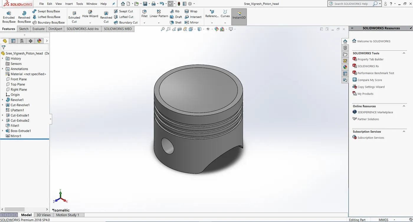
Piston is a cylindrical component fitted into the cylinder of an engine and forms the moving boundary of the combustion system. This is also the first link in transmitting gas forces to the output shaft.
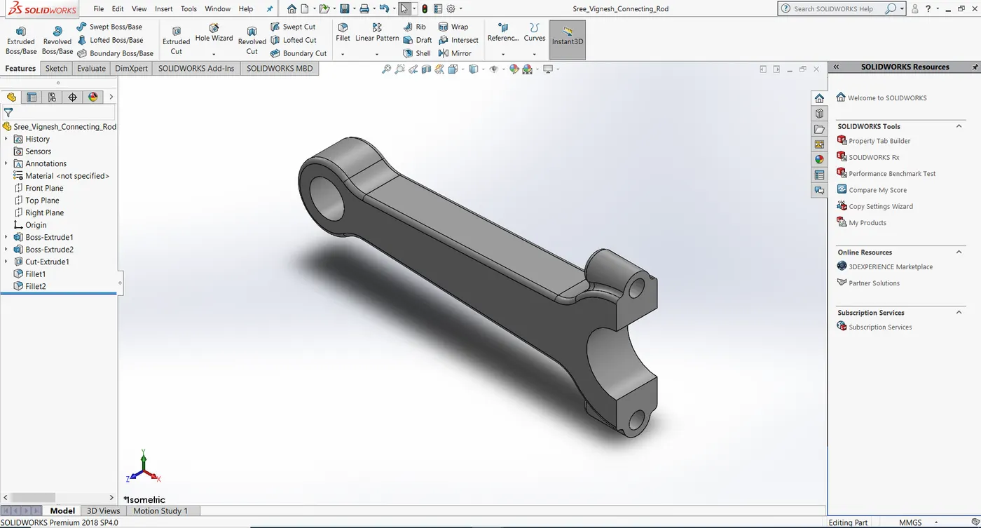
Connecting rod interconnects the piston and the crankshaft and transmits gas forces from piston to the crankshaft. The two ends of the connecting rod are called small end and the big end. Small end is connected to the piston by Gudgeon pin (wrist pin) and the big end is connected to the crankshaft by crankpin.
The output power is taken from the crankshaft which converts the reciprocating motion of the piston into useful rotary motion of the output shaft.
This assembly of piston, connecting rod and the crankshaft forms the essential part of an ICE in transferring chemical energy into useful work as a result of combustion.
Most ICEs are used in mobile applications and are the dominant power supply for vehicles such as cars, aircraft, and boats.
Procedure:
- Modeling:
The piston, gudgeon pin, connecting rod and crank are modelled as per the dimensions.
(a)Piston:
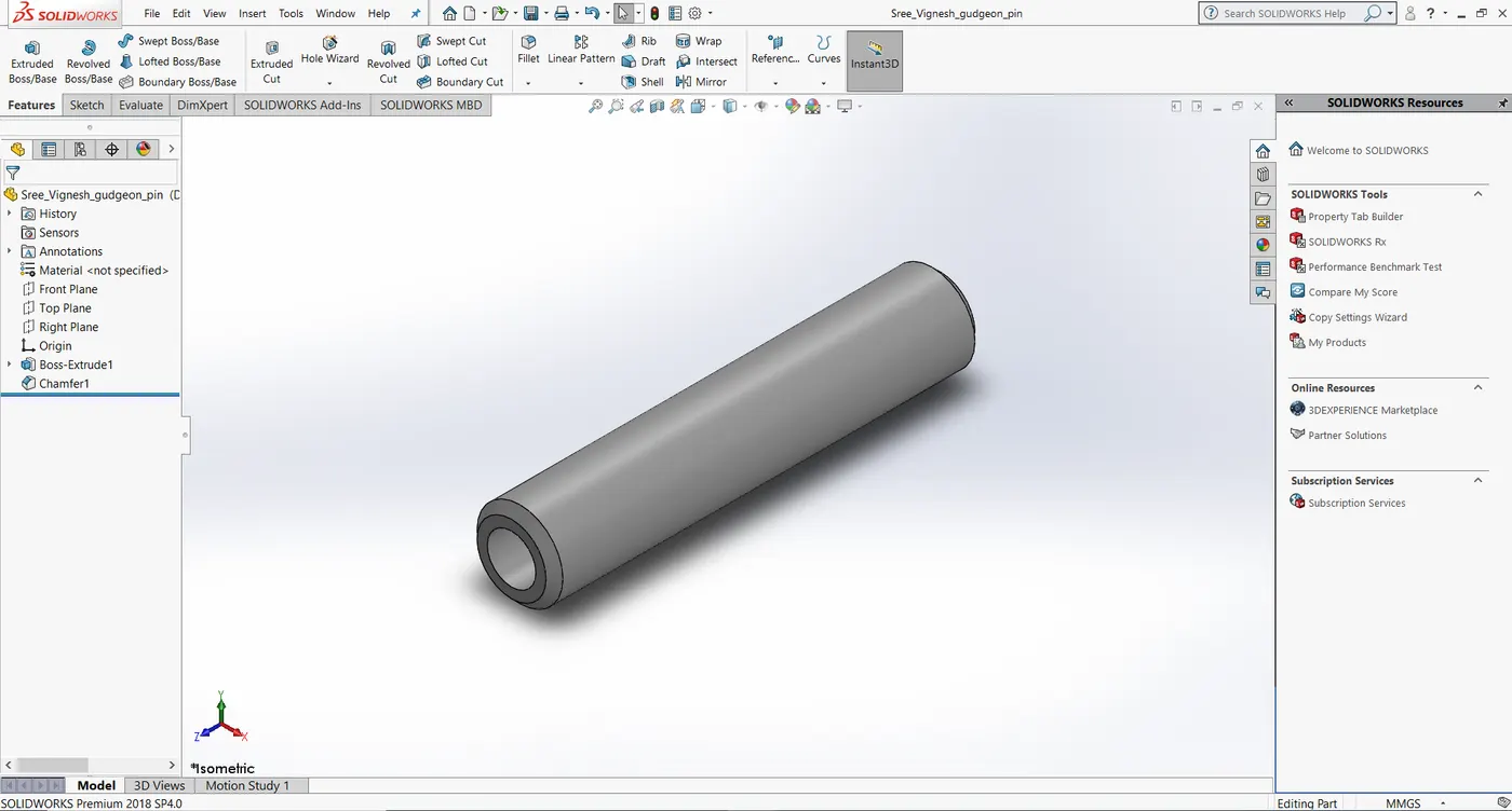
(b)Wrist pin (or) Gudgeon pin:
(c)Connecting rod:
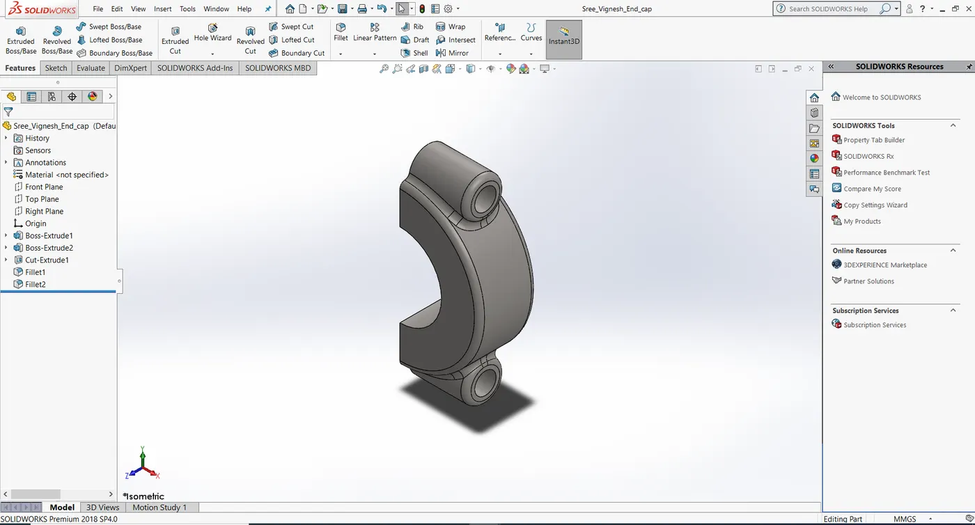
(d)Connecting rod end cap:
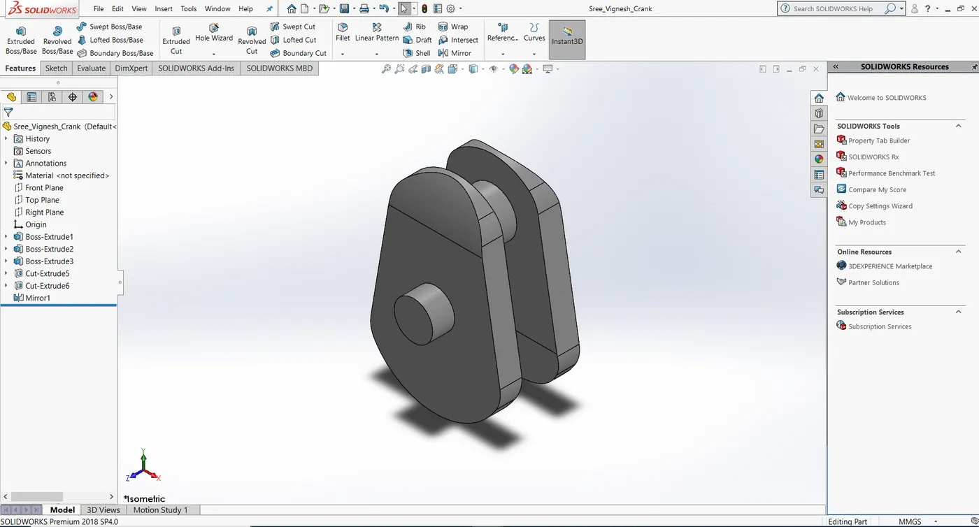
(e)Crank:
- Assembly:
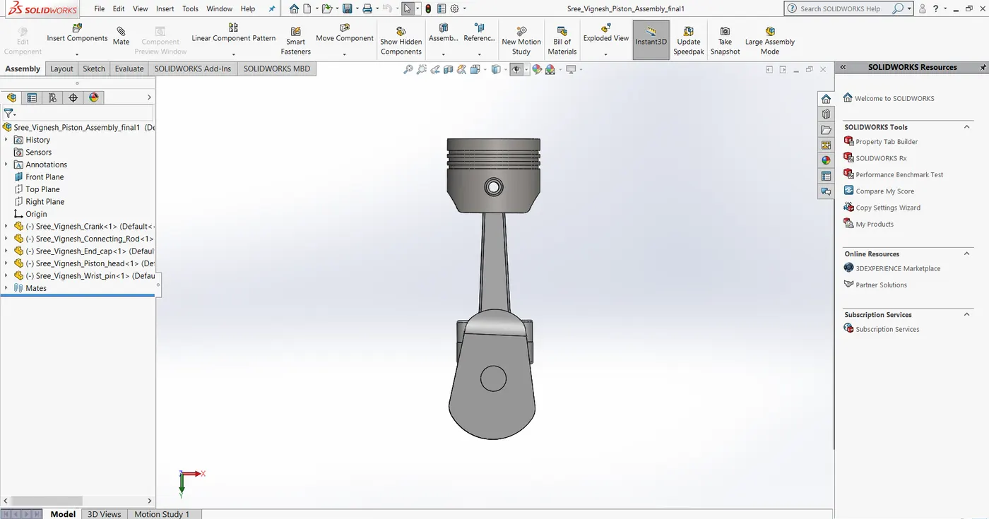
After modelling, the components were assembled in the assembly environment of SolidWorks.
First, the crank was opened and then made to float. Its axis was made to coincide with top and right plane of the assembly while its front plane was fixed at a distance from the front plane of the assembly.
Next, connecting rod and end cap were opened and then their axes as well as faces were made to coincide so that they move as a single component.
After that, the crank was inserted and made to coincide with the axis of connecting rod. The crank and connecting rod were then provided a distance mate of 1 mm as a clearance between the two components.
Finally the Piston and gudgeon pin (or) the wrist pin were inserted and assembled in such a way that they move as a single component. This was done by making coicident with respective axes and planes.
Then the wrist pin axis and connecting rod axis are made coincident and front plane of connecting rod with front plane of the piston and then the right plane of the piston with the right plane of the assembly.
(a) Assembly with wrist pin offset = 0 mm:
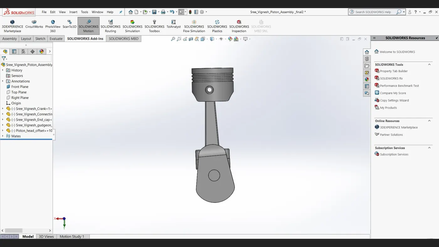
(b) Assembly with wrist pin offset = +10 mm:
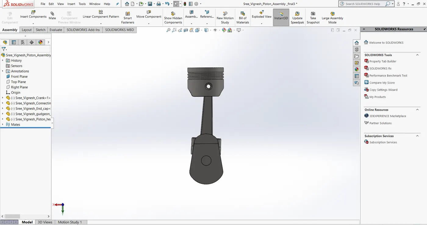
(c) Assembly with wrist pin offset = -10 mm:
Motion study and setup:
The motion analysis study can be accessed by clicking on SolidWorks Motion from SolidWorks Add-ins and then clicking on Motion Study.
In order to proceed further, we should have an assembled component so that we can analyze the linear displacement and other desired parameters.
Motion study is performed for the following three cases:
|
S.No |
Wrist Pin Offset ` |
Crank Speed (Rpm) |
|
1 |
0 mm |
2000 |
|
2 |
10 mm Positive |
2000 |
|
3 |
10 mm Negative |
2000 |
For all these cases, a rotary motor was assigned to the axis of the crank at 2000 rpm clockwise (with the temporary axes made visible).
Solid body contacts were provided for every set of components separately and Steel (Dry) material was chosen for all the components.
Gravity was enabled and acts in downward direction. 12000 fps was set, since the rpm is 2000 and this was done to obtain a smooth motion and accurate results from the simulation.
After that, Calculate was clicked to run the study. Upon completion, the results were generated.
Using 'Export to Spreadsheets' option from the Results drop down menu, the values from the study results were exported to MS-Excel and further tasks were performed as given.
Results:
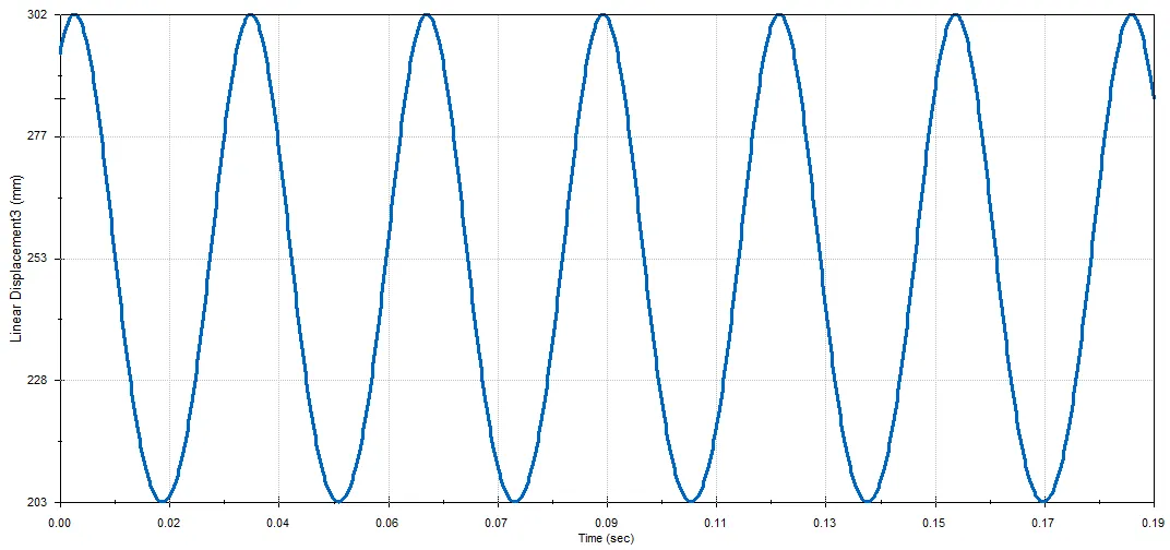
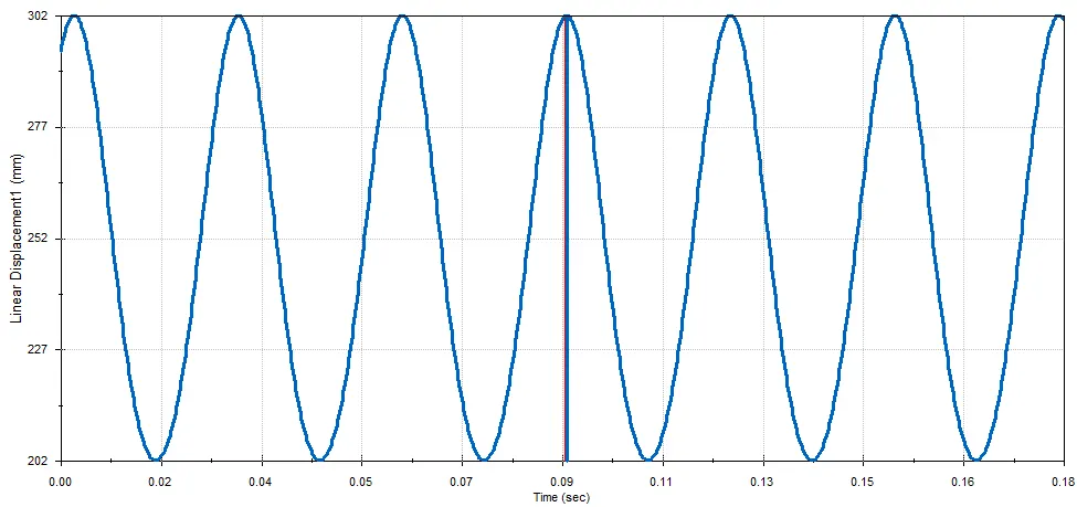
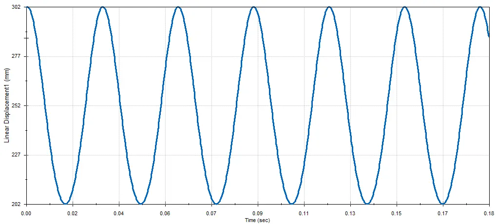
The following plots were obtained for Linear Displacement vs Time in each of the three cases:
(a) Case 1 - Wrist pin offset = 0 mm:
(b) Case 2 - Wrist pin offset = +10 mm:
(c) Case 3 - Wrist pin offset = -10 mm:
(d) Superimposed graphs obtained from Excel:
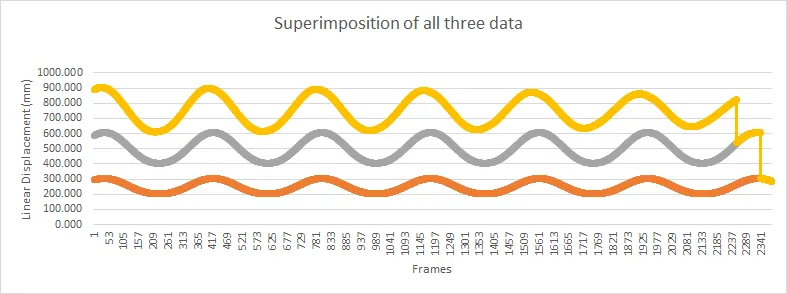
Three different colors indicate the three different data exported to excel from SolidWorks and this plot was obtained by superimposing all these data.
The animation for all three cases can be found in the link below:
https://drive.google.com/drive/folders/1o7JL-AGm7oDHL7SMSytW17TUsVmbCFHa?usp=sharing
Explanation and observations:
When the crank angle is at 0° and at time as 0 second, the piston is at Top Dead Centre (TDC) and the displacement reaches the maximum value.
After half rotation, the angle is 180° and the piston is at Bottom Dead Centre (BDC) and the displacement reaches the minimum value taking a sine wave path.
The angular velocity of crank almost remains constant throughout the motion in all the three cases.
The displacement amplitude for the plot with 0 mm Offset is 302.499 mm and is maximum as compared to +10 mm offset (302.3094 mm) and -10mm offset (302.3090 mm) which is the least in all three cases. This is because the piston displacement decreases as it has to travel a less distance from TDC to BDC because of the wrist pin offset.
When the wrist pin is in the centre of the piston (i.e. no offset), the connecting rod is straight and the reciprocating motion places huge load, which the crank has to bear. This leads to a loss of both power and speed from the engine.
With an offset pin, the connecting rod is not exactly straight at TDC. This allows the crank to rotate with much less resistance giving the engine more power and speed compared to crank movement with no offset of the wrist pin.
Conclusion:
The parts of IC engine piston assembly were modelled, assembled and motion analysis was performed. The results were visualized in the form of plots for linear displacement of the piston and explanation for modelling, assembly as well as the results was included. Also, a detailed explanation on the Motion study setup and observations made from the study was given on the report.