Modelling of 25 storey building with the specified properties using ETABS
Structural Element Sizes
- Beams : 300 × 400 mm
- Columns : 800 × 800 mm
- Slab : 150 mm thick
Material Properties
- Grade of Concrete : M30
- Grade of Steel Reinforcement Bars : Fe 415
Loading
- Dead Load on beams from infill wall : 10 kN/m (Let us assume the same for roof floor in view of parapet)
- Live load on floor : 3 kN/m2 (Let us assume the same for roof floor)
a) Buildings are assumed to be pinned at the base
b) All columns in all storey are of the same size
c) All beams in all storeys are of the same size
d) Building is located on Soil type-II and in Zone-III. Assume other factors if required.
- Open the ETABS software.
- Click the Filemenu and select the Create New Model option.
- Selectinga new model brings up the Initialize Model dialog box.
- Select the Built-in Settings option and select Display Units and Codes.
- After model initialization, select Grid and Story inputs from the New Quick Model Template dialog box.
- In this dialog, select the grid spacing and custom story data that will be used to provide the inputs specified above.
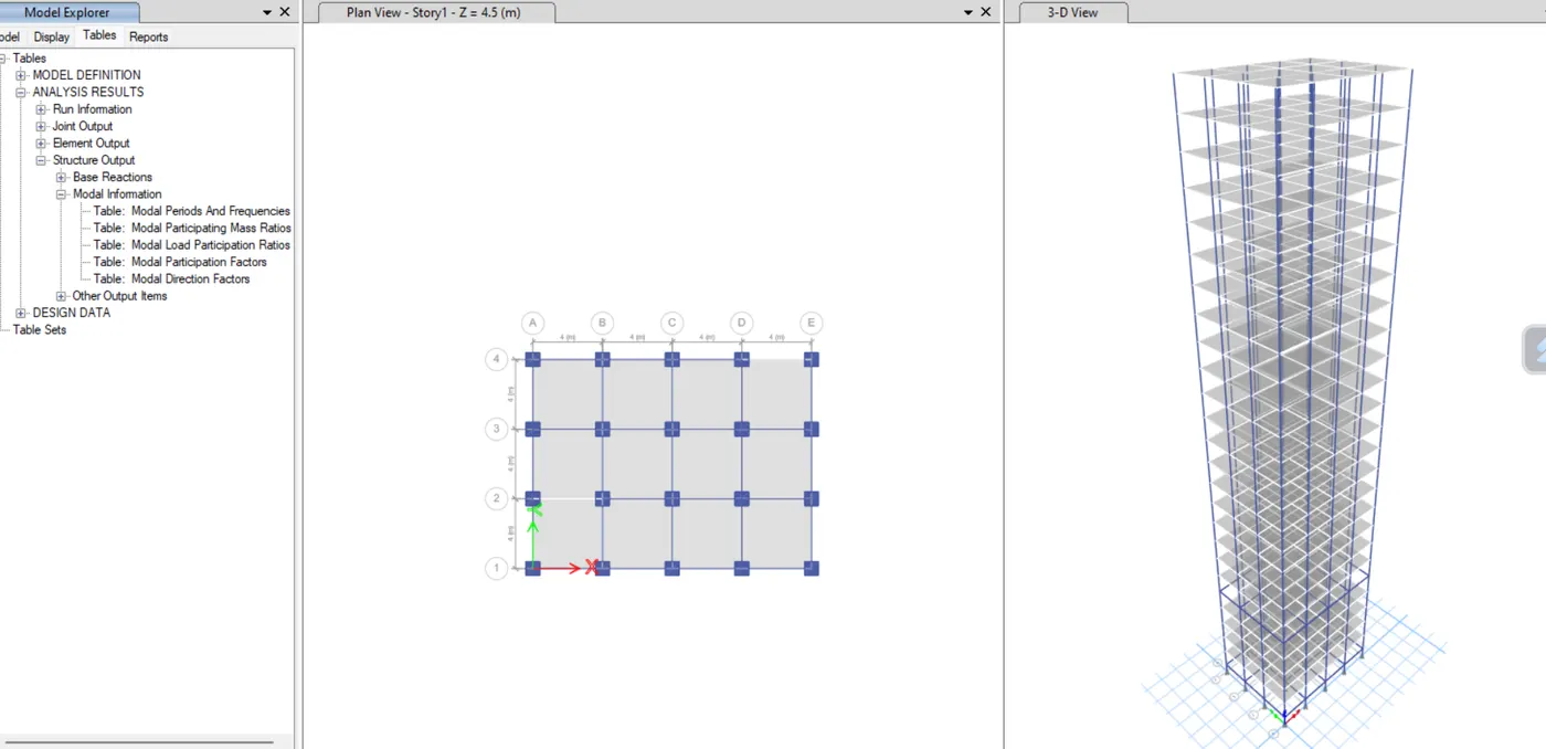
- Enter X raster data is 4 meters away, Y raster data is 4 at 4 meters distance.
- Editing a floor with a user-defined floor input will include 26 floors (1.5m high pedestal + 25 floors of 3m height each). Floor 1 is labeled as the main floor and all levels above it are similarly labeled.
- On the Define tab, select Material Properties.
- Define material of concrete grade M30 and steel for transverse stiffeners as grade 415 and longitudinal stiffeners as grade 500.
- On the Define tab, select Section Properties.
- Click on the Frame section and create a new property as Beam and enter the values as 300 x 400 mm.
- And similarly create column and slab properties of 800x800 of column and slab of thickness 150mm.
- We added a plate size of 150mm to the list, taking advantage of the properties of the membrane. Membrane properties help the structural analysis to consider only the plate weight and floor weight, but the stiffness component of the flange advantage is not considered during the calculation.
- Then, using the Quick Draw Tool, draw 800x800mm columns at the intersections of the horizontal and vertical grids and bars, leaving all floors as they are.
- Similarly beams are also drawn using quick draw beams.
- And the slabs are also drawn using the quick draw option and clicking on individual grid.
- Select Assign and click Joints Select fixed supports.
- Attach the pin support to the base.
- Next, define the load pattern. Click the Define tab, then click Load Patterns.
- Defines loads such as dead load, live load, brick load, seismic load in x direction, positive x and negative x, and equal load in y direction. State the IS code for each load.
- Click Change Side Load, set the range from Base to Floor 25, set the Seismic Zone Factor to 0.36, Importance Factor to 1.25, and Period to 0.5 seconds.
- Do the same for all seismic loads.
- Match loads and select similar floors.
- On the Assign tab, click Load Shell. Click on thepayload and enter the value as 3kn/m^2.
- Click Apply.
- For the roof we will take only 50% of the live load.
- Similarly, add a payload of 10 kn/m^2 to all supports.
- To do this, select all beams from the selected beam object type.
- Go to Frame Loads, click Distributed Loads and enter the value as 10 Kn/m^2.
- Then go to Mass Source on the Definition tab. Change the mass source and mark the desired load.
- Add a load pattern and assign it to the model.
- Define the load case.
- Click on the load combination.
- Click on the combination to add the standard them.
- Now create the diaphragm by going to the assign tab then shell and select diaphragms
- Analyze the model using analyze option then click on check model, the modelled structure is verified without errors and warnings.
- The model is analyzed using Analyze > Run Analysis to logically cross-check the deflection pattern, BMD/SFD pattern. It is understood that the processed model provides reliable results.
-
Result: -
Criteria
Desirable solution
Exercise result
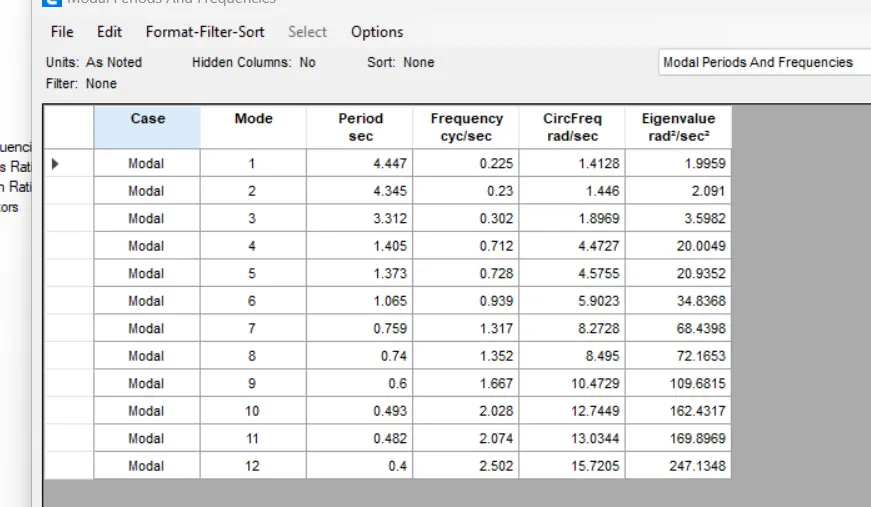
Fundamental Translational Natural period
x- direction
4.4 seconds
4.22
y-direction
4.2 seconds
4.04
Tortional irregularity
IS 1893-2016(part-1) Table-5
Tortional mode time period should be lesser than X and Y direction time periods
Yes (3.18)
Vertical irregularity
IS 1893-2016(part-1) Table-6 clause-7
First three modes together should contribute at least 65% in mass participation factor in each principal direction.
Yes (1st & 2nd modes contribute 80% of the mass itself)
Fundamental lateral natural periods in two principal plane directions are away from each other by at least 10%
No (if calculated according to the code the value should be 3.8 but the value is 4.04)
Inter-storey Drift
IS 1893-2016(part-1) clause-7.11.1.1
Storey drift shall not exceed 0.004 times the storey height for base shear with no load factors (4x10⁻³)
(0.004x73.5=0.294)
The max storey drift is 0.0017 so it satisfies the clause-7.11.1.1
- The tables for the checks of translational fundamental natural time period can be obtained from the display tab>show tables then a dialogue box will; appear. Select analysis result>structure output> modal information> modal periods and frequencies/ modal participating mass ratios.
- And the storey drift chart can be obtained from display>storey response plot>select eqx/eqy from the case/combo drop down.