Modelling of 25 storey building with the specified properties using ETABS
Aim:-To model and Analyse 25 storey building with given specifications and to cross check the parameters as per is 1893 provisions.
Given data:
Materials used :- Concrete M30 grade
Reber- Fe415 steel
Frame sections
Beam -400mm*300 mm
Column-800mm*800 mm
Slab – 150 mm thick
Loads
Live load -3kN/m^2
Masonary infill-10 kN/m^2
Procedure :-
1.How to create the model
- Open Etabs software go to file menu and choose to create a new model option.
- After choosing a new model a dialogue box will appear as model initialization.
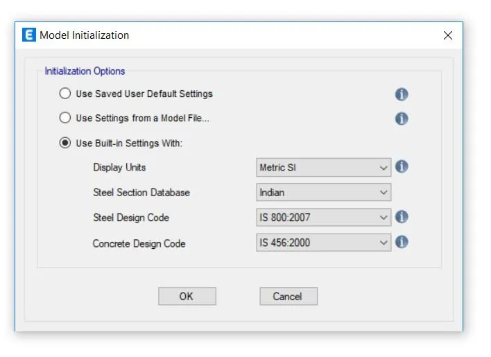
- choose the built in setting option and select the display units and codes.
- after model intiialization select the grid and story inputs from the new model quick templataes dialogue box.
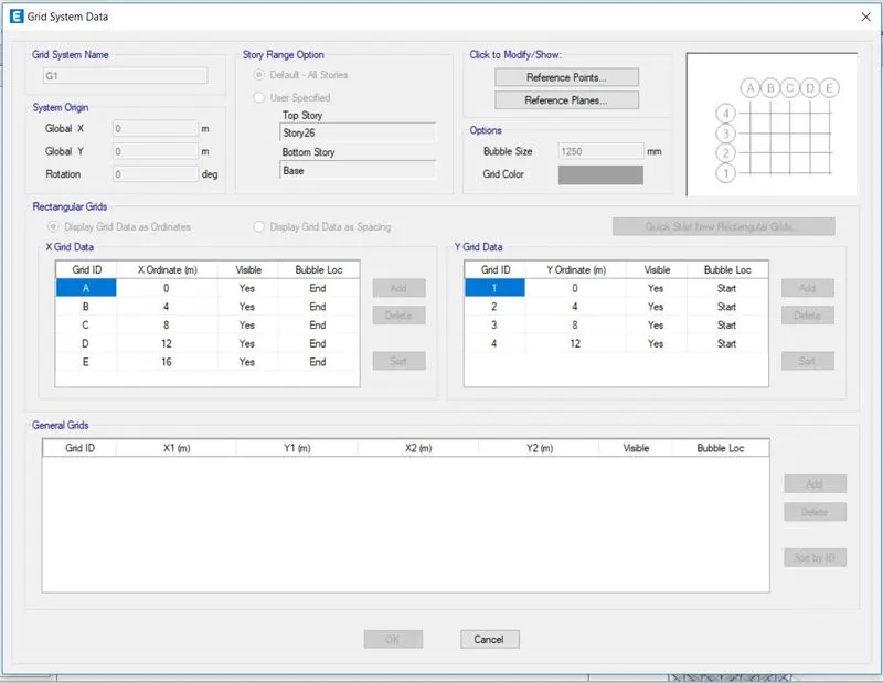
- in this dialogue box choose the grid spacing and custom story data which is used to provide the inputs specified above.
- enter X grid data at a distance 5 m and Y grid data at a distance 4 m.
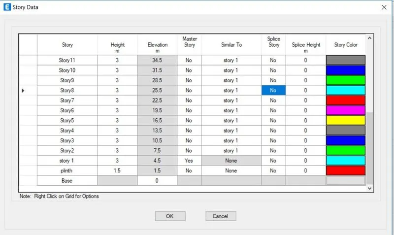
- now edit the stories by using the user defined storey inpput 26 storeys are incorporated (plinth at 1.5 m from base +v25 storeys at a distance of 3 m each)
storey 1 can be lebelled as master storey and all the other storey can be labelled as similar to that
2. Defining the material properties
- In the next step we have to define the material properties for this go to define tab and define the materials
- define the materials of concrete M30 grade and steel of Fe415.
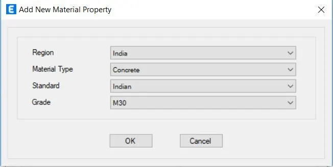
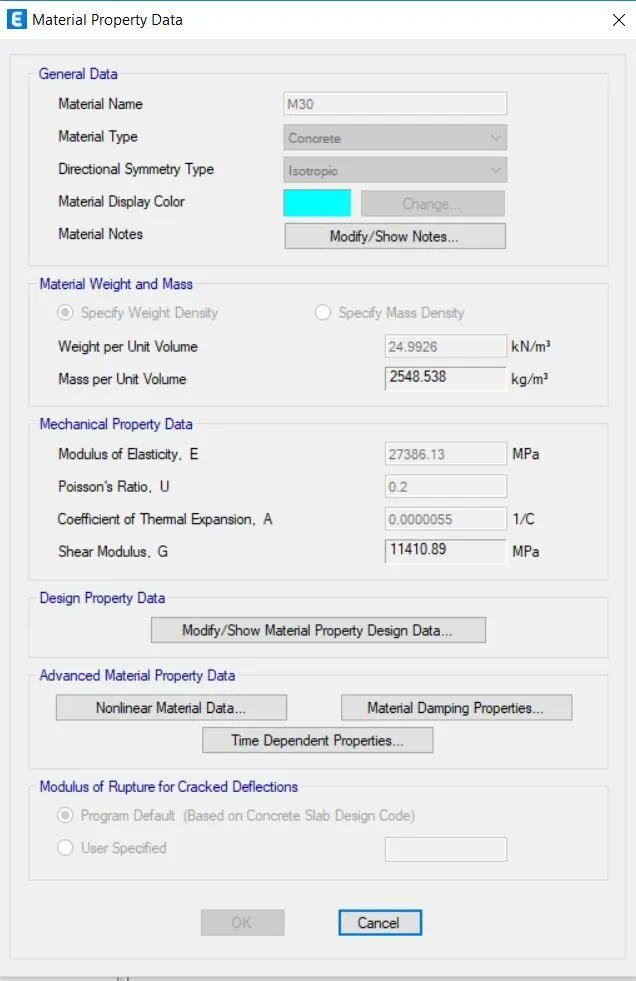
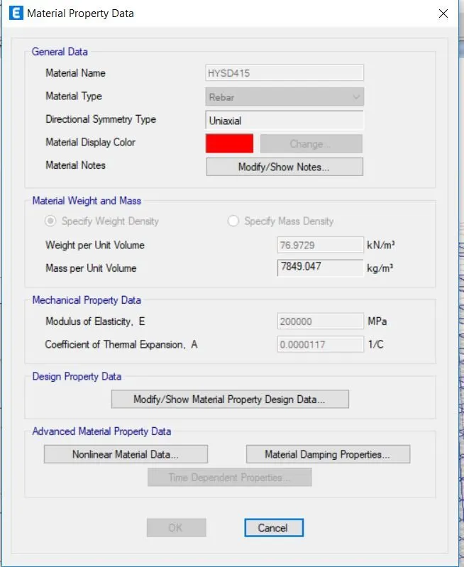
3. Now we have to define the Frame sections
- To define the beam section go to define tab select the frame sections
- Create a new property Beam and input the values as 300x400mm
- modify the property and click as m3 design only. and provide cleaar cover as 60 mm.
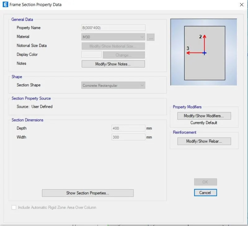
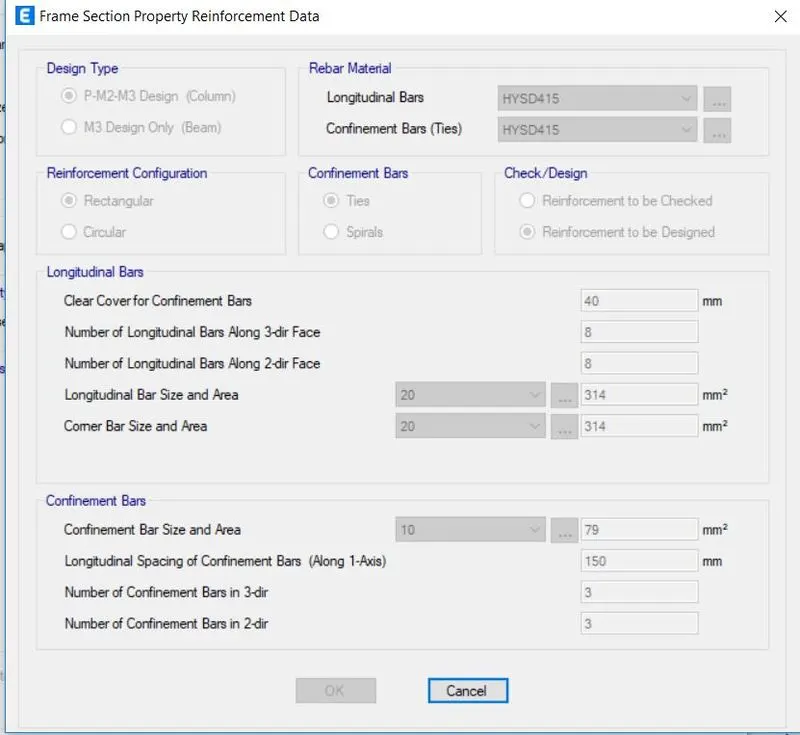
- Add new property and define as column
- input the column dimensions as 800 x 800
- in the property modifier click as P (2 and 3) design.
- then check the Reinforcement needs to be designed box
- add the number of bars as 8 in both the directions
- add the cover as 40 mm.
4.In the nect step Slab needs to be defined
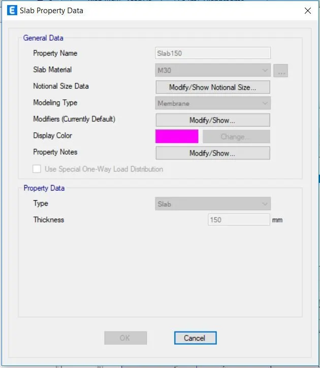
- go to define tab click on section properties and then click on slab sections
- click on the membrane and then add the thickness of the slab as 150 mm and click on the m 30 d
5. Drawing frame and slab sections section.
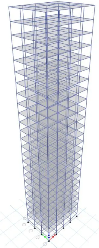
- now using the quick draw command draw all the columns and beams.
- similary draw the slab sections.
5. Defining the loads
- go to define tab and click on the load patterrns .
- click on add new load
- add masonary infill loads as super dead loads
- live loads and earth quaake loads .
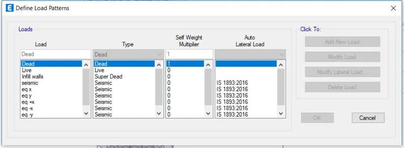
click on the modify lateral lods
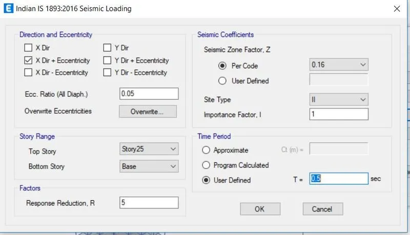
- select the sesimic zone factore as 0.16 soil type as II Importance factor as 1 and Time period as 0.5 sec and reduction factore as 1
5. Assigning the loads
- select the frames and then go to Assign tab.
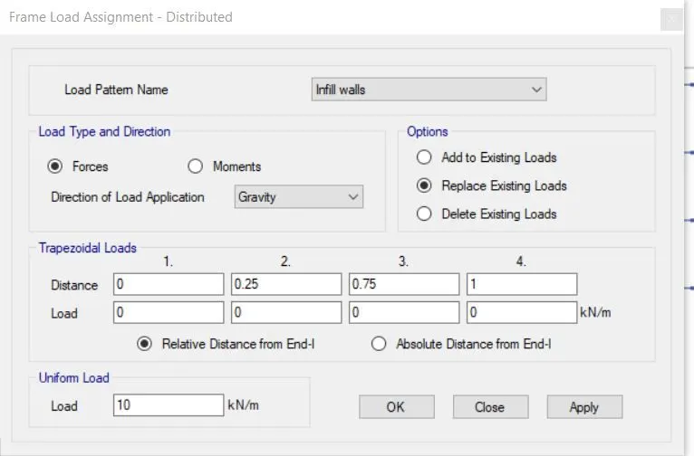
- click on frame loads distributed and then add the masonary infll values as 10 kN/m^2. click ok.
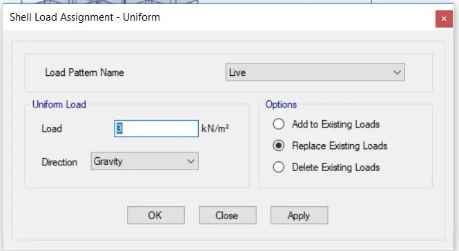
- similaryly select all the slab sections and assign shell loads as 3kN/m^2 note here is for the roof the ll needs to be reduced to 50% that is 1.5kN/m^2.
6.assigning the restrain
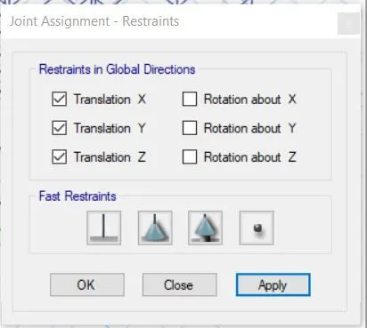
- select the joint and go to assign and then click on restrain and select pinned support click on apply and then ok.
7.Defining the mass source
- go to define tab and select mass source.
- modify the mass source and tick mark the requireed loads.
- add load patters and assign to the model
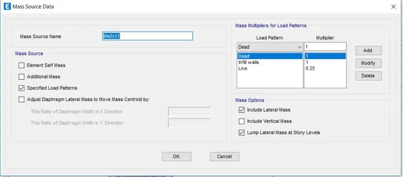
.7. Define load cases
- define the load cses .
- click on the load combinations
- click on the add defiault design combo ok
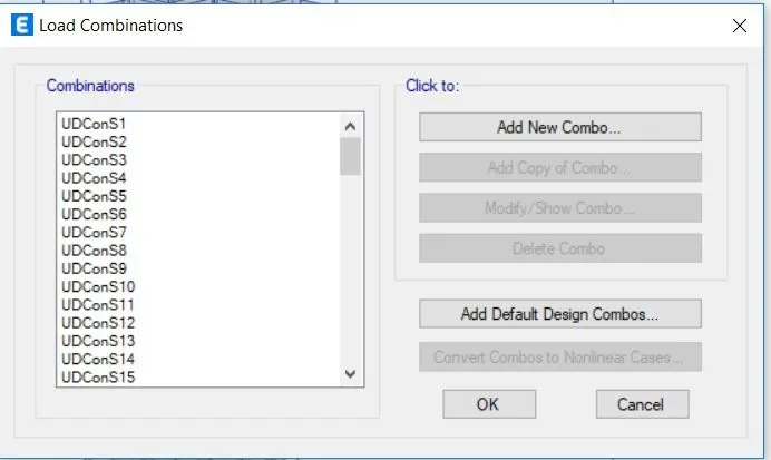
8. Designing the diaphrgam
- seclect all the floors then go to assign then shell then select diaphragam
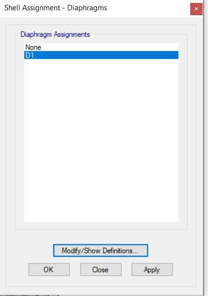
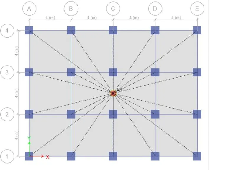
8.Analyse te model using analyise option then click in the check model.
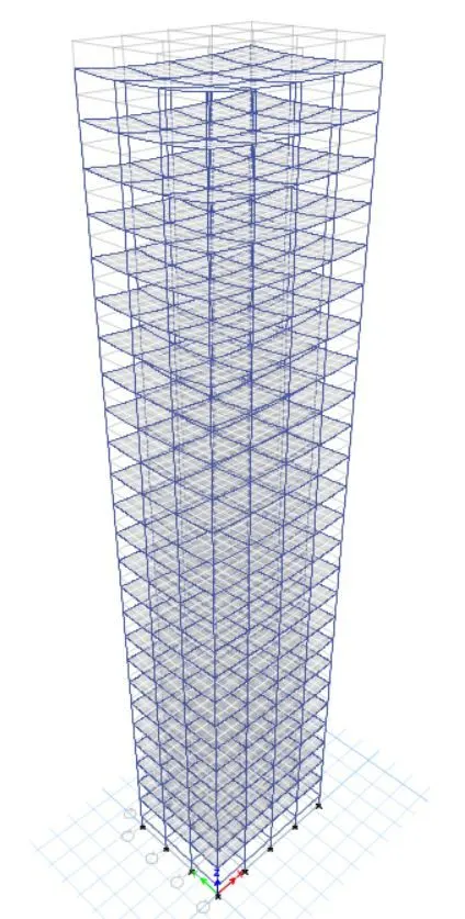
using analyse > run analysis the model is analysed and deflection patters sfd and sfd and bmd are checked
9. results
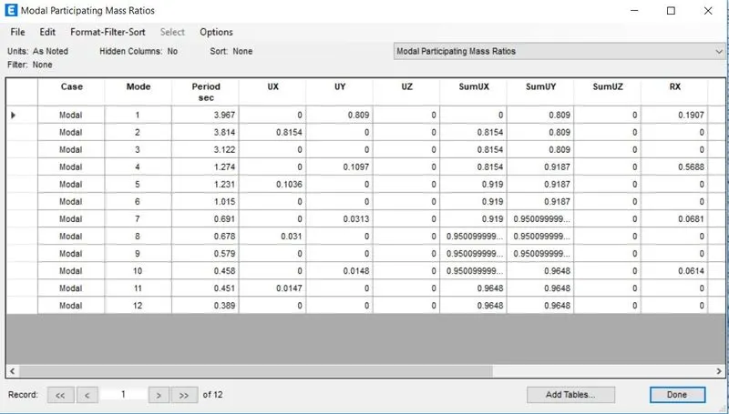
go to display and then click in show tables and select structural output.
.Analysing the results
- Tx1=3.96,Ty1=3.814,Txy1=3.122 seconds.
- so from the results it is clear that the torsional time period is less than two translational time period as required by IS1893 provision table 5.
- when we asdd the 3 modes mass ratios we get 0.919 which means the first three modes odf seismic oscillations contribute more than 655 of the building weight as per Etabs analysis.
- the fundamental natural periods in the two principal directios are away from each other by 10 % from larger value.
- the story drift for servicibility base shear (EQX or EQY) is tabulated from the following path
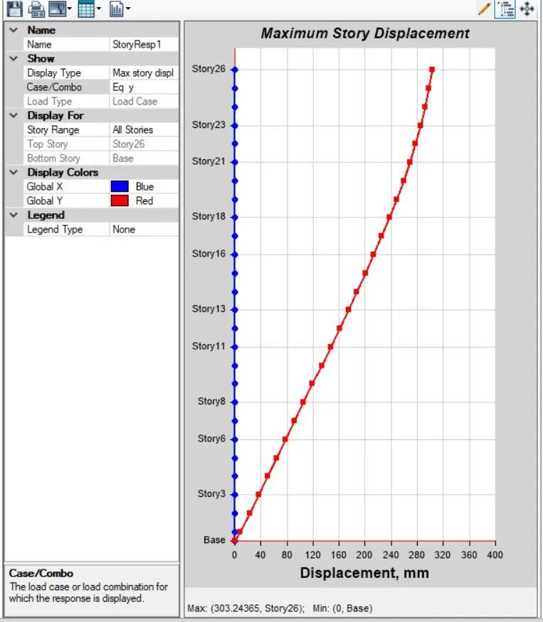
- go to gisplay > storey response plot
- keeping load case to EQY and switching to max drift the maximm drift value noted is 0.0030
- so asper the clause 7.11.11.1 the maximum inter storey drift is limited to 0.004 for each storey height but our value is 0.003 which is within the limits.
- conclusion :- The modelling is done is completed ans analysed in etabs . the results are within the given range