Modelling of 25 storey building with the specified properties using ETABS
AIM: To model a 25 Storey building on ETABS with structural properties as specified below. Ground floor or plinth floor level can be taken at a height of 1.5metres from the base. Each of the successive 25 Storeys has a Storey height of 3metres.
Structural Element Sizes
- Beams: 300 × 400 mm
- Columns: 800 × 800 mm
- Slab: 150 mm thick
Material Properties
- Grade of Concrete: M30
- Grade of Steel Reinforcement Bars: Fe 415 Loading
- Dead Load on beams from infill wall: 10kN/m (Let us assume the same for roof floor in view of parapet)
- Live load on floor: 3kN/m^2 (Let us assume the same for roof floor)
- a) Buildings are assumed to be pinned at the base
- b) All columns in all Storey are of the same size
- c) All beams in all Storeys are of the same size
- d) Building is located on Soil type-II and in Zone-III. Assume other factors if required.
To carry out the following exercises:
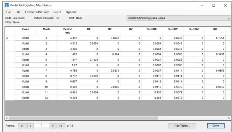
- Check if the translational fundamental natural period of vibration in both the x and y direction is approximately: Tx1Tx1= 4.4 second Ty1Ty1= 4.2 second
- Check if the following provision in Table 5 of IS 1893 (part 1) – 2016, on torsional irregularity satisfied
- Check if the two provisions of clause 7 in Table 6 (shown below) of IS 1893 (part 1) – 2016, regarding vertical irregularity is satisfied
Introduction: -
- ETABS is an engineering software product that caters to multi-story building analysis and design.
- Modeling tools and templates, code-based load prescriptions, analysis methods and solution techniques, all coordinate with
the grid-like geometry unique to this class of structure. - Basic or advanced systems under static or dynamic conditions may be evaluated using ETABS
ETABS modeling is the generalization that multi-story buildings typically consist of identical or similar floor plans that repeat in
the vertical direction. - Modeling features that streamline analytical-model generation, and simulate advanced seismic systems.
- Once modeling is complete, ETABS automatically generates and assigns code-based loading conditions for gravity, seismic,
wind, and thermal forces. - Users may specify an unlimited number of load cases and combinations.
Procedure:
STEP 1:
- Opening ETABS software.
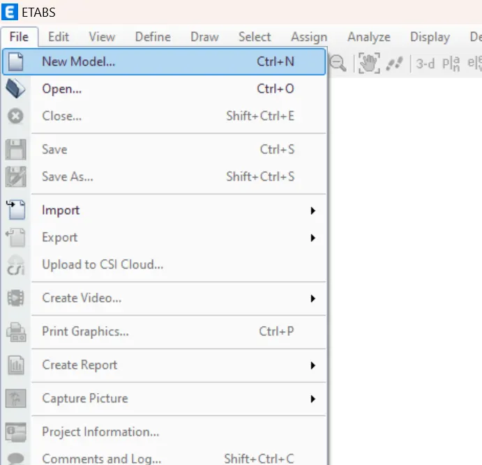
- Click on new model option.
- A dialogue box will appear as model initialization.
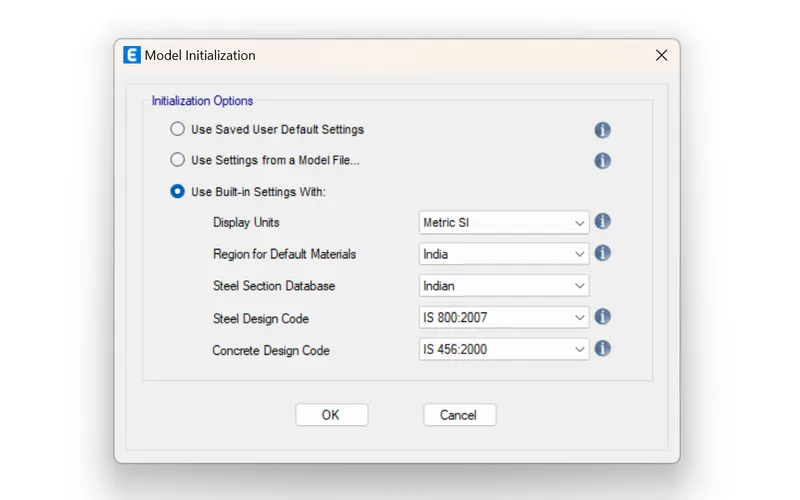
- Choose the built-in settings option and select the display units and codes
- Metric SI<India<India
- After model initialization select the grid and story.
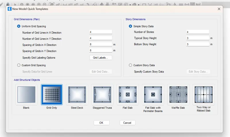
- In this dialogue box choose custom grid spacing and custom story data.
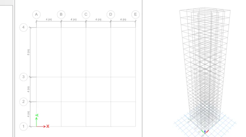
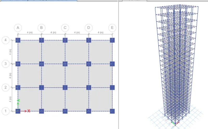
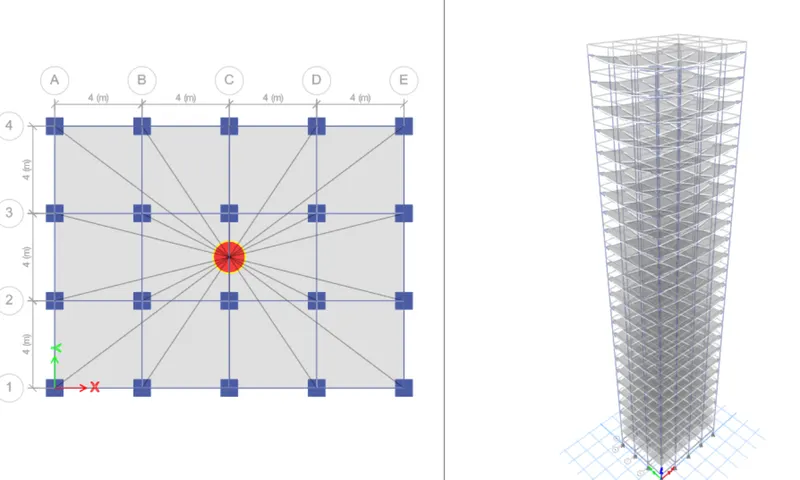
- Enter X grid data at a distance of 4 (Total 16 m) meter and Y grid data at a distance of 4 m (Total 12 m)
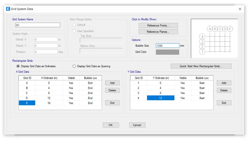
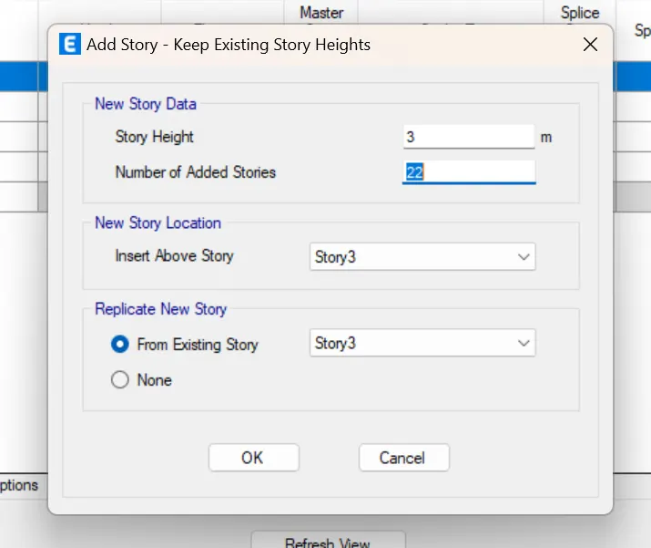
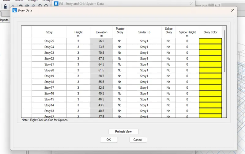
- Edit the stories by using the user defined Storey input,26 Storeys are incorporated (plinth at 1.5-meter height+ 25 Storey with 3-meter height each). Storey 1 has been labelled as master Storey and all above levels are labelled similar.
STEP 2:
Define Materials
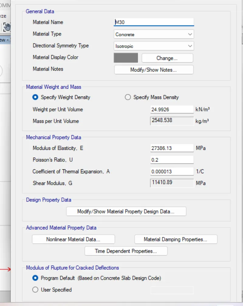
- Select material properties under the define tab.
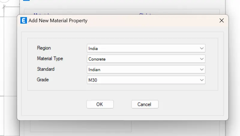
- Define the materials of concrete M30 grade.
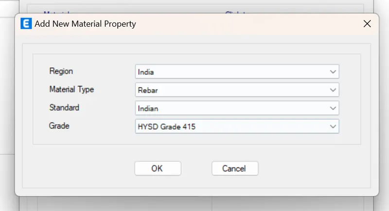
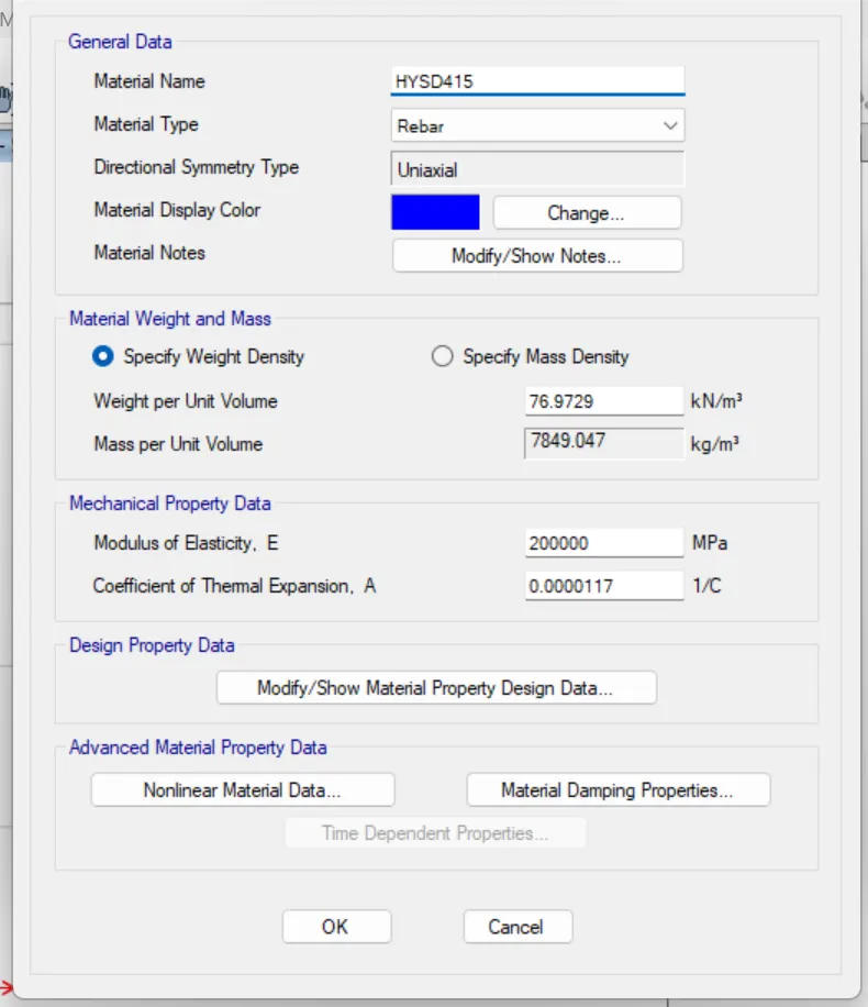
- Define Rebar as Fe415.
STEP 3:
Define Section Properties
- Go to define tab and select selection properties.
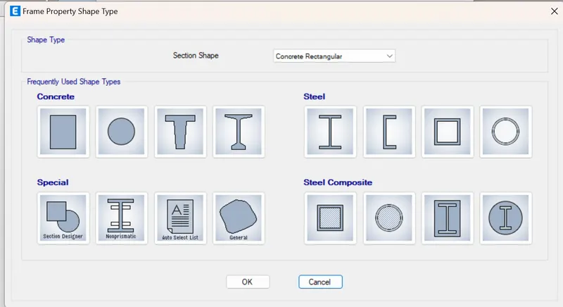
- Click on the frame section and create a new property as concrete rectangular.
- After that give input Property name as B 400x300 and give material as M30 and dimension as 400 in depth and 300width.
- Same as for Column (C 800 x 800)
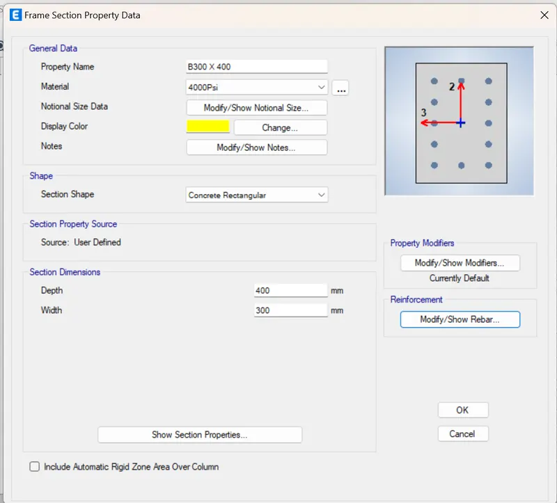
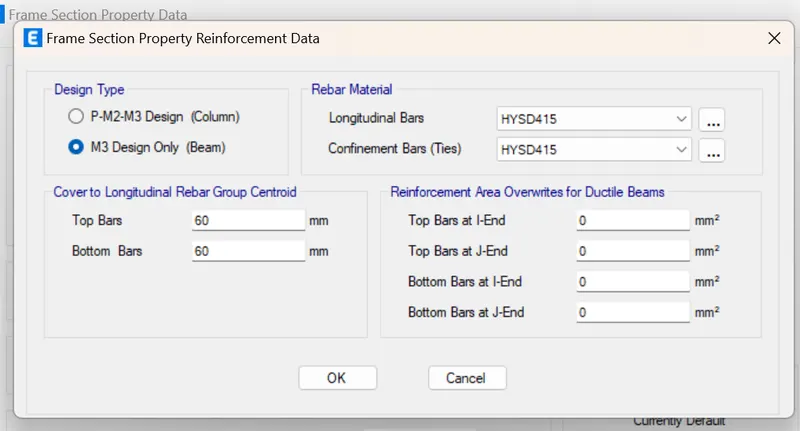
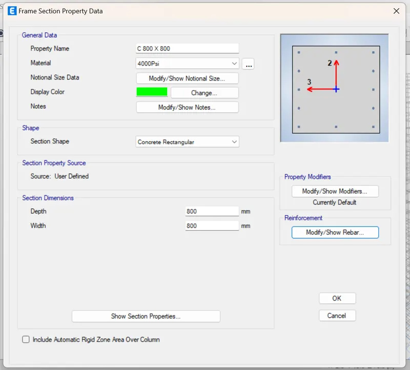
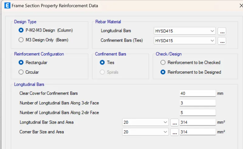
STEP 3:
- Define Slab from Section properties.
- Property name Slab150 < Slab material M30 < Thickness 150mm.
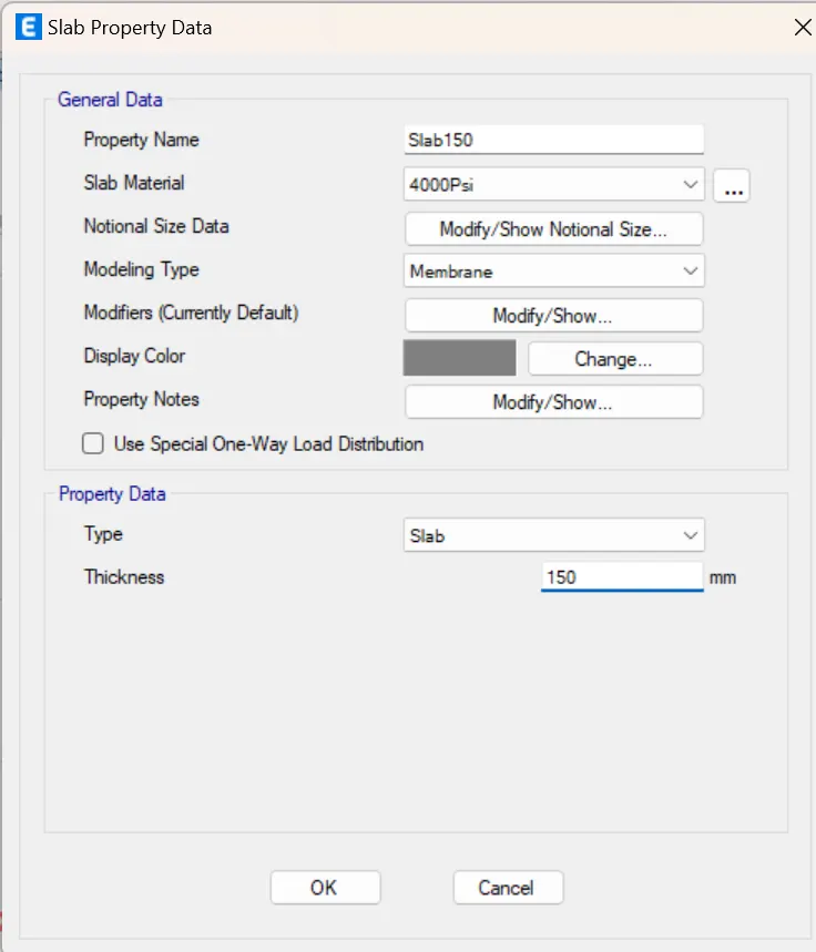
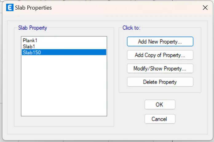
STEP 4
Define Load:
- Go to Define Tab and select load pattern.
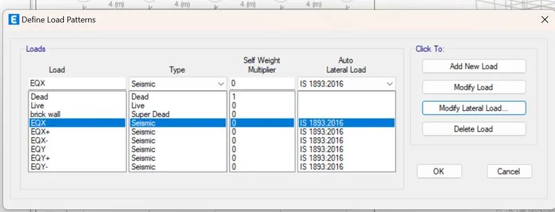
- Modifying lateral load
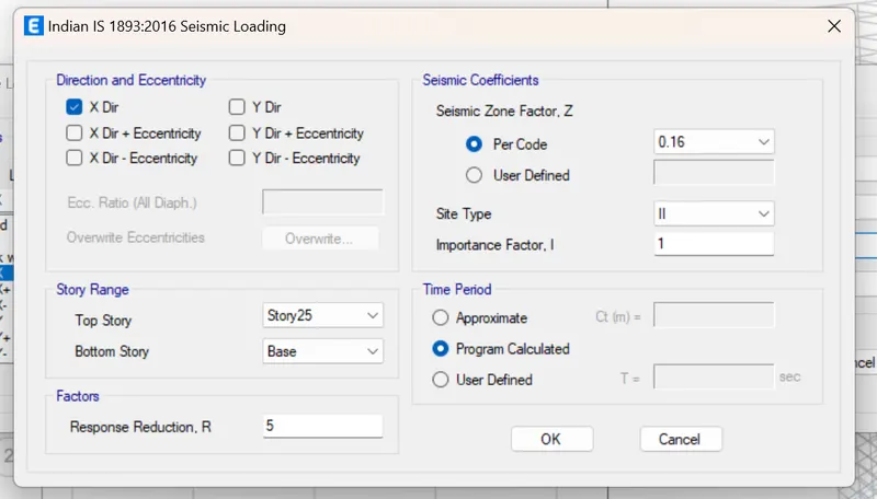
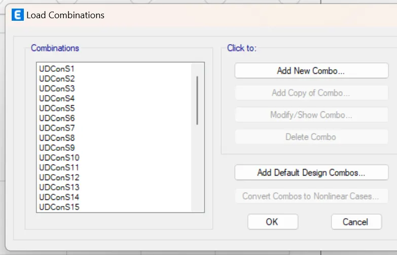
- Now go to again Define Tab and Select Load Combination < Add Default design Combo < Concrete Frame Design
STEP 5:
Draw Properties
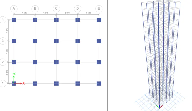
- Select Stories All
- Select Quick Draw Column Tool
- Now draw a column of size 800X800mm at the intersection of the horizontal and vertical grid and beams.
STEP 6:
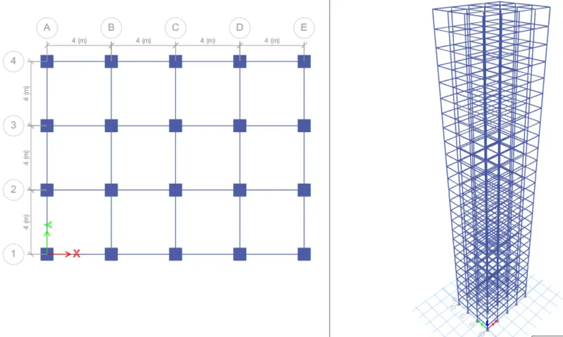
- Beams drawn using quick draw beam tool at all the stories.
STEP 7:
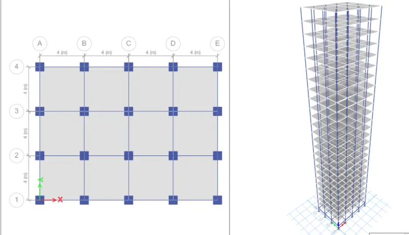
- Select Story 1 and click to similar story.
- Using the quick draw floors option Draw the Floor.
STEP 8:
- Assigning joints
- Select Base of the building and select One story
- Select all the column
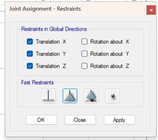
- Go to assign Tab < Joints < Restraint < Pinned joint
STEP 9:
Applying Load
- Assign the loads and select similar stories.
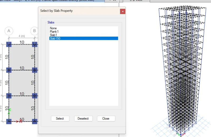
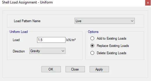
- Loads on Floors
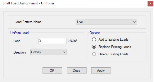
- Click on shell load under the assign tab
- Click on live load and give value as 3kn/m^2.
- Click on apply.
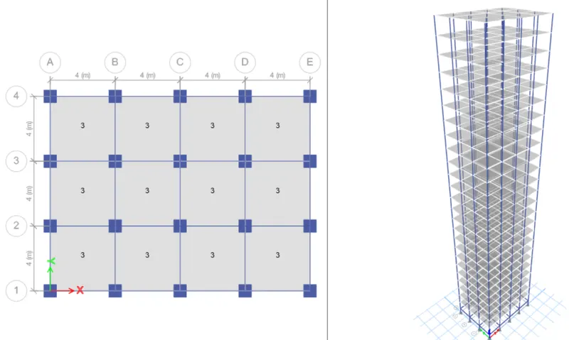
- For roof we will take only 50% of the live load.
STEP 10:
Loads on Frames
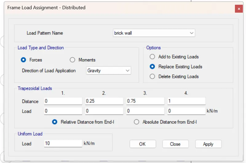
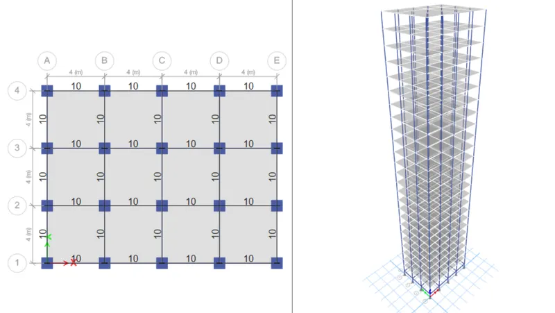
- Similarly add live load of 10Kn/m^2 on all the beams at similar story.
- For that select all the beams from select object type beams.
- Go to the frame load and click on the distributed load and enter the value as 10Kn/m^2.
STEP 11:
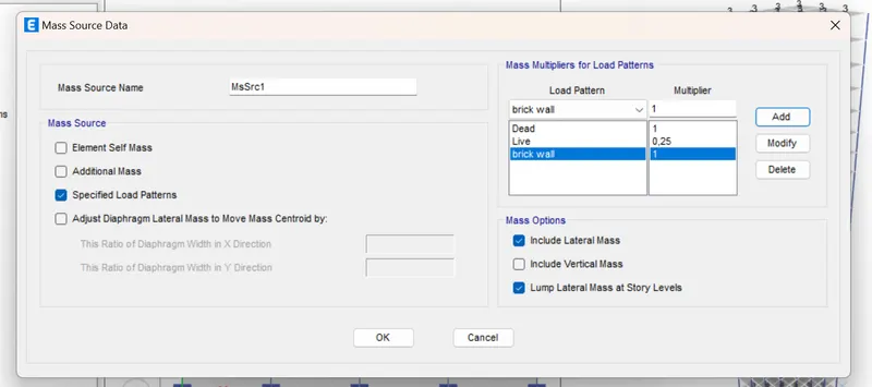
- Now go to mass source from the define tab.
- Modify the mass source.
- Add load patterns and assign to the model.
- Dead =1 < Live load=0.25 < Wall=1
STEP 12:
Diaphragm for the Building
- Now create the diaphragm by going to the assign tab then shell and select diaphragms.
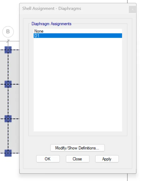
- Click on ok.

STEP 13:
Analyzing the Model
- Before Analyzing model, we have to check any errors from Analyze tool.
- No errors
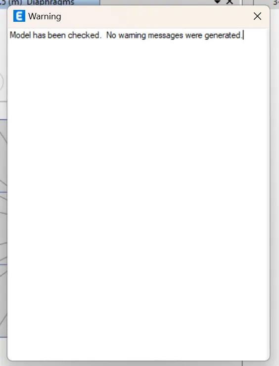
Now Analyze the Model.
Analyzing Successful.
Checking the Tables and Deforms Shapes of the Model.
STEP 14:
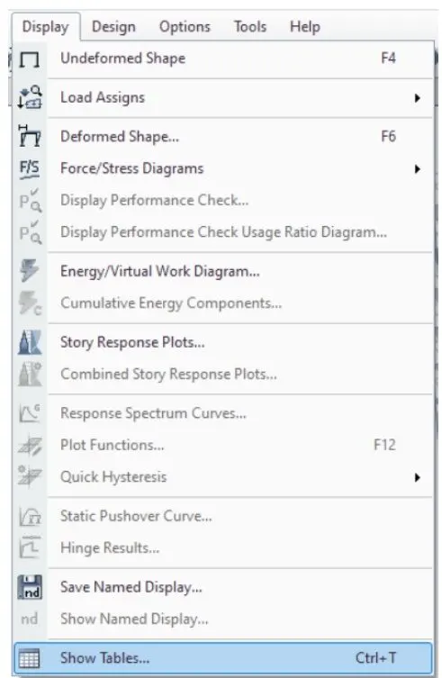
- Next, from the display option we select the show tables option, as shown below.
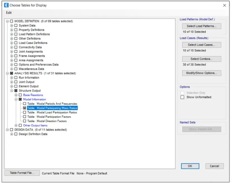
- After selecting the show tables option the new tab will be visible.
- Now we select the Modal Participating Mass Ratios and click on the ok button, as shown below.
- Next the Modal Participating Mass Ratios table will be visible, as shown below.
RESULT: -
The 25 Storey building has been modelled successfully in the ETABS