Modelling of 25 storey building with the specified properties using ETABS
Challenge 6 – ETABS modelling of a 25 storey building
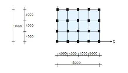
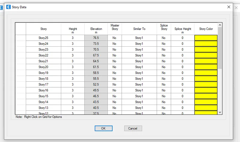
Model a 25 storey building on ETABS with structural properties as specified below. Ground floor or plinth floor level can be taken at a height of 1.5 metres from the base. Each of the successive 25 storeys has a storey height of 3 metres.
Structural Element Sizes
- Beams : 300 × 400 mm
- Columns : 800 × 800 mm
- Slab : 150 mm thick
Material Properties
- Grade of Concrete : M30
- Grade of Steel Reinforcement Bars : Fe 415
Loading
- Dead Load on beams from infill wall : 10 kN/m (Let us assume the same for roof floor in view of parapet)
- Live load on floor : 3 kN/m2 (Let us assume the same for roof floor)
a) Buildings are assumed to be pinned at the base
b) All columns in all storey are of the same size
c) All beams in all storeys are of the same size
d) Building is located on Soil type-II and in Zone-III. Assume other factors if required.
ANSWER
AIM:
Model a 25 storey building on ETABS with structural properties as specified below. Ground floor or plinth floor level can be taken at a height of 1.5 metres from the base. Each of the successive 25 storeys has a storey height of 3 metres.
PROCEDURE:
STEP1
- Open E-Tabs ->new file
- A new tab will open
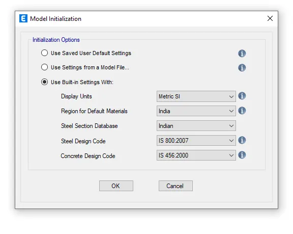
- Choose the built-in settings option and select the display units and codes.
- After model intialization is done select the grid and story inputs from the New model quick templates dialogue box.
- In this dialogue choose custom grid spacing and custom story data which is used to provide the inputs specified above.
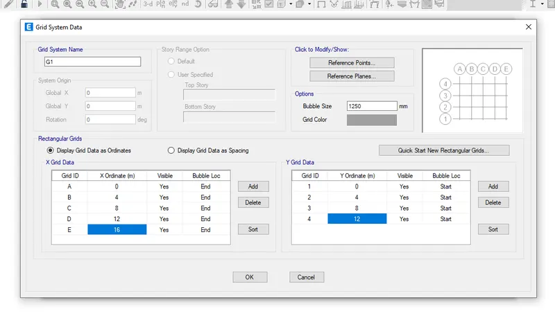
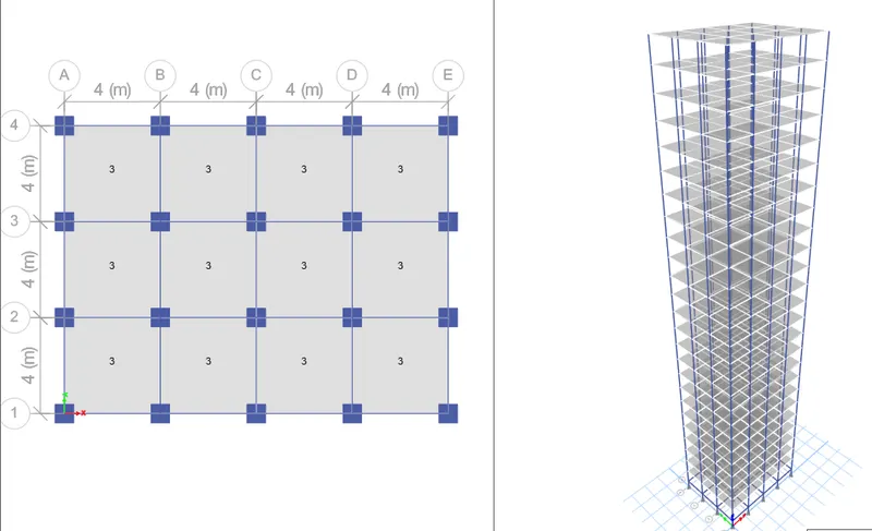
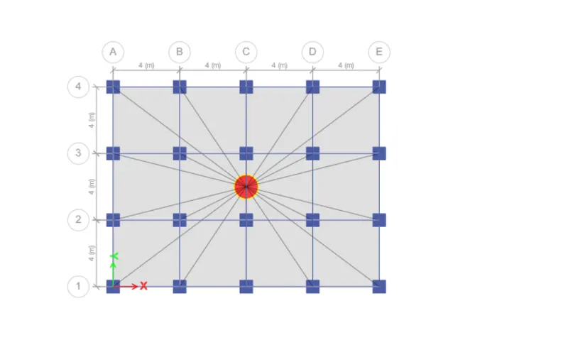
- Enetr X grid data at a distance of 4 metreand Y grid data as 4 at a distance of 4 metre.
- Select material properties under the define tab.
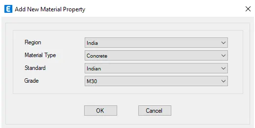
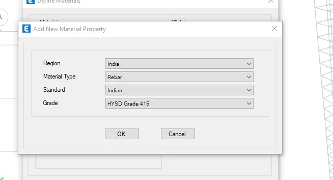
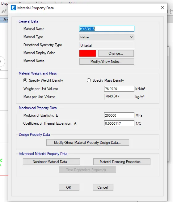
- Define the materials of concrete M30 grade and steel of transverse reinforcement as 415 grade and longitudnal reinforcement as 500 grade.
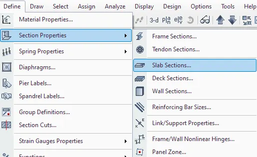
- Select Section properties under the define tab.
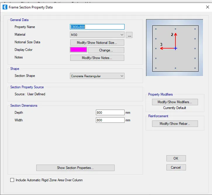
- Click on the frame section and create a new property as beam and input the values as 300X400mm.
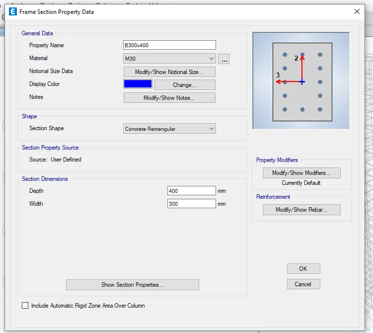
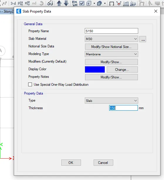
- After the define properties for the column as 800X800 and slab thickness ass 150mm
- Now define the load patterns: click on the define ta and click on load patterns.
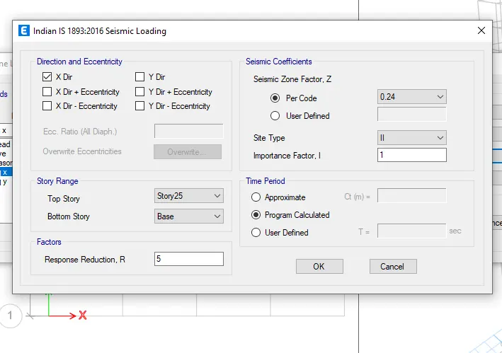
- Define the loads like dead load,live load,brick load,earth quake load in x direction and positive x and negative x and same loads in the Y direction also.Mention IS codes of respective loads.
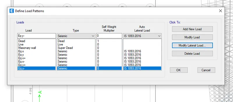
- Click on modify lateral load,set range from base to 25th storey and seismic zone factor as 0.36,importance factor 1.25 and time period 0.5 seconds.
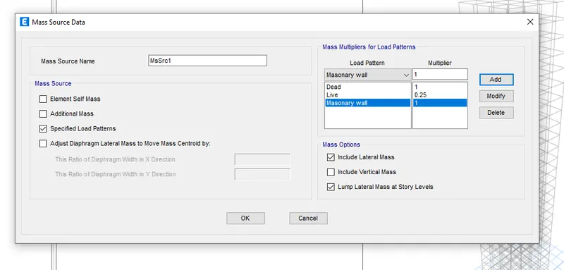
- Now go to mass source from the define tab.
- Modify the mass source and tick mark the required loads.
- Add load patterns and assign to the model.
- Now load combination will be defined
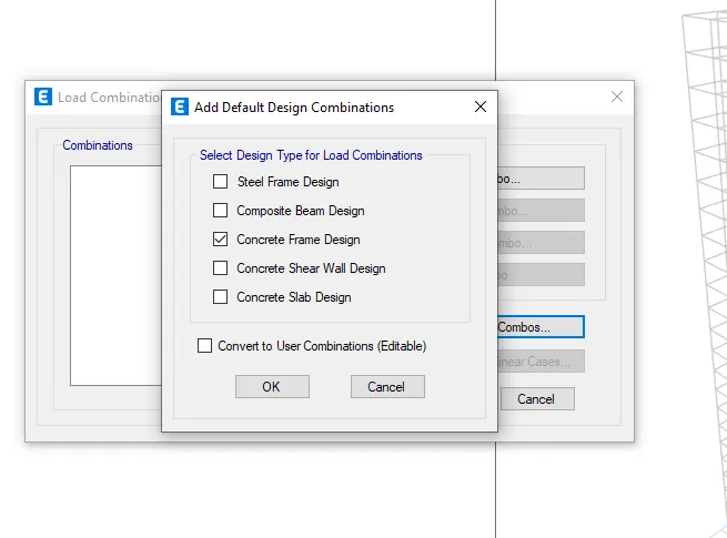
- From the define menu->go to load combination
- a new tab will open->click on Add default design combos
- Select concrete frame design
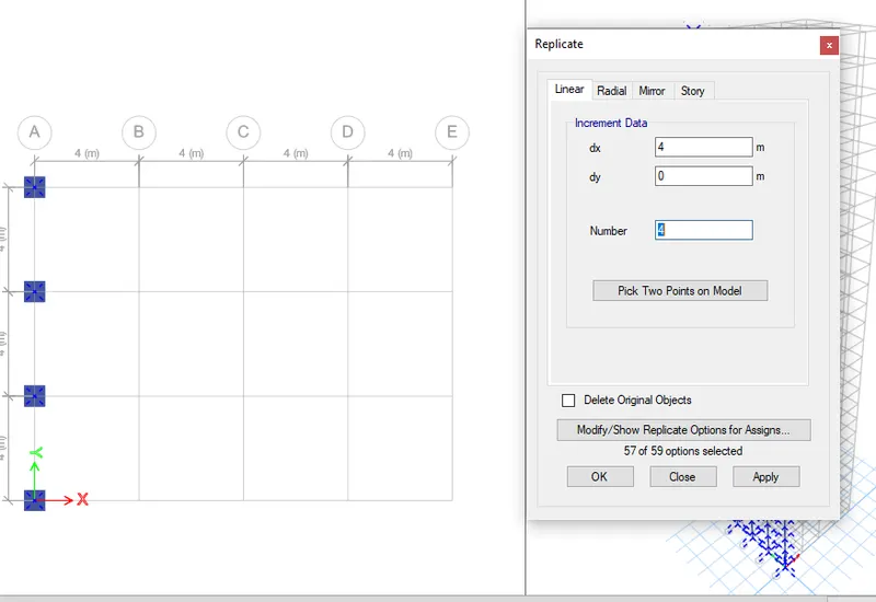
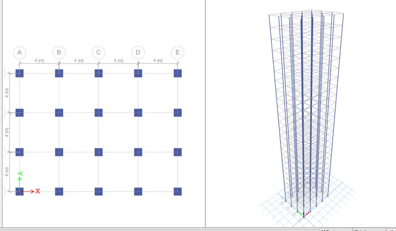
- Now we will add columns to the structure.
- Go to bottom right corner and select ALL STORIES
- Click on "Quick draw columns" of left side toolbars->a new tab will open
- select the C800x800 from the property
- select all the columns ->all the columns will be applied to the grids
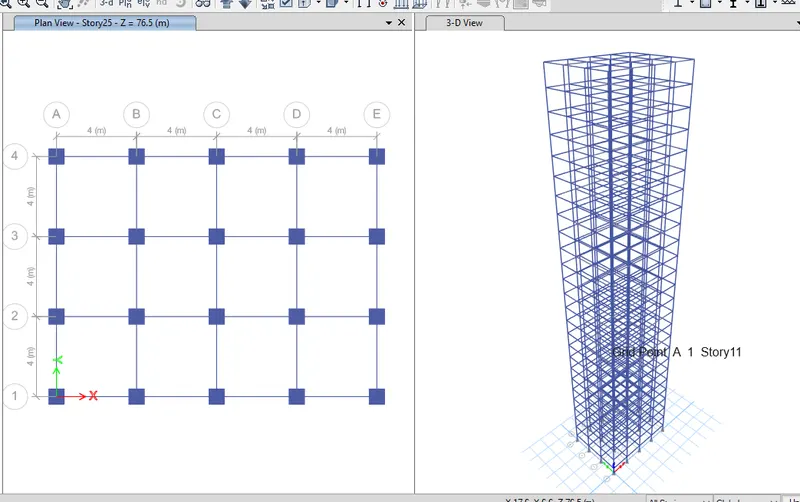
- Now beam will be added->Select quick draw beams (keep the selection to ALL stories)
- a tab will open->select the property to B300x400
- select all the beams section->the beams will be applied
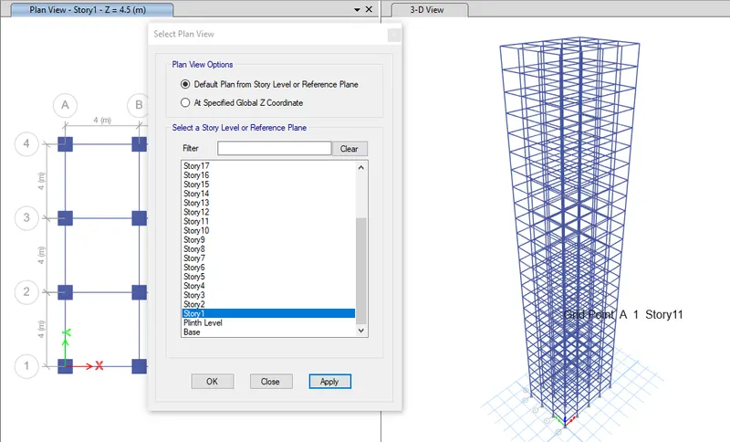
- Now add slabs to the section-Select quick draw floors/Slabs
- a tab will open->change the property to slab 150
- Change the selection To similar stories
- select all the slabs of any one floor ->the floors will be applied
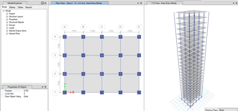
- Similarly add live load of 10Kn/m^2 on all the beams.
- For that select all the beams from select object type beams.
- Goto the frame load and click on the distributed load and enter the value as 10 Kn/m^2.
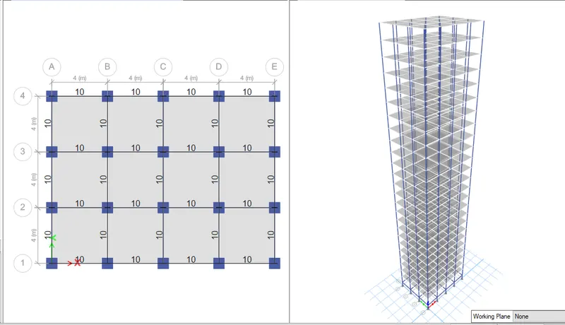
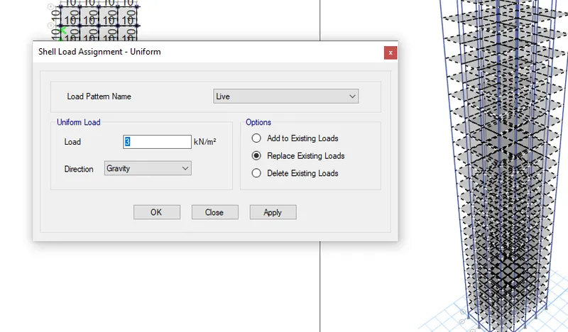
- Do the same for all the earthquake loads.
- Assign the loads and select similar stories.
- Click on shell load under the assign tab.
- Click on live load and give value as 3kn/m^2.
- Click on apply.
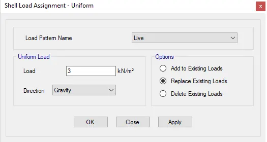
- For the roof we will take only 50% of the live load.
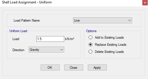
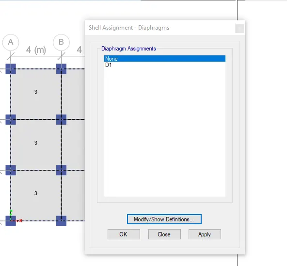
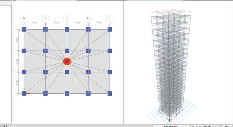
- Now create the diaphragm by going to the assign tab then shell and select diaphragms.
- Click on ok.
Results:
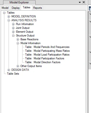
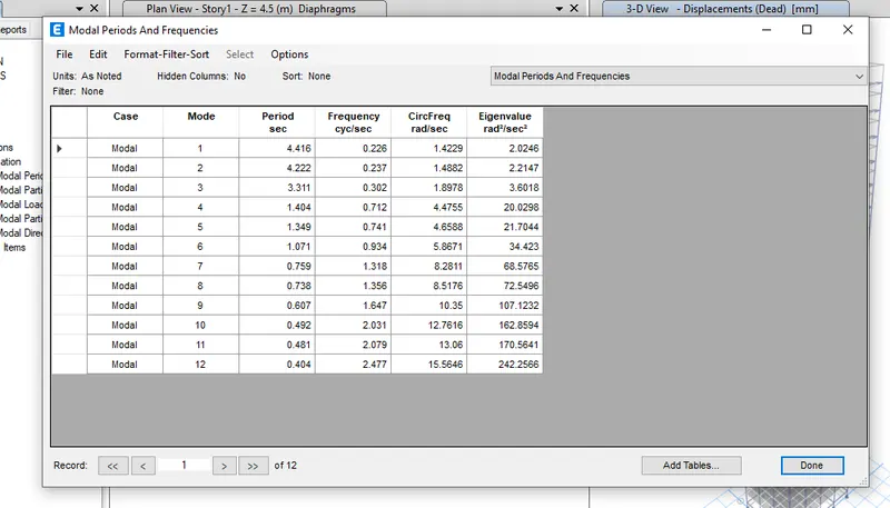
- Now click on Display>show tables>Analysis results>Structure ouput>Modal information>modal periods and frequencies.
- The time periods for fundamental mode-1Y direction and findamental Mode -1X direction are noted from the table and are as follows:
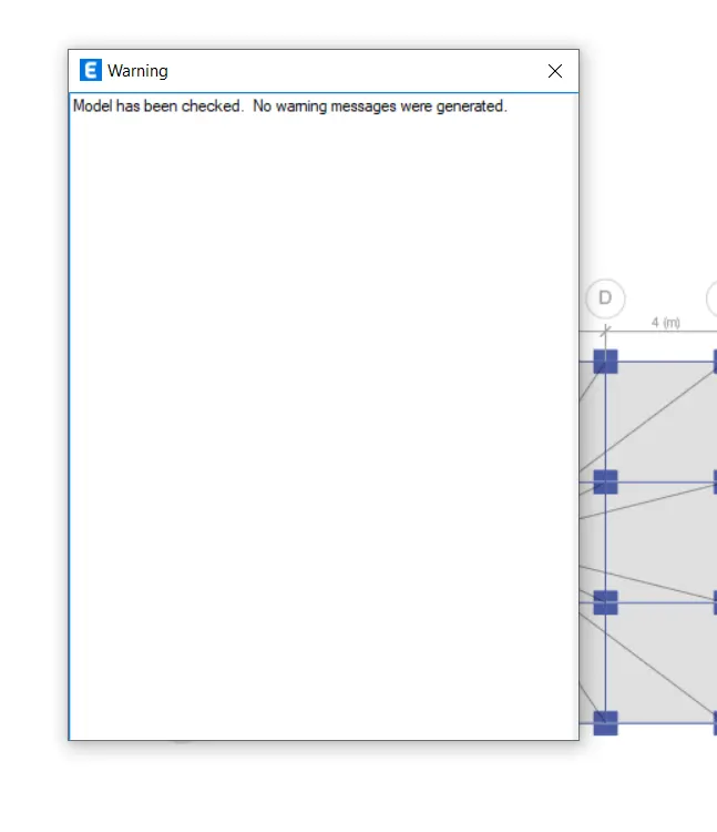
- Using analyze>run analysis,the model is analysed and deflection patterns,BMD/SFD patterns are cross checked logically.It is understood that the worked model provides reliable results.
Carry out the following exercises:
- Check if the translational fundamental natural period of vibration in both the x and y direction is approximate: Tx1��1= 4.4 second Ty1��1= 4.2 second

4.416 For first period
4.222 for second perioD
This check will help confirm if modelling is done correctly. Some deviations from the above values is possible (± 2%). But any major deviation will suggest an error in modelling.
- Check if the following provision in Table 5 of IS 1893 (part 1) – 2016, on torsional irregularity satisfied:
YES
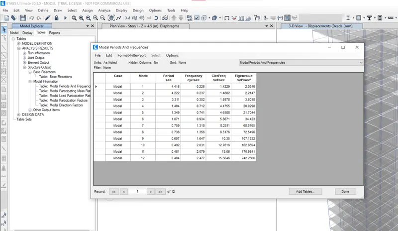
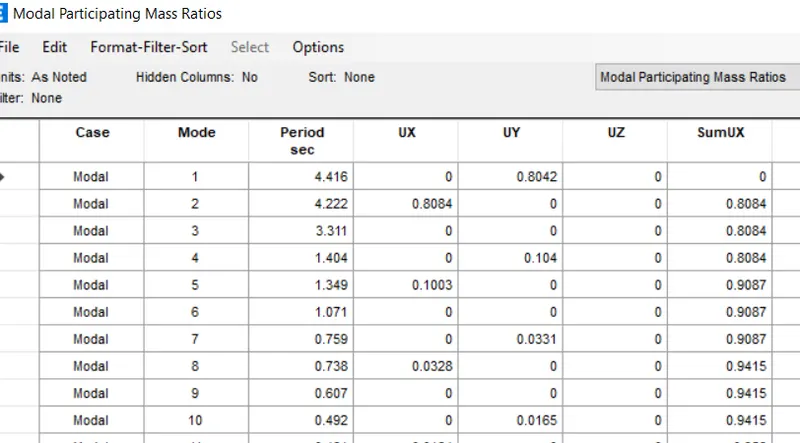
- As in the figure we can see that in the first time period the mass participating is about 80%
- the natural period corresponding to the torsional mode of oscillation must be less than the two fundamental translational modes of oscillation along each principal plan directions.
- No
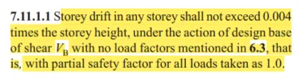
- Check if provision on inter-storey drift limitations in clause 7.11.1.1 satisfied. Please note that this check is for Serviceability Limit State and hence is for situation when stucture is subjected to unfactored seismic base shear
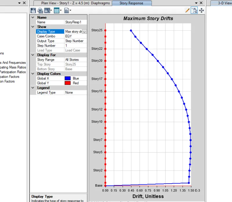
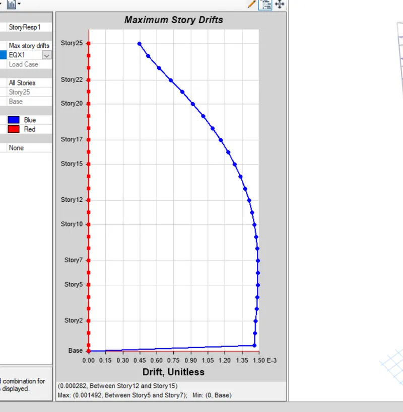
yes we achived it