Modelling of 25 storey building with the specified properties using ETABS
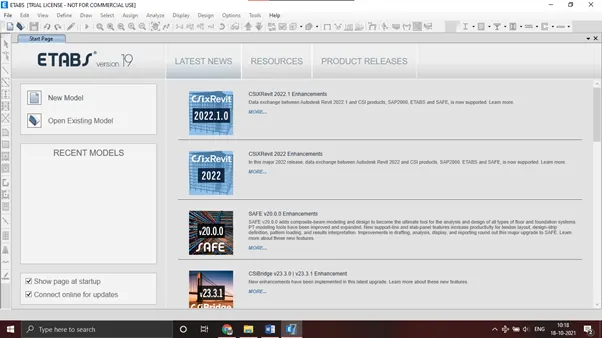
Initially open the ETABS application and click on the new model option from the file menu.
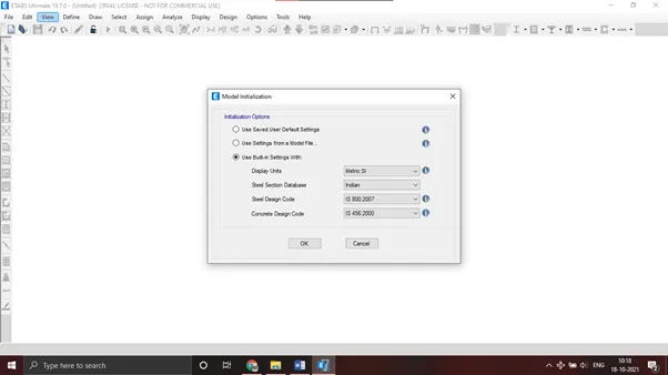
Now in the model initiation window desired units, Design codes which are to be used was selected and then click OK.
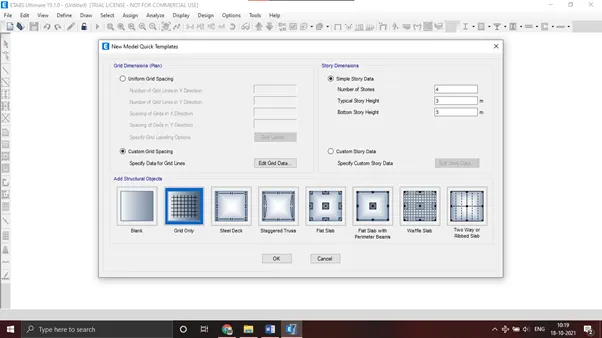
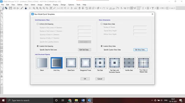
In New Model Quick templates under grid dimensions select the custom grid spacing and then click edit grid data.
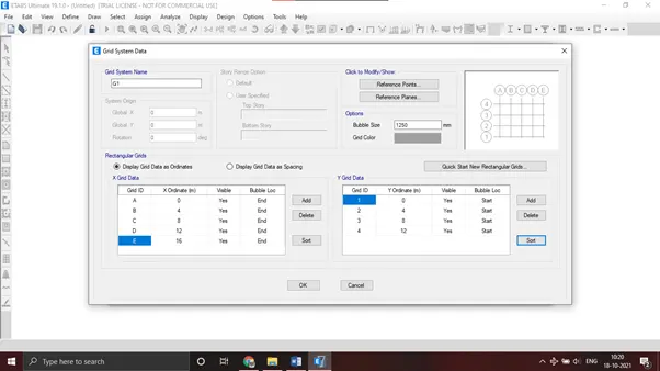
The grid dimensions was inserted according to question as follows and click OK.
In New Model Quick templates under Story dimensions select the custom story data and then click edit story data.
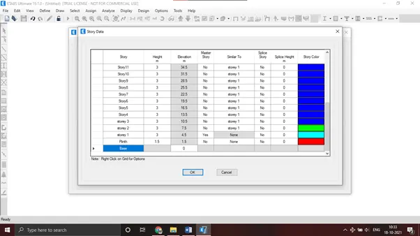
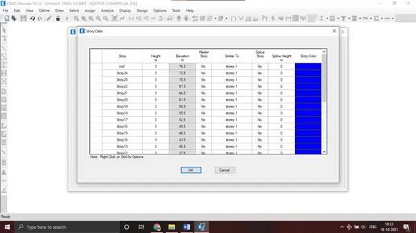
Now input the storey details as given in question and story 1 was selected as the master story and was applied to rest story from 2nd story to roof and then click OK.
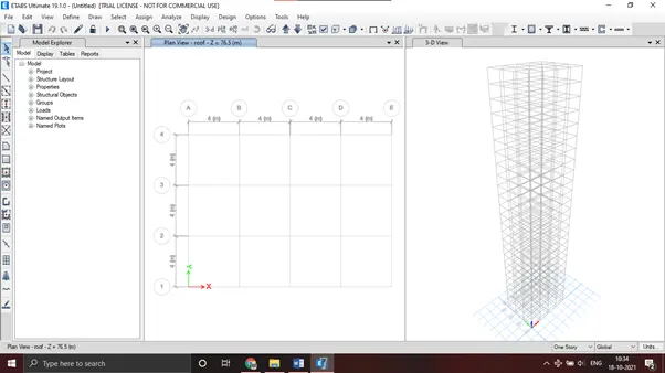
The plan and 3D view of all the data’s which we have given till now is shown on the image below.
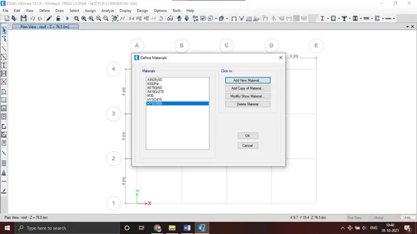
Now to define the properties of elements, go to define menu and then select material properties. The grade of concrete was selected and click ok.
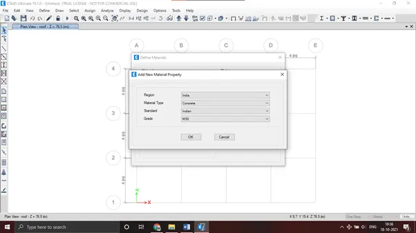
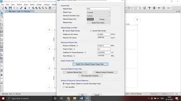
The material property data dialogue box will show up, ensure all the data’s are correct and then click Ok at the bottom.
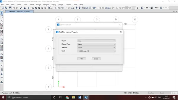
Similarly HYSD 500and HYSD 415 steel was added.
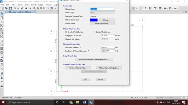
Steel and Concrete properties was added to the list now as shown and then click OK.
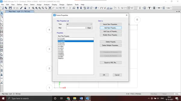
To add frame members like beams, columns and slab go to Define Properties- Section Properties- frame sections options. From the frame properties dialogue box click on add new property option.
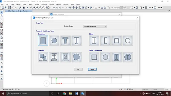
From the frame property shape type select the rectangular concrete option and click OK.
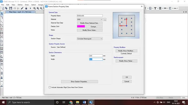
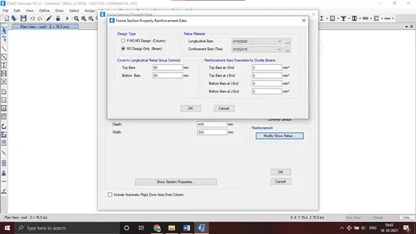
Beam details was provided as shown in figure and then click on Modify/ Show reinforcement under reinforcement section.
Beam reinforcement data’s:
Select M3 Design Only (Beam) and chose the rebar materials as shown and click OK.
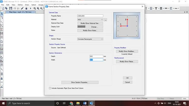
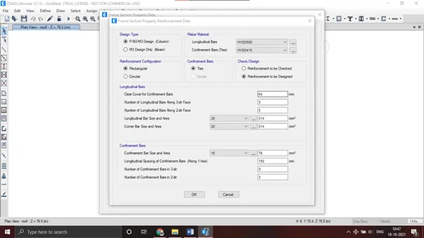
In the similar manner apply the column data’s as shown below
Column reinforcement data:
Slab properties:
For that Select Slab section from the section properties under Define menu.
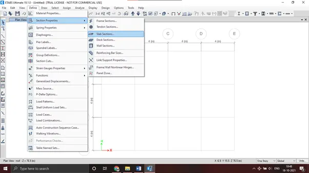
Select add new property option.
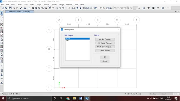
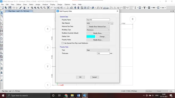
Slab properties like thickness and other details are added as shown below and then click OK.
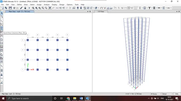
So all the properties of frame members have been added correctly, now we have to place the structural members. For this select quick draw column option from the tools available at the left side of the screen and place the columns at all the grid intersections. Also select all storeys at the right bottom of screen to apply it to all storeys.
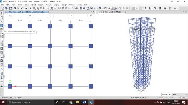
In the similar way using the quick draw beams option beams was also drawn as shown
Using the Quick draw floor option slabs was placed between the grids in all floors as shown.
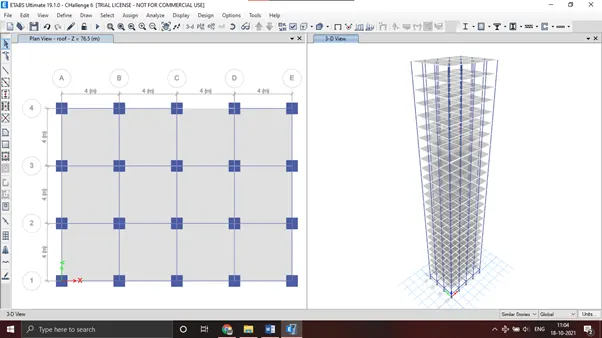
Now to Change the base connections initially go to the base view in the plan and select the base view. Now in assign tab- select joints- restraints. Now from the dialogue box that appears select pinned connections and then click OK.
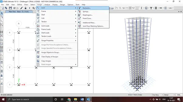
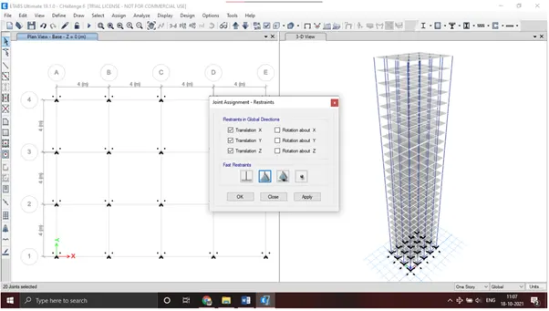
To assign loads to the structure, select define followed by load patterns to open the Define load pattern dialogue box.
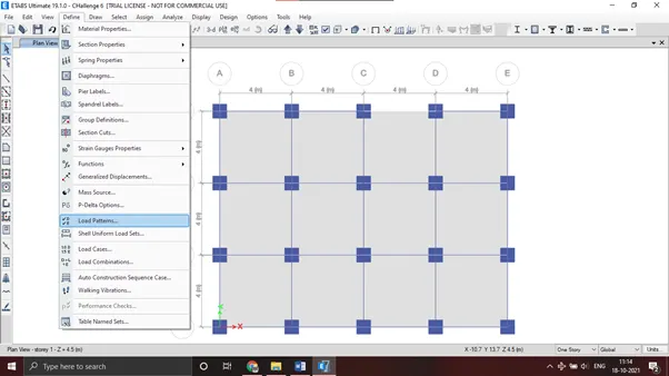
Define load pattern dialogue box.
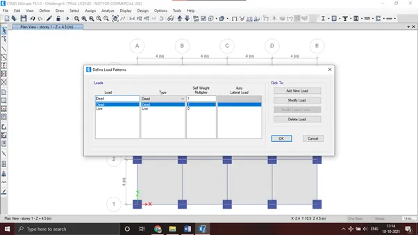
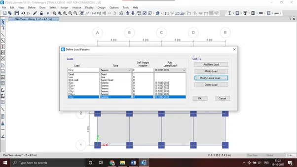
The various loads which are applied are as shown below
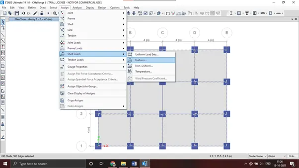
Now to apply the live loads follow these steps. In Assign menu- Select Shell Loads followed by Uniform loads as shown.
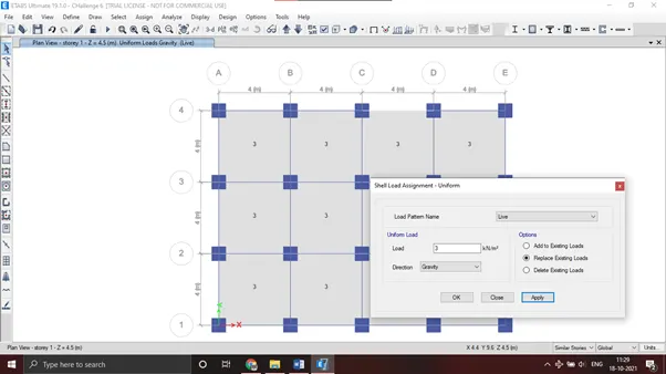
Live load of 3kN/m^2 was applied and in options select replace existing loads.
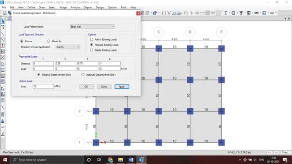
To assign loads on beams as brick wall follow these steps.
Under the Assign menu select Frame loads followed by distributed loads as shown.
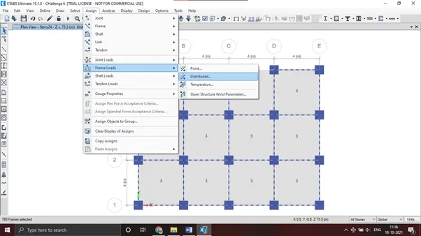
Brick load of 10kN/m was applied as shown
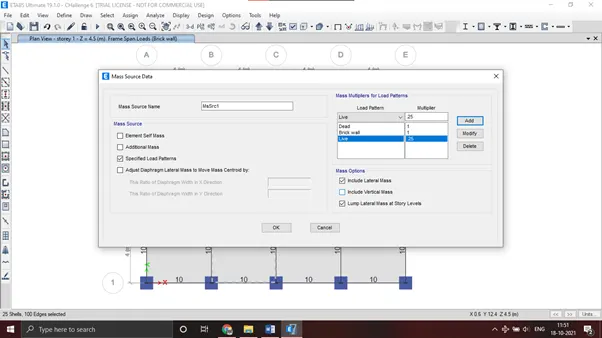
To assign mass source to model follow these steps.
In define menu select mass source options to open the mass source dialogue box.
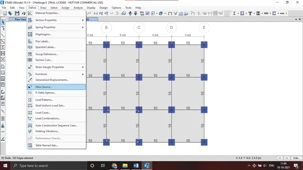
Now select Modify mass source data option and click OK
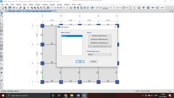
Now mass source data was provided as shown and load pattern was also added to it.
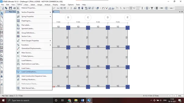
In order to generate load combinations click on Define menu and select load combinations to open the load combinations dialogue box.
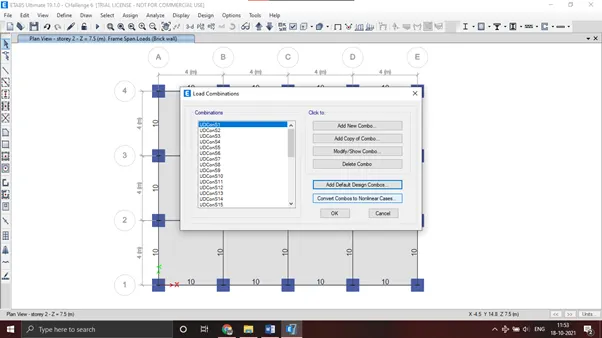
From the load combination dialogue box select add default design combos and then click OK.
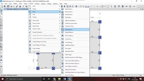
To assign diaphragm to the model follow these steps:
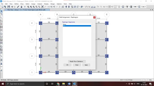
In assign menu select Shell followed by Diaphragm to open the shell Assignment diaphragm dialogue box
Select D1 from the diaphragm assignments and click apply followed by OK.
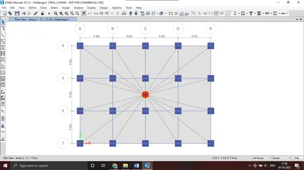
The Diaphragm D1 is applied and is as shown below.
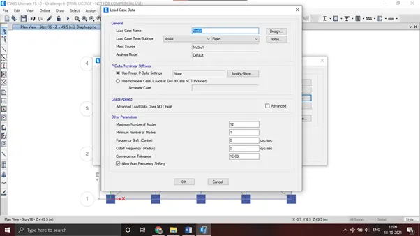
To create the modal analysis go to define tab- modal cases- and select modify and enter the data’s as shown in image
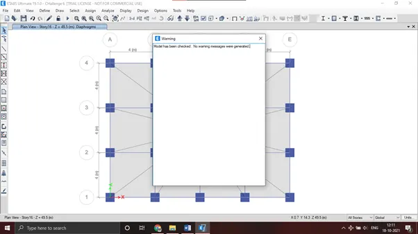
To check the model for errors go to Analysis tab and select check model.
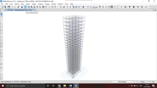
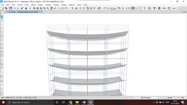
3D view after running the analysis.
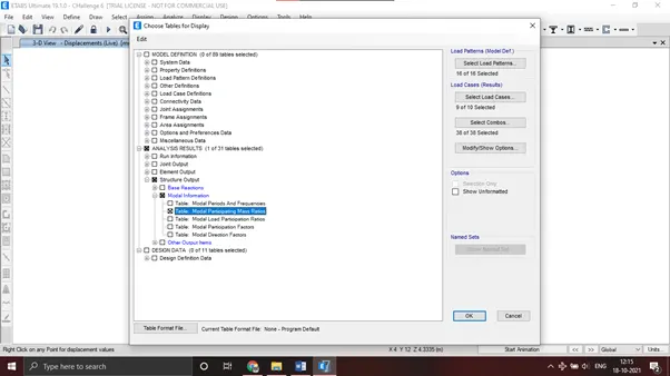
Initially go to display tab -Show tables -Analysis result -Structure output- Modal information- Modal participation and mass ratios and click OK.
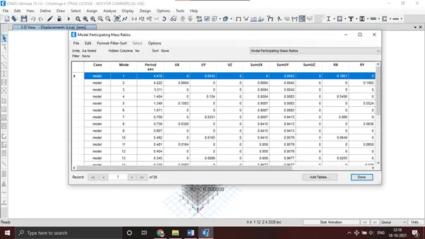
Modal participation and mass ratio table is as follows.
CONCLUSION:
ETABS model was completed and analysed.