Modelling of 25 storey building with the specified properties using ETABS
Challenge 6 – ETABS modelling of a 25 storey building
Model a 25 storey building on ETABS 2018 with structural properties as specified below. Ground floor or plinth floor level can be taken at a height of 1.5 metres from the base. Each of the successive 25 storeys has a storey height of 3 metres.
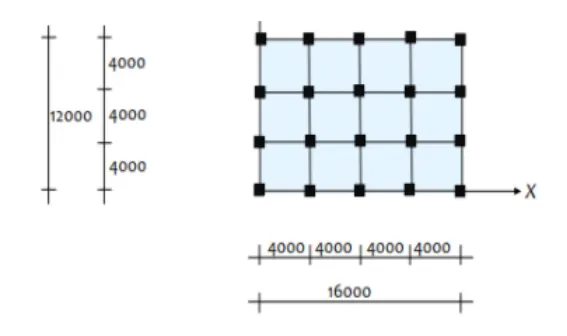
Structural Element Sizes
• Beams : 300 × 400 mm
• Columns : 800 × 800 mm
• Slab : 150 mm thick
Material Properties
• Grade of Concrete : M30
• Grade of Steel Reinforcement Bars : Fe 415
Loading
• Dead Load on beams from infill wall : 10 kN/m
• Live load on floor : 3 kN/m2
Buildings are assumed to be pinned at the base
All columns in all storey are of the same size
All beams in all storeys are of the same size
Carry out the following exercises:
• Check if the translational fundamental natural period of vibration in both the x and y direction is approximately the following:
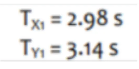
This check will help confirm if modelling is done correctly. Some deviations from the above values is possible (± 2%). But any major deviation will suggest an error in modelling.
• Check if the following provision in Table 5 of IS 1893 (part 1) – 2016, on torsional irregularity satisfied:
The natural period corresponding to the torsional mode of oscillation must be less than the two fundamental translational modes of oscillation along each principal plan directions.
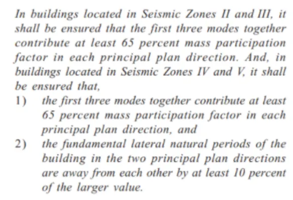
• Check if the two provisions of clause 7 in Table 6 (shown below) of IS 1893 (part 1) – 2016, regarding vertical irregularity is satisfied
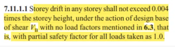
Check if provision on inter-storey drift limitations in clause 7.11.1.1 satisfied. Please note that this check is for Serviceability Limit State and hence is for situation when stucture is subjected to unfactored seismic base shear
Aim:
Modelling a 25 storey building on ETABS 2018 with structural properties as specified in the question.
Procedure:
I. Open etabs software and click on file
II. And the click on the new model
III.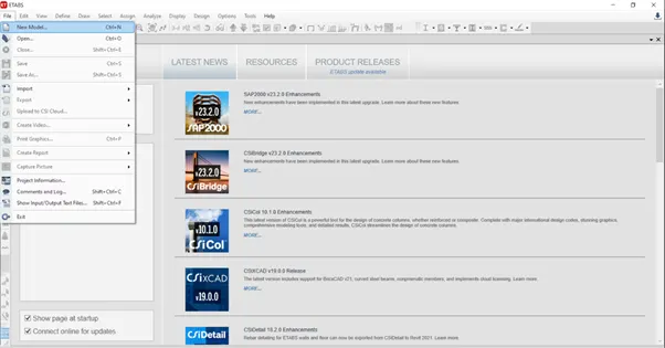
IV. And in the popup set the display units and other parameters as shown in figure below
V.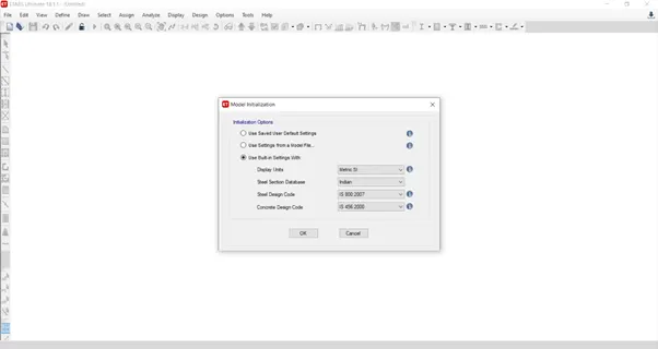
VI. Ok
VII. In the grid settings set as shown in the figure below
VIII.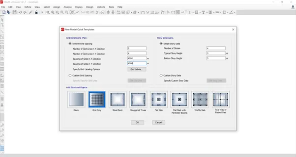
IX. And click on the custom storey data
X. And add the required storey in the pop up
XI.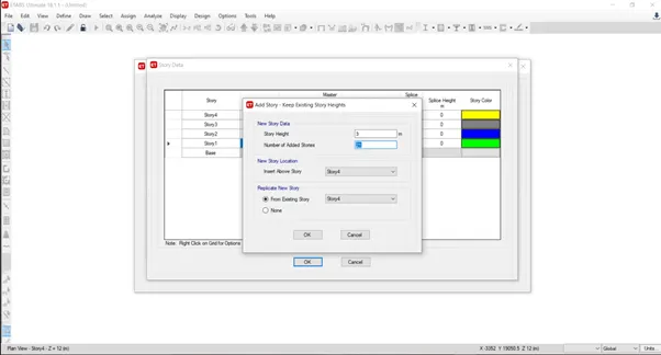 XII. Where 25 stories were added with no to the master story and similar to the story one
XIII. Height of the 3m for every floor
XIV. And 1.5m for the plinth floor.
XV.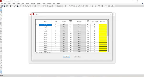
XVI. Ok
XVII.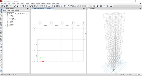
XVIII. Here plan view and the 3d view of the structure will be visible
XIX. Next define materials
XX. In menu bar click on the define and select the material properties
XXI. In the popup select add new material
XXII.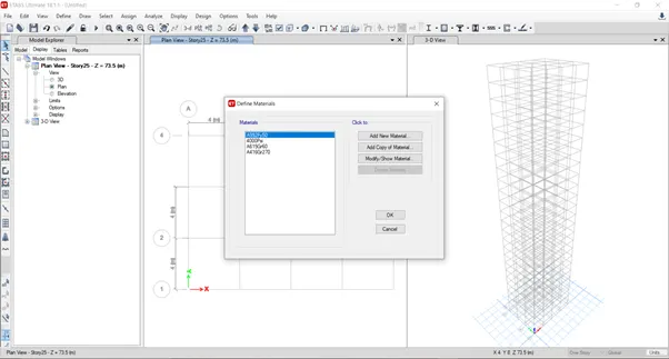
XXIII. Next select the region and material type
XXIV.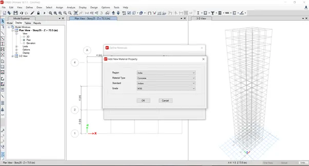
XXV. In next popup add the desired properties
XXVI.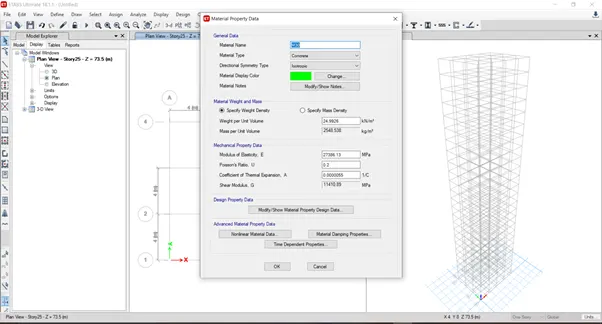
XXVII. Similarly, for the both rebars define the material
XXVIII.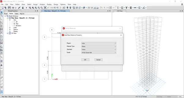
XXIX.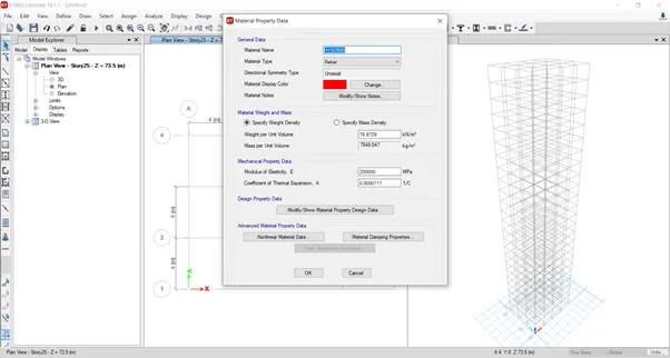
XXX. Now in menu bar select the section properties
XXXI. And select the frame sections
XXXII.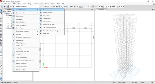
XXXIII. Add new property
XXXIV. Select the desired cross section here rectangular
XXXV. In next add all the required properties
XXXVI.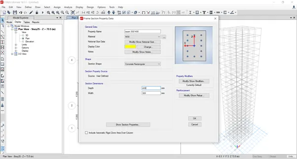
XXXVII. Next select its longitudinal and the confinement bars
XXXVIII.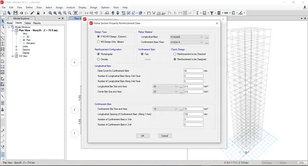
XXXIX. Similarly carry out for the column sections also
XL. In section properties now design the slab section
XLI.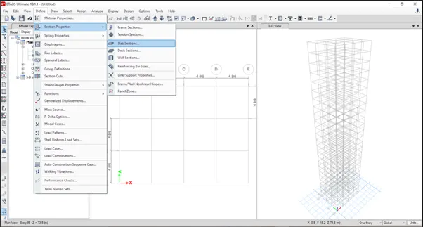
XLII. Add the new property
XLIII. Select the modelling type as the membrane
XLIV. Provide the thickness
XLV.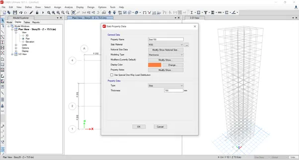
XLVI. Ok
XLVII. Select the quick draw columns
XLVIII. And place columns at the grid points for all stories
XLIX.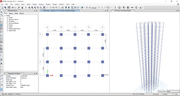
L. And select the quick draw beams all stories
LI.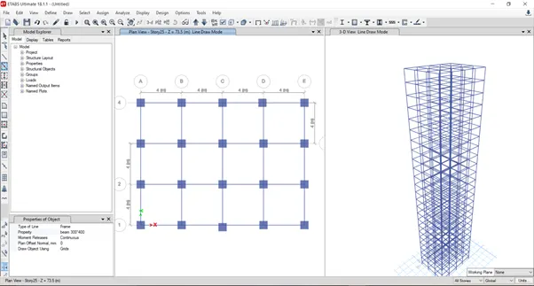
LII. Similarly, select the quick draw slabs for all similar stories
LIII.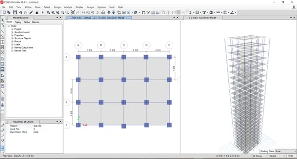
LIV. Next for one story select the grids and click on assign and click joint and restraints
LV.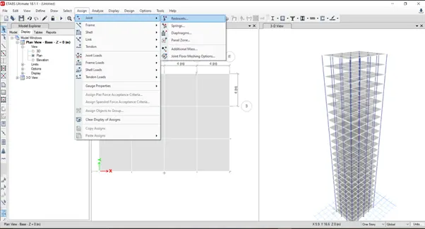
LVI. Select the point supports
LVII.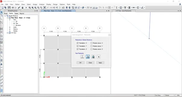
LVIII. Assign for the grid points
LIX.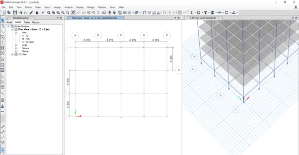
LX. Adding the load patterns
LXI. In the define select the load patterns
LXII.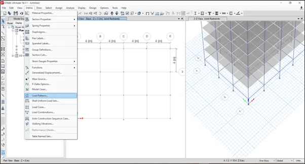
LXIII. Click on add new load and add all the required loads with the required properties
LXIV.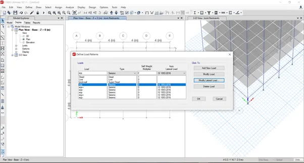
LXV. Next click on the modify lateral loads
LXVI. For every load mange the required parameters and save
LXVII. Ok
LXVIII.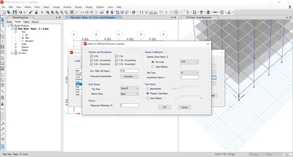
LXIX. Assign the shell loads and uniform
LXX.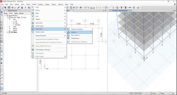
LXXI. Here live load of 3kn/m2 for all the floors rather than 1.5kn/m2 for the 25th floor
LXXII.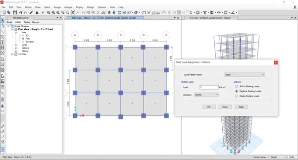
LXXIII.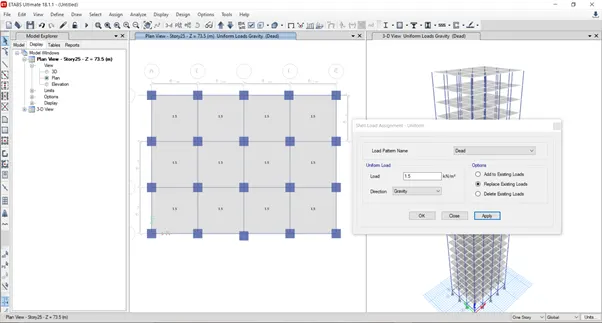
LXXIV.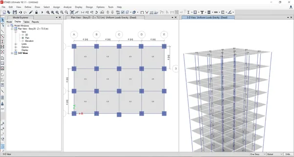
LXXV. Next assign the shell loads 1.5 only for 1 story by the replace load
LXXVI. Select all the beams by the select by object type option
LXXVII.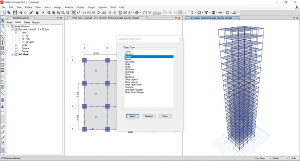
LXXVIII. Next from assign select the frame loads and distributed
LXXIX.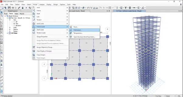
LXXX. Select the load pattern and add the load
LXXXI.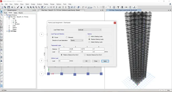
LXXXII.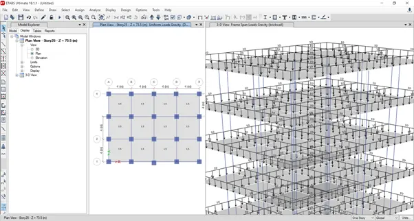
LXXXIII. In define potion select the mass source
LXXXIV. And modify
LXXXV.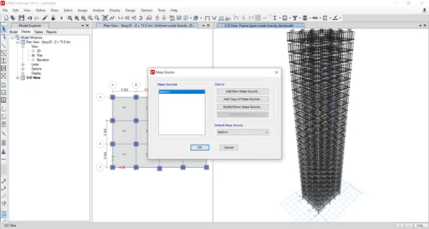
LXXXVI. Add the load patterns
LXXXVII.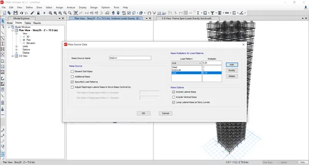
LXXXVIII. Next in the define select the load combinations
LXXXIX. Add the default design combo
XC.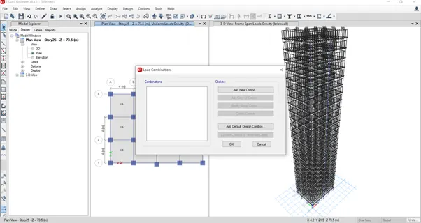
XCI. Select the concrete frame design
XCII.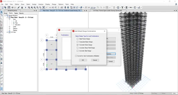
XCIII. By select object type and select the floors
XCIV.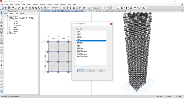
XCV. In sssign select the shell> diaphrams
XCVI.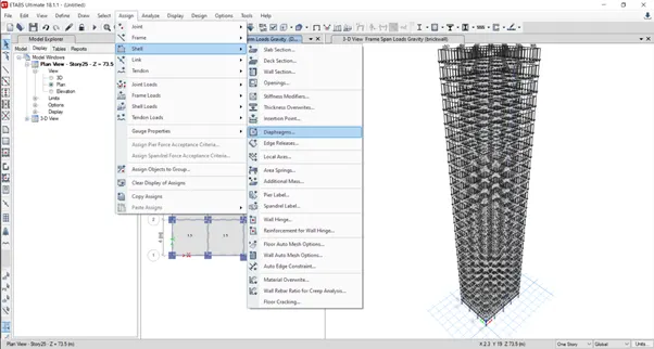
XCVII. Modify and apply
XCVIII.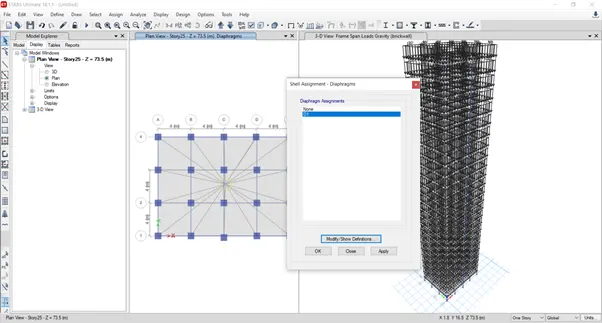
XCIX. Next the analyze click on the check model
C. And check the all the checks
CI.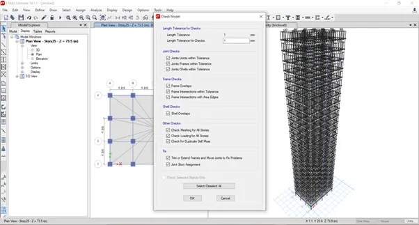
CII. ok
CIII.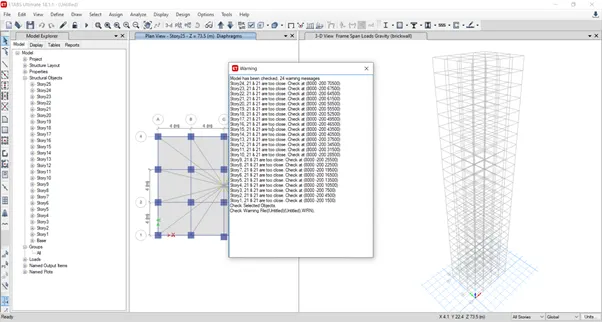
CIV. Go to design mode select the joints of the number 21 and delete
CV. Then again check the model
CVI.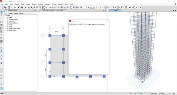
CVII. Next in analyze run the model
CVIII. Go to display> deformed shape
CIX. Deformed shape will be displayed for any particular loads
CX.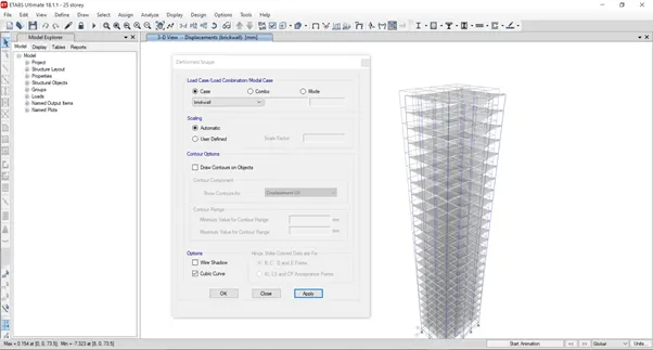
CXI.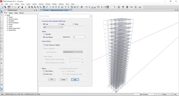
CXII.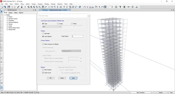
CXIII.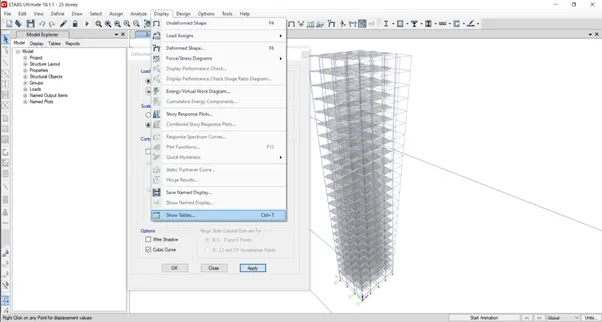
CXIV. Go to display and click on show tables
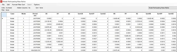
CXV. And select the modal participating mass ratio as shown in the figure below
CXVI.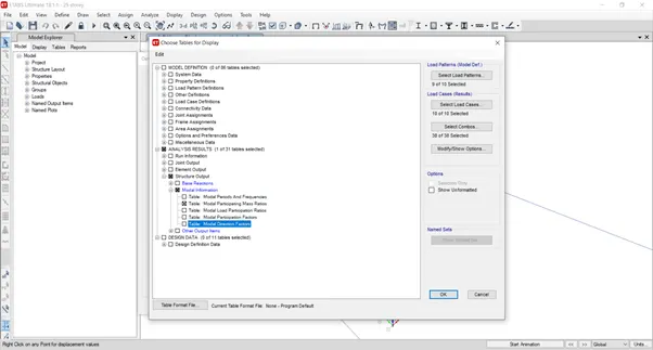
CXVII. The modal participating mass ratio table has been visible
result:
CXVIII.