Modelling and simulation of flow through a flowbench
Objective :
To create a 3D model of a flow bench and run the grid dependency test run flow analysis and obtain a plot of lift vs mass flow rate and find the effect of valve lift on the mass flow rate
About airflow bench :
An airflow bench is a device used for testing the internal aerodynamic qualities of an engine component and is related to the more familiar wind tunnel.
It is used primarily for testing the intake and exhaust ports of cylinder heads of internal combustion engines. It is also used to test the flow capabilities of any component such as air filters, carburetors, manifolds, or any other part that is required to flow gas. A flow bench is one of the primary tools of high-performance engine builders, and porting cylinder heads would be strictly hit or miss without it.
A flow bench consists of an air pump of some sort, a metering element, pressure and temperature measuring instruments such as manometers, and various controls. The test piece is attached in series with the pump and measuring element and air is pumped through the whole system. Therefore, all the air passing through the metering element also passes through the test piece. Because the volume flow rate through the metering element is known and the flow through the test piece is the same, it is also known. The mass flow rate can be calculated using the known pressure and temperature data to calculate air densities and multiplying by the volume flow rate.
Modelling :
- To model, we need a cylinder an inlet pipe and a stopper or valve lifter
- a cylinder is created by extruding a circle having a center point of the circle on the origin point
- on the perpendicular plane we draw the pathline for the inlet pump and sketch the circle perpendicular to the sketch for the inlet pipe and using sweep command we create the inlet pipe
- now using the shell command we create the thick cylinder from the completely sold geometry
- for the stopper, we use the same perpendicular plane and sketch the cross-sectional geometry of the stopper and use revolve command it to form the stopper
flow simulation for grid dependency and valve lift parametric study :
- First, create the lids for open areas
- Set the wizard and put the analysis type as internal flow and use air as fluid for the simulation
- Set the boundary condition as 2bar at inlet and 1 bar at the outlet
- select the velocity cut plot for the result
- create the new parametric study and put the input parameter as the level of mesh and output parameter as the cut plot
- we are testing for the level of a mesh of 4,5 and 6
- after the results, we choose the best suitable level of mesh for further study
- create the new parametric study for the effect of valve lift on the mass flow rate
- for the input parameter, we use the dimension and for output, we select the mass flow rate
- we are testing for the valve lift of 1mm to 10mm
Results :
- Grid dependency test for level of the mesh of 4,5 and 6 respectively
From the results, we see clearly that from the 6th level of mesh we are getting the most accurate results therefore for further study we use the 6th level of mesh
- Valve lift vs mass transfer study
At 12 mm of the lift where the mass flow rate becomes nearly constant
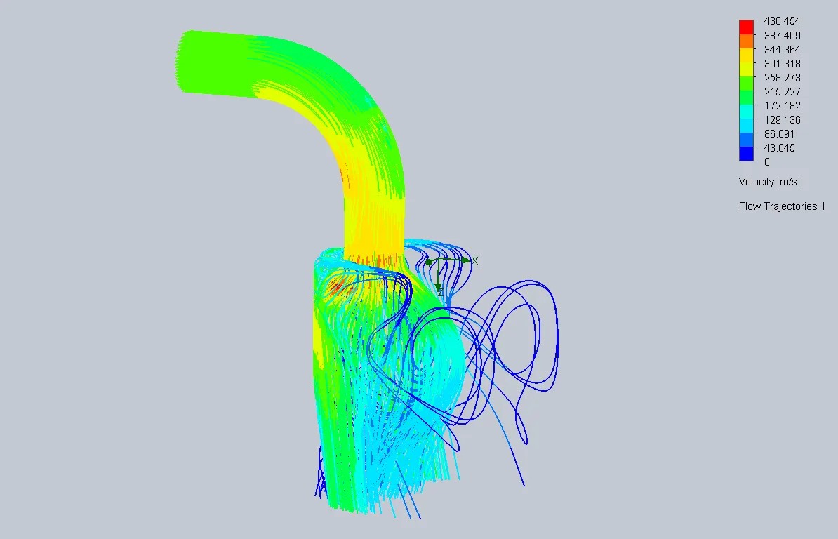
Animation video: https://youtu.be/gYgeAtOZRAo
conclusion :
From the graph, we can say that after some 10mm of lift the mass flow rate became nearly constant.