AIM:
To create a 3D model of a flow bench and run flow analysis, plot lift vs mass flow rate, and perform grid dependence test.
THEORY:
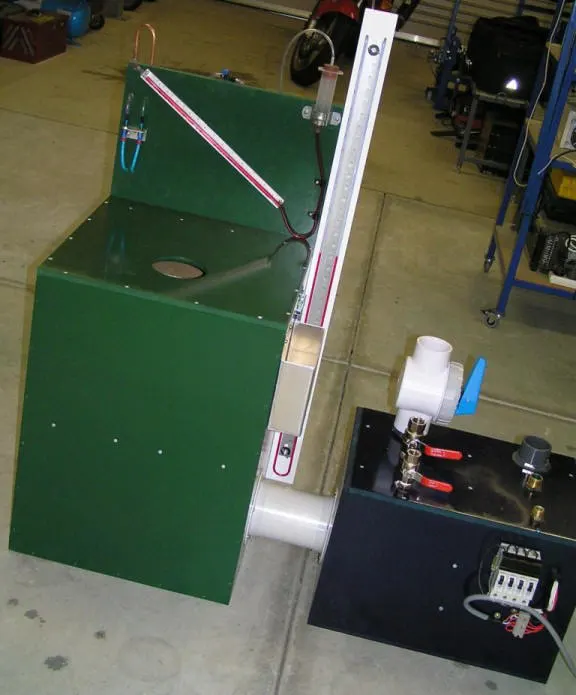
An Air-Flow Bench is a device that measures the volume or mass of air that will pass through a bounded path or conduit in relation to an applied pressure differential. The pressure differential is usually relative to ambient air pressure and is often produced by some mechanical means such as an electric blower or at least one electric vacuum motor. The flow bench air source creates a pressure differential across the test object that causes air to flow through not only the test object but through the entire flow bench. At some point in the flow bench, the airflow velocity is measured. From the measured air velocity, the volume or mass of air that is flowing through the test object can be calculated.
A flow bench with an air source that can apply a pressure differential to the object being flow tested is referred to as an active flow bench. A passive flow bench has no air source, the object being tested supplies its own pressure differential to promote measurable airflow, such objects would be electric blowers or fans and vacuum motors.
It is often believed that flow benches are only used for flow testing internal combustion engine cylinder heads, but in fact, many other items like carburetors, intake manifolds, exhaust manifolds, turbocharger housings, air filters, pneumatic couplings and fittings, AC grills and condensers, and nozzles of different types often find their way onto a flow bench. Early flow benches were mostly used to test aircraft carburetors.
The pressure differential applied to the test object is important to know since airflow is relative to the applied pressure differential.
FLOW SIMULATION SETUP:
1. Open SolidWorks. Open a new Part Design Model.
2. In the Top Plane, draw a circle of radius 0.05m. Exit sketch and extrude the circle by 0.1m.
3. In the front plane Draw an intersecting pair of horizontal and vertical lines and fillet it by radius 0.04m. This will be the axis of the port.
4. Select Features ---->Reference Geometry -----> Plane. Select Line and Point as Reference. Plane 1 is created.
5. In the new plane, sketch a circle of radius 0.0125m. Exit Sketch, and use the Swept Boss/Base
option. The port is created.
6. To create the axis of the valve, select Reference Geometry---->Axis. For reference select the vertical portion of the port. Axis is created.
7. To Create Plane of Valve, Select Reference Geometry--->Plane. Select References as the axis just created and the right plane. The plane is created.
8. Select the plane, and sketch the profile of the valve. Make the dimensions, exit sketch, and use the revolve function. Uncheck the merge with the sketch option.
9. The model is now ready. Select the shell command and make the Flow Bench Hollow by selecting the inlet and outlet face. Thickness is 0.001m.
10. Click On Flow Simulation, Select The Wizard option. Enter a project name. Under type of flow, select external. It is a transient flow with total analysis time as 0.1s and Output Step time as 0.01s. Under the type of fluid, choose air. Under Velocity in X-direction, enter 10m/s. Click Finish.
11. Computational Domain is created.
12. Set Boundary Conditions. Total Pressure of 3 bar( 303975 Pa) at the inlet face and static pressure of 101325 Pa(1 bar).
13. Set Global and Local Goals, with the parameter being mass flow rate. For surface to be selected under Local Goals, choose the outlet face (LID 2).
14. Right Click Mesh, select Insert Local Mesh. Under faces to be selected, select the faces of the valve and make it to value 6. Right-click Global Mesh and select Edit Mesh. Make the grid size 3 and run the simulation. Select
View-->Goal Plot. Under Parameter, select SG Mass Flow rate. The curve will appear. Wait for the goals to converge. Stop the iterations and close the simulation. Similarly, run the simulation for grid size 4 and 5 and compare.
15. After running the simulation, create 2 Cut-plots in the top-plane with parameters as Pressure and Velocity respectively. Compare the Cut-plots.
Pressure Cut-plots:
Mesh Grid Size 3
Mesh Grid Size 4
Mesh Grid Size 5
Velocity Cut-plots:
Mesh Grid Size 3
Mesh Grid Size 4
Mesh Grid Size 5
Size 5 is not selected as the computational time is too large and 3 is not chosen because its accuracy is low. Hence Size 4 is selected.
CREATING FLOW TRAJECTORY:
16. After Running Simulation for grid size 4, Go To Results---->Flow Trajectory----->Insert.
17. Under Faces to select, select the inlet and outlet face. Keep the number of points as 20.
PARAMETRIC STUDY:
18. To find the relationship between mass flow rate and valve lift, a new Parametric study has to be created. Under Input Variables, select Geometric Parameters and click on the valve lift dimension. Set 10 values of valve lift (1mm to 10mm).
19. Under Output Parameters, select SG Mass flow rate as a result and the Cut-plots as goals.
20. Go to Scenario and click Run.
RESULTS:
Cut Plot 1(Pressure):
0.001m 0.002m
0.003m 0.004m
0.005m 0.006m
0.007m 0.008m
0.009m 0.010m
Cut Plot 2 (Velocity):
0.001m 0.002m
0.003m 0.004m
0.005m 0.006m
0.007m 0.008m
0.009m 0.010m
Variation of Mass Flow rate with respect to Valve Lift:
INFERENCE:
1. From the Velocity goal plot, we infer that that with an increase in valve lift, the inlet velocity increases.
2. From the Goal Plot, we infer that as valve lift increases, the mass flow rate also increases, but with a negative slope. After a point, the valve lift will have little effect on the mass flow rate.
3. After 8 iterations, the rate of increase in mass flow rate is very less.
SOURCES: