Modelling and simulation of flow through a flowbench
Flow bench Simulation
Aim
To perform a flow bench simulation for different mesh grid size to select the best grid and check the velocity and pressure plots for every valve opening from minimum opening to maximum opening for mass flow rate.
Design Specifications
Diameter of cylinder = 100mm
Length of cylinder = 100mm
Diameter of pipe = 25mm
Thickness of cylinder = 2mm
Minimum valve lift = 1mm
Maximum valve lift = 8mm
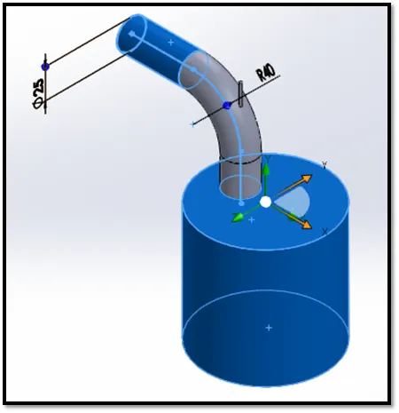
Simulation Parameters
Simulation type = Steady state
Medium = Air
Flow type = Internal
Velocity = 10m/s
Pressure = 101325Pa
Procedure
- Design the cylinder and valve according to the design parameters and provide lids to both the opening ends to perform the internal flow simulation.
- Activate the flow simulation and insert the parameters for steady state simulation.
- Perform the grid dependency for various mesh grid sizes and select the suitable one.
- Assign local and surface goals for mass flow rate.
- Run the simulation and check results for Velocity and pressure plots for every valve opening.
Grid dependency test
TEST1: Mesh grid size = 3
TEST2: Mesh grid size =4
TEST3: Mesh grid size =5
Result plots
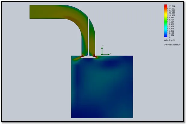
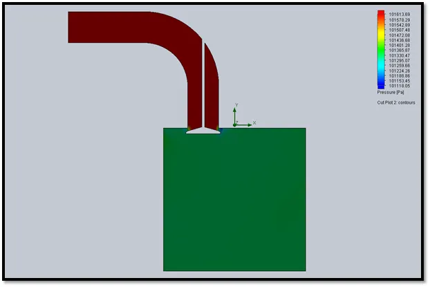
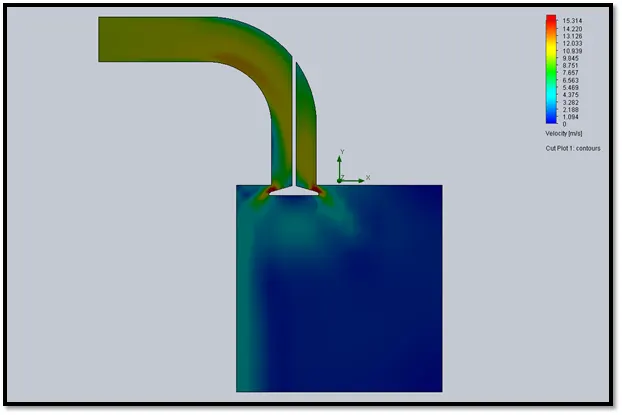
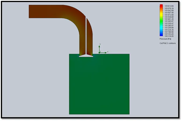
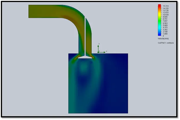
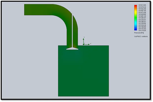
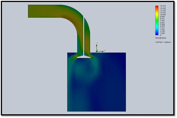
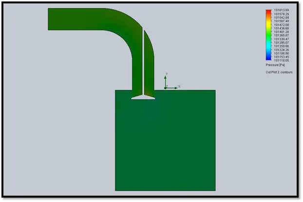
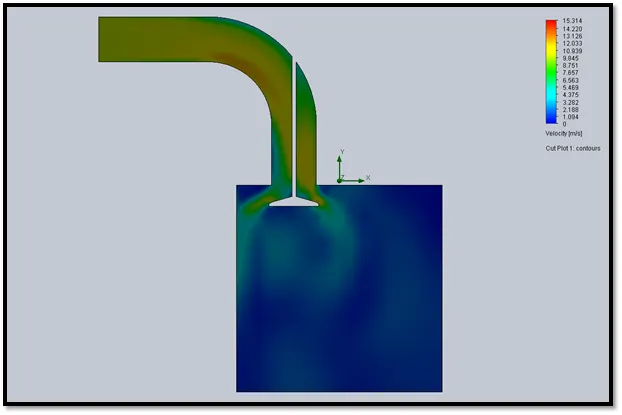
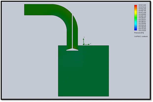
A parametric study is done for eight values of valve lift from 1mm to 8mm and velocity and pressure plots are generated.
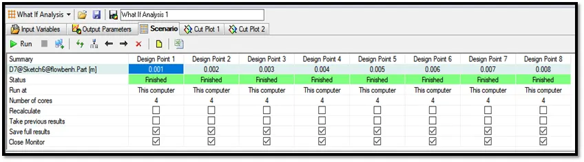
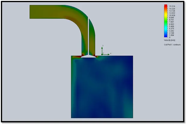
Case 1: Valve lift of 1mm
Velocity plot
Pressure plot
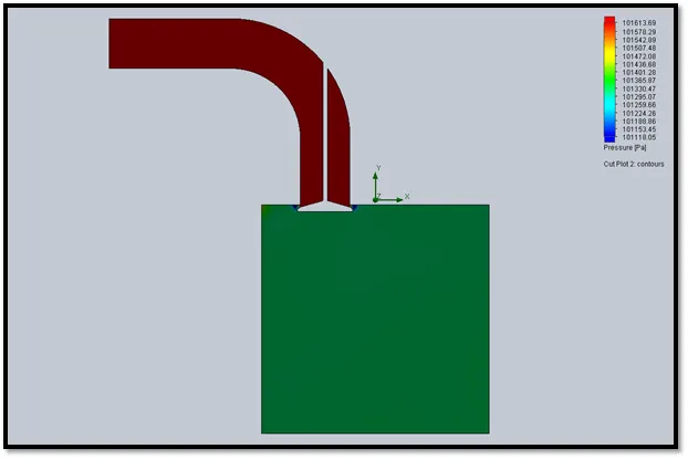
Case 2: Valve lift of 2mm
Velocity plot
Pressure plot
Case 3: Valve lift of 3mm
Velocity plot
Pressure plot
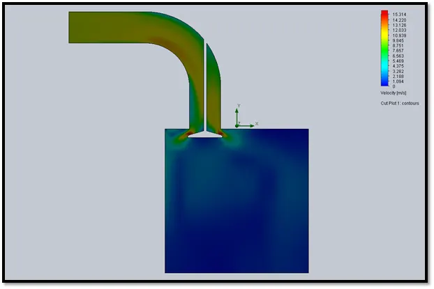
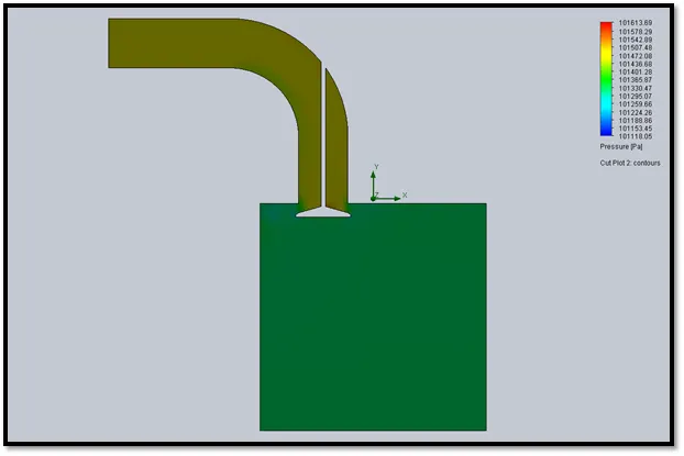
Case 4: Valve lift of 4mm
Velocity plot
Pressure plot
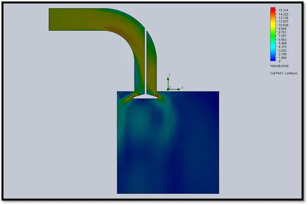
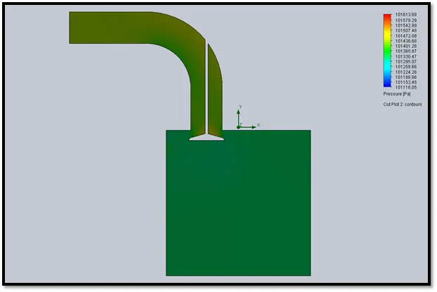
Case 5: Valve lift of 5mm
Velocity plot
Pressure plot
Case 6: Valve lift of 6mm
Velocity plot
Pressure plot
Case 7: Valve lift of 7mm
Velocity plot
Pressure plot
Case 8: Valve lift of 8mm
Velocity plot
Pressure plot
Conclusion
The above simulation study shows as the air starts entering the cylinder the velocity increases and pressure decreases. As the inlet, port size increases the velocity decreases and thus pressure decreases. The finer grid size gives the best results.