Modelling and simulation of flow through a flow bench by using SOLIDWORKS
AIM :
To create a 3d model of flow through a flowbench, run a simulation of grid dependency test and Valve lift dependency test.
FLOW OF CONTENT/METHODOLOGY :
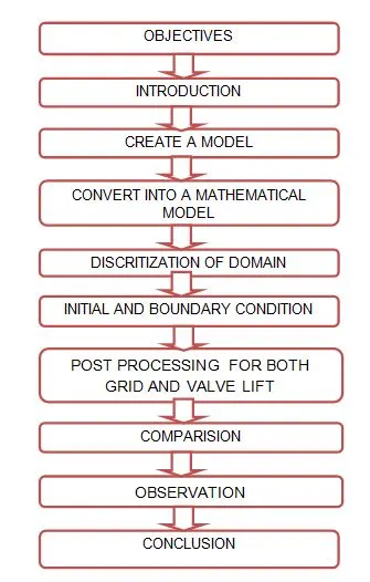
OBJECTIVES :
1) To make a engine cylinder and inlet chamber with one piece poppet type valve.
2) Run the new parameter simulation for three different grid size with fixed valve lift.
3) Run the another new parameter simulation for seven different valve lift with fixed mesh grid size.
4) Plot the variation of mass flow rate at each and every valve lift.
INTRODUCTION :
Computational fluid dynamics is a science that, with the help of digital computers, produces quantitative predictions of fluid flows phenomena based on Navier stroke equation is consists of conservation laws such as time dependent continuity equation for conservation of mass, three time dependent conservation of momentum equation and a time dependent conservation of energy equation.
Air flow bench :
An air flow bench is a device used for testing the intake port of an engine, it means predicts the aerodynamic qualities like flow velocity, pressure, density, compressibility and viscosity. Not only for inlet port, it is also used to test the flow capability of any component such as air filters, carburetors, manifolds or any other part that is required to flow gas. It is used primarly for testing the intake and exhaust ports of cylinder heads of internal combustion engines. In our case, we only concern the pressure, velocity variation along the intake port chamber with distinct parametric studies.
Valve lift :
The valve lift is the distance by which valve is raised from its seated position when it is fully opened. These valve spring allow a maximum valve lift only. The camshaft controls the speed of valve opening, valve lift off the valve seat and how long the valve stay open. The valve lift height and duration corresponds to the height and shape of the valve lobes.
Poppet valve :
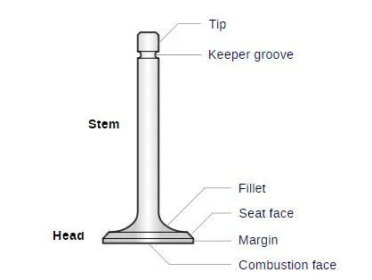
A poppet valve is also called as mushroom valve is a valve typically is used to control the timing and quantitiy of gas flow or vapor flow into an engine. It is consists of hole usually round or oval and a tapered plug, usually a disk shape on the end of a shaft also called a valve steam. The protion of the hole where the plug meets with it is called the "seat" or "Valve seat". The shaft guides the plug portion by sliding through a valve guide. In exhaust applications a pressure differential helps to seal the valve and in intake valves a pressure differential helps open it.
CREATE A MODEL :
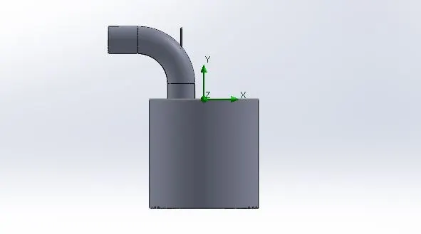
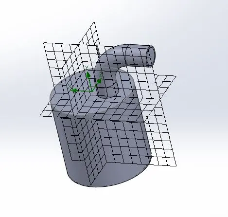
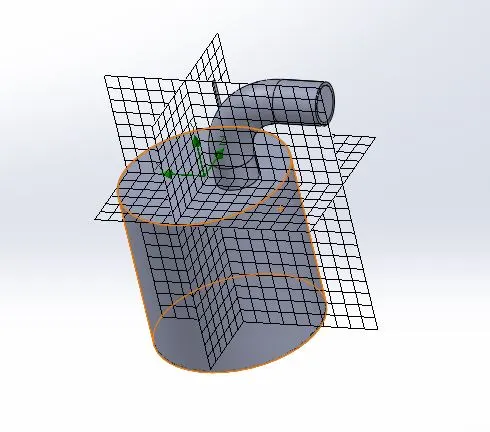
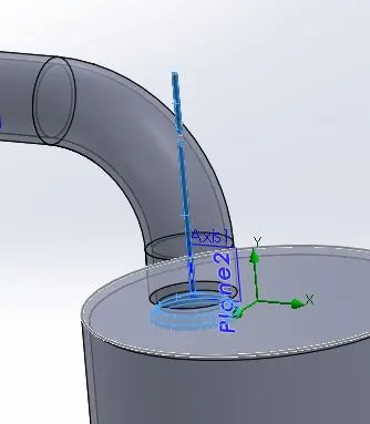
Create a circle with appropriate dimension and extrude it, create a referance plane to make a path and profile sketch for buliding the intake chamber. Use the shell, converting from solid body to hollow with providing appropriate dimensions. Sketch the valve and revolving about the referance axis.
Model Dimensions :
Diameter of cylinder = 0.05 m
Length of a cylinder = 0.1 m
Diameter of a pipe = 0.025 m
Shell thickness = 0.002 m
CONVERT INTO A MATHEMATICAL MODEL :
Wizard Analysis Type :
Unit system - SI
Flow type - Internal
Physical feature :
Time dependent
Total analysis time - 5 second
Output time step - 1 second
Working fluid - Air
Pressure - 101325 pascals
Temperature - 293 K
DISCRITIZATION OF DOMAIN :
The process of discritize the mathematical domain is divided into finite cells or elements is called meshing. The whole constrainted domain is splited into small piece, the governing eqaution is solved in each and every element or cell.
Level of grid size is 2
Element type = Hexahedral
Total cells = 1356
Fluid cell contacting solids = 868
When we increase the refinement of mesh, the final result is almost close to exact results. The error is inversely proportional to calculating time when we increase the refinement grid size value.
The error is high, a calculation time is less
The error is low, a calculation time is high.
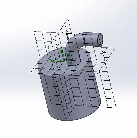
Level of grid size is 3
Element type = Hexahedral
Total cells = 3951
Fluid cell contacting solids = 2169
Level of grid size is 4
Element type = Hexahedral
Totals cells = 8758
Fluid cell contacting solids = 3857
Refining the fluid cells near the valve :
Refining the fluid cells contact with valve, 3 times finer than automatic mesh.
INITIAL AND BOUNDARY CONDITIONS :
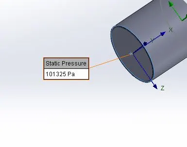
Inlet pressure is 2 times higher than the atmospheric pressure, the value is 202650 in pascals this is a total pressure. The total pressure is a sum of static pressure and dynamic or velocity pressure and graviational potential energy per unit volume.
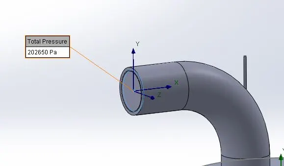
The outlet is set to be in static pressure, it value is eqaul to atmospheric pressure.
POST PROCESSING :
Grid dependency test :
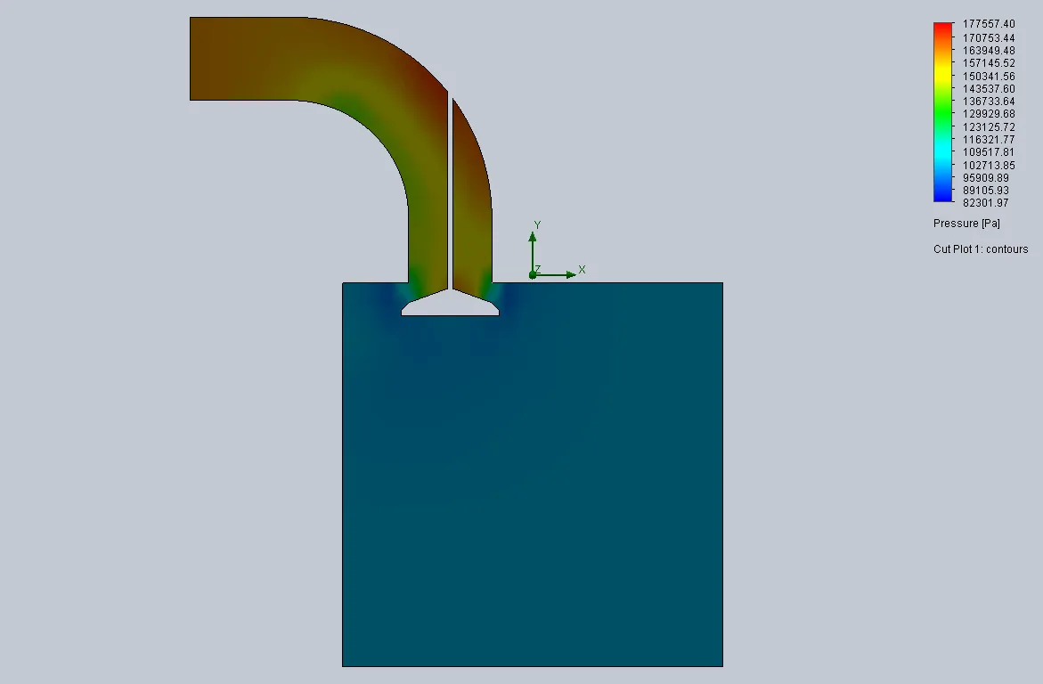
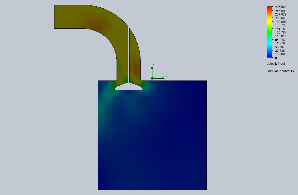
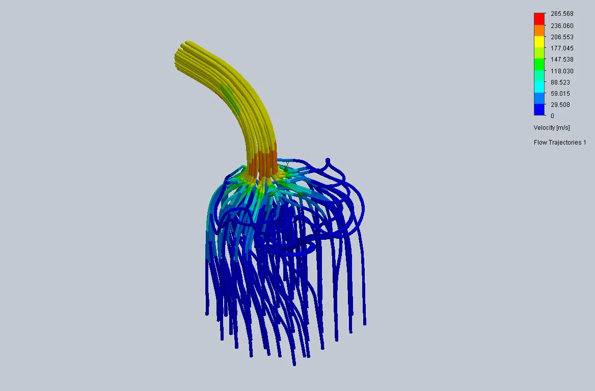
1) Create a new parametric study, add the simulation parameter of global automated mesh 2,3 & 4 in additionally we focus on mass flow rate along the domain, In this case, we concern only Pressure, velocity and flow trajectories from inlet to outlet.
2) To fix the valve lift distance for all cases in grid dependency test.
3) For each level of mesh, the grid element is increased, results accuracy is also increased. But, when we increased the grid size, calculating time span is always increased.
Case 1
Mesh grid size 2
Pressure contour for grid size 2
Velocity contour for grid size 2
Flow trajectories for grid size 2
Case 2
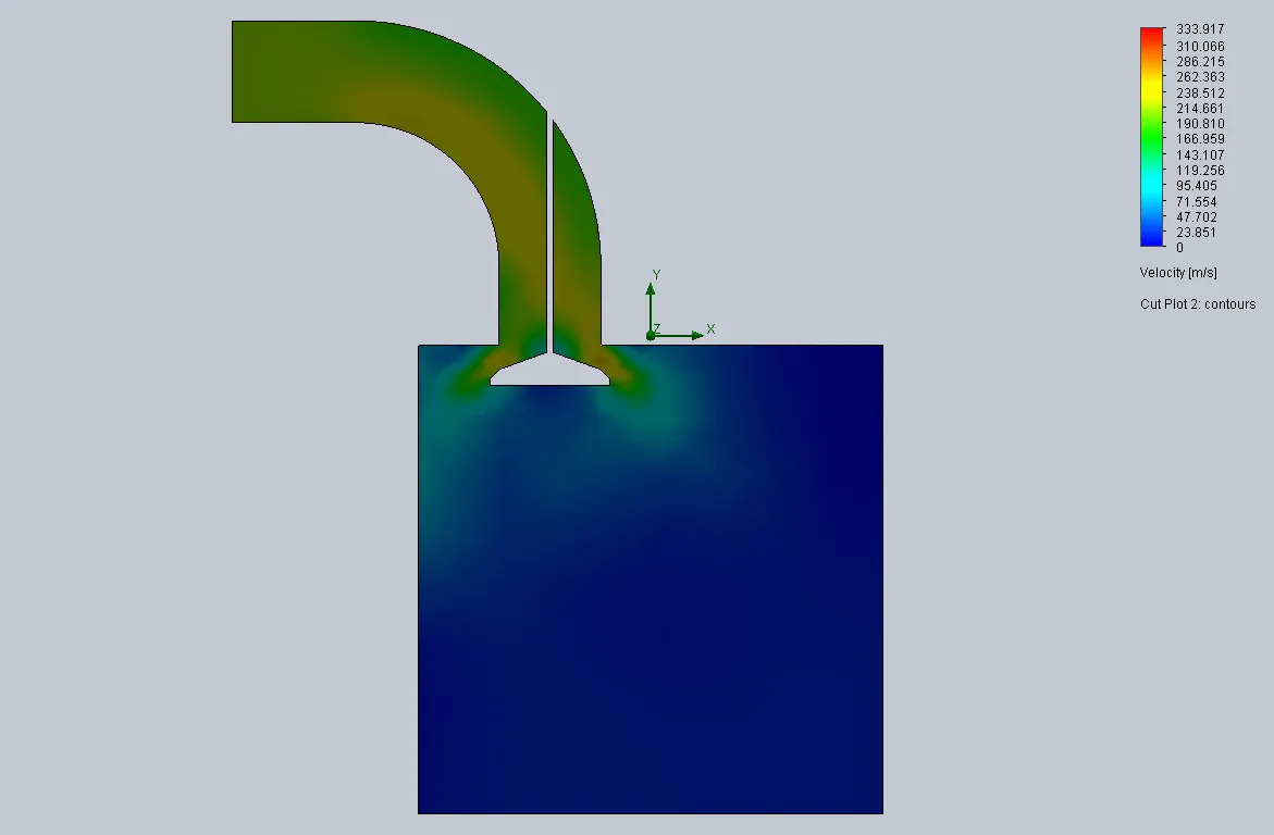
Mesh grid size 3
Pressure contour for grid size 3

Velocity contour for grid size 3
Flow trajectories for grid size 3
Case 3
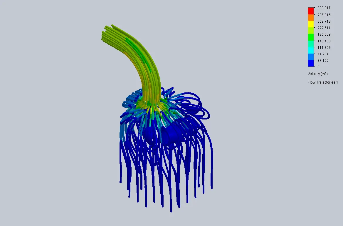
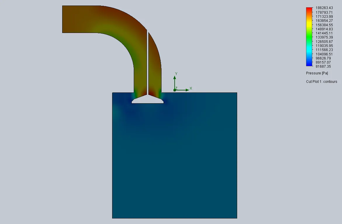
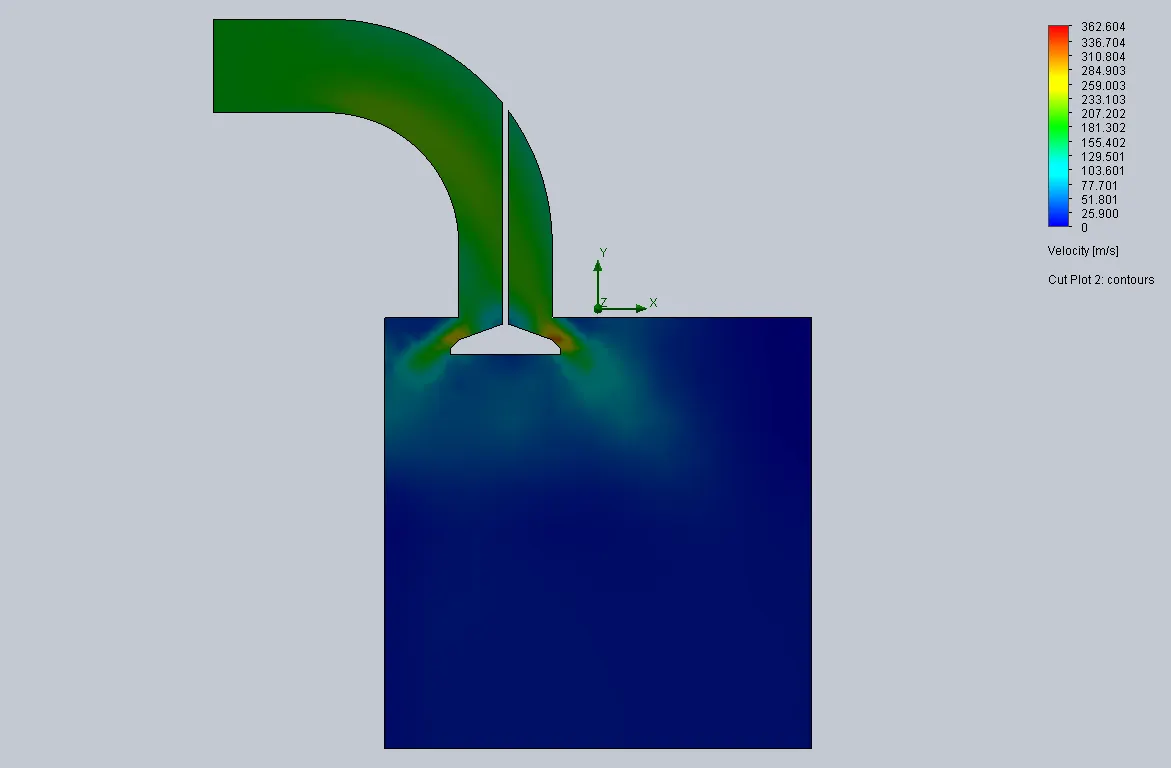
Mesh grid size 4
Pressure contour for grid size 4
Velocity contour for grid size 4
Flow tracjectories for grid size 4
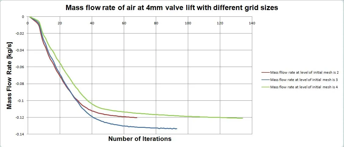
Mass flow rate converging over the iteration for different grid sizes with fixed 4 mm valve lift :
Goals for different grid sizes

Valve lift dependency test :
We decide the grid size 4 is best compared to 2 & 3 grid sizes. To fix the grid size 4, run the parametric study for different valve lift in range of 1 mm to 10 mm with seven intervals. Create a parametric study, select the dimensions between the valve seat edge and inner face of the cylinder, automate it for increasing the valve lift from 0 to 10 mm.
Case 1 :
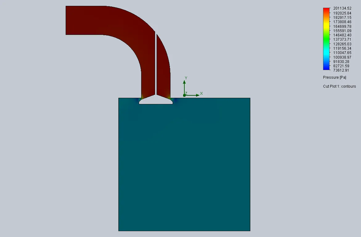
Pressure contour for 1 mm valve lift :
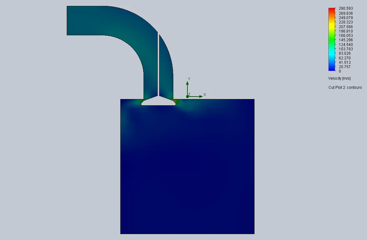
Velocity contour for 1 mm valve lift :
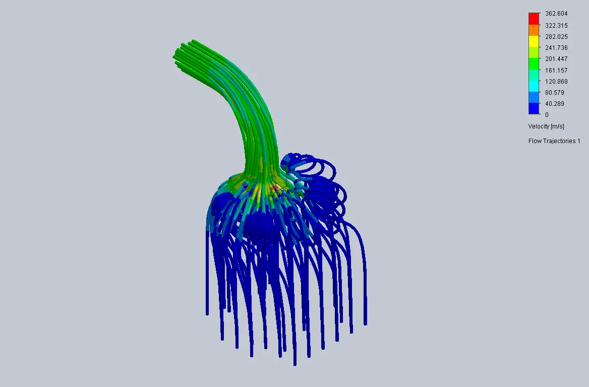
Flow trajectories for 1 mm valave lift :
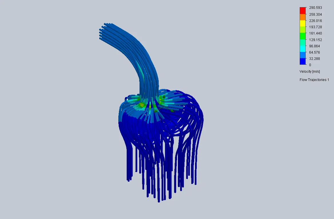
CASE 2
Pressure contour for 2.5 mm valve lift :
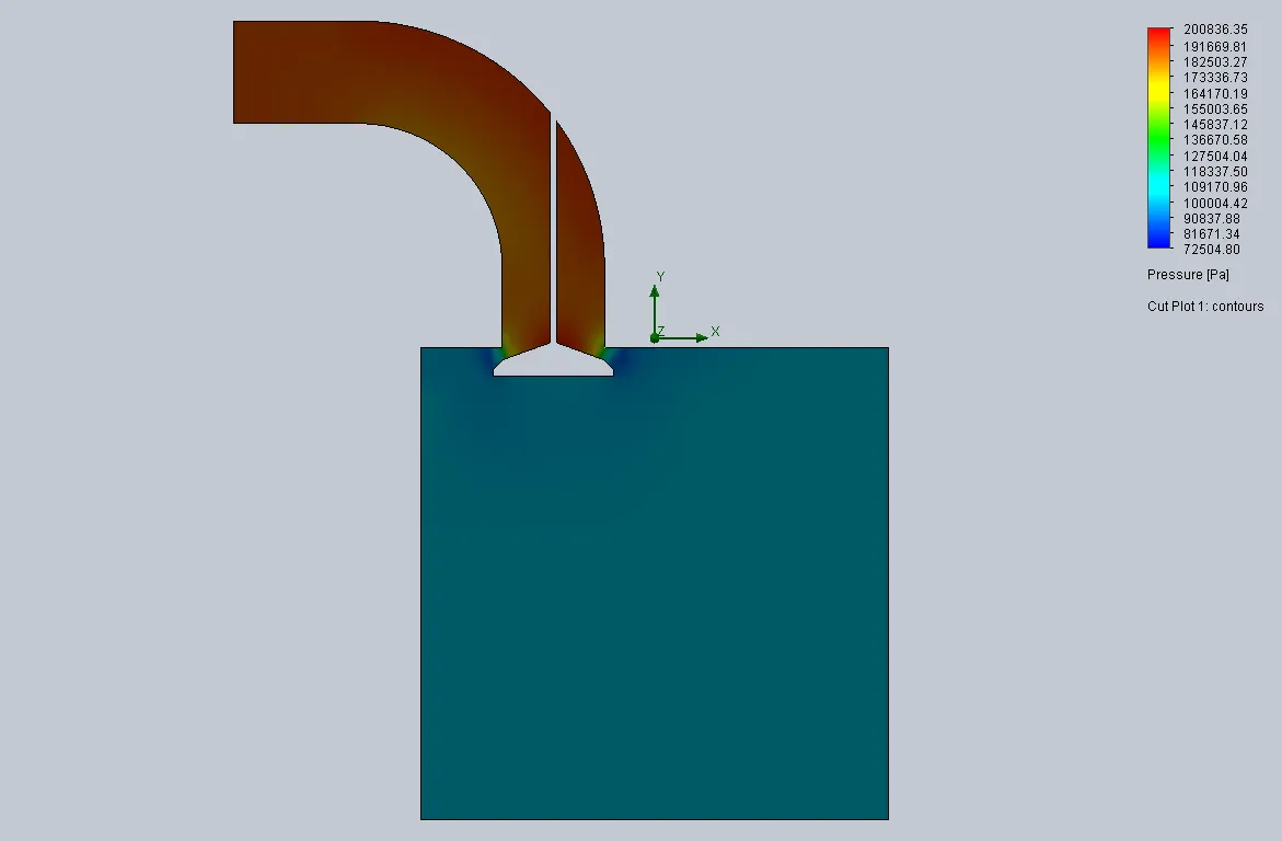
Velocity contour for 2.5 mm Valve lift :
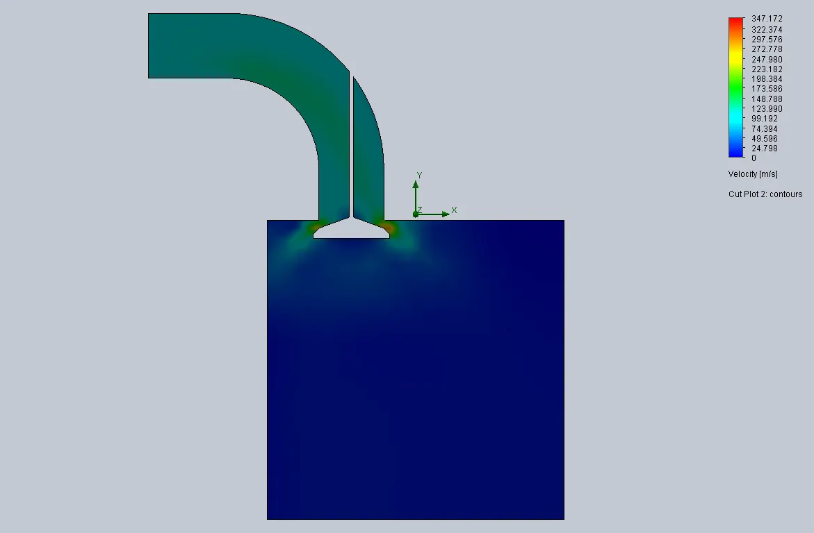
Flow trajectories for 2.5 mm valve lift :
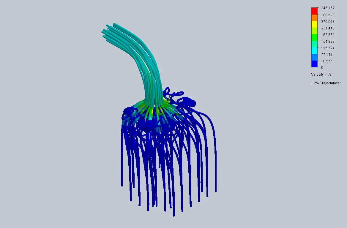
CASE 3
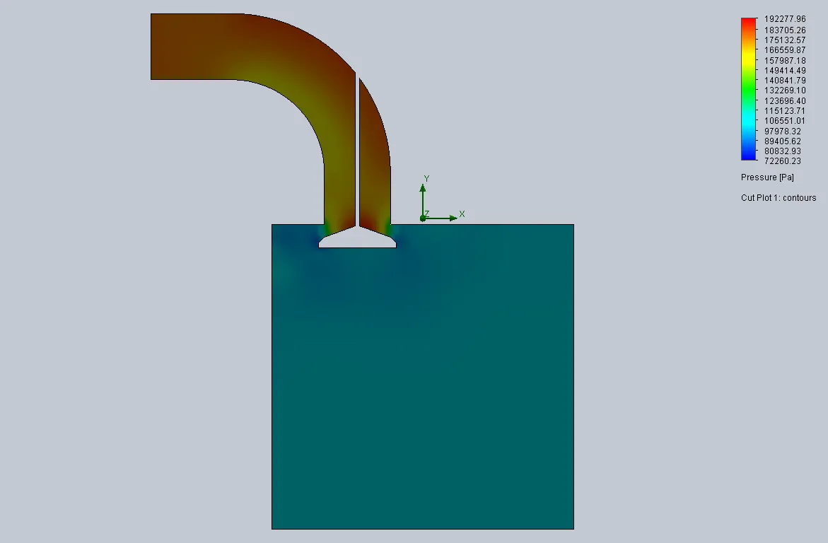
Pressure contour for 4 mm valve lift :
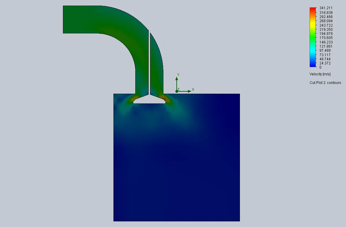
Velocity contour for 4 mm valve lift :
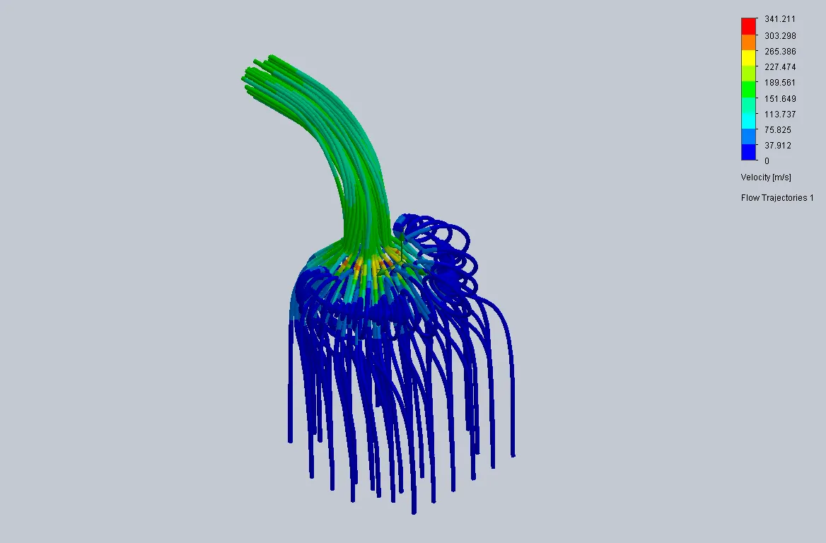
Flow trajectories for 4 mm valve lift:
CASE 4
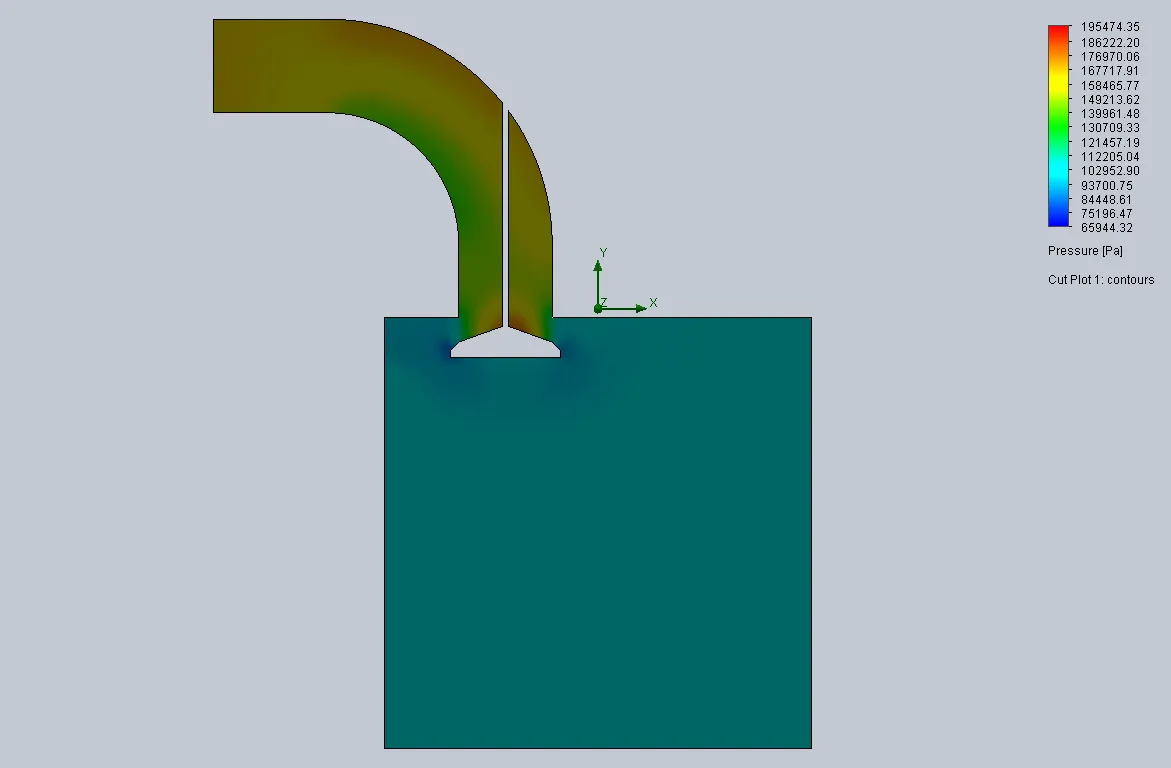
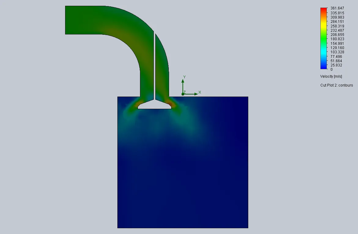
Pressure contour for 5.5 mm valve lift :
Velocity contour for 5.5 mm Valve lift :
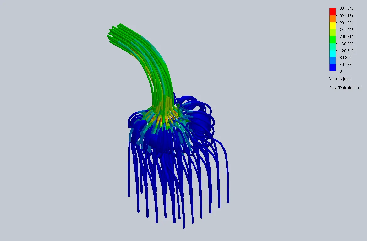
Flow trajectories for 5.5 mm valve lift :
CASE 5
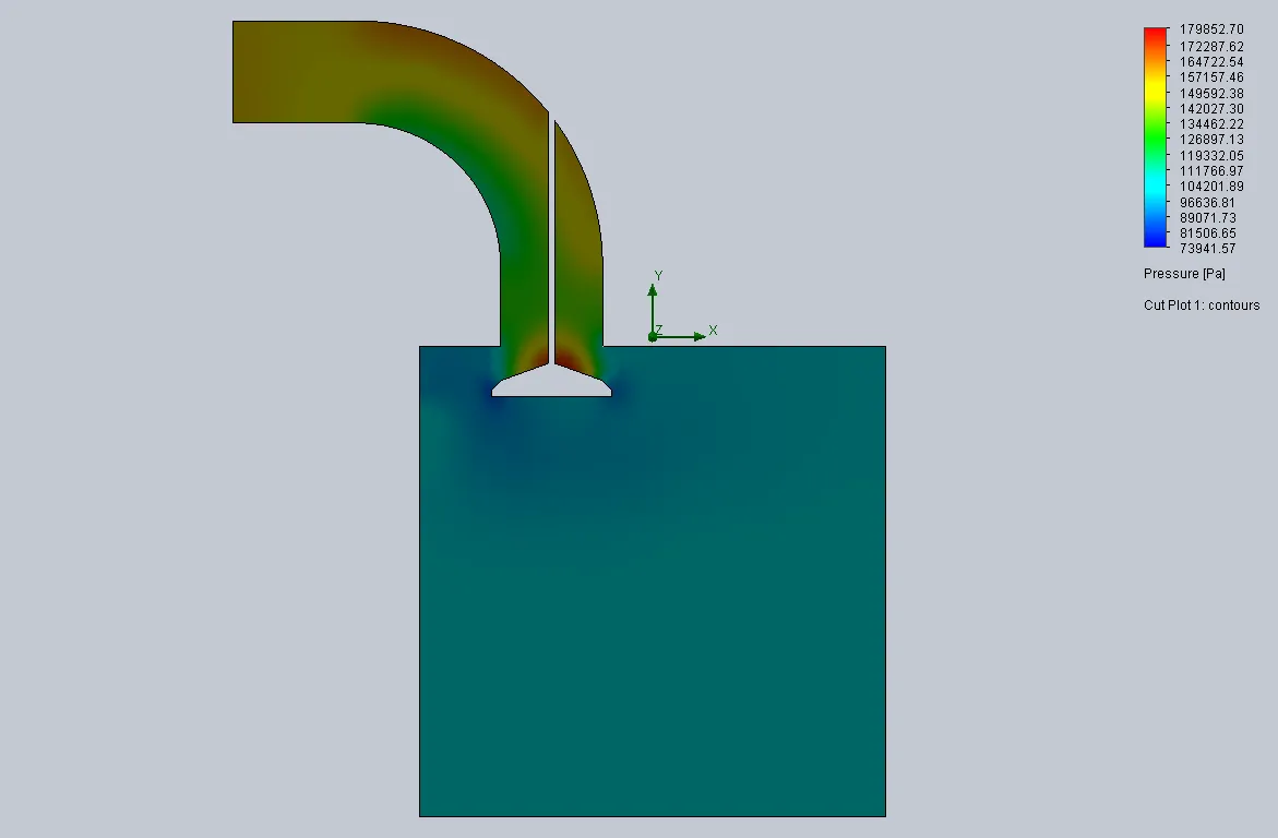
Pressure contour for 7 mm Valve lift :
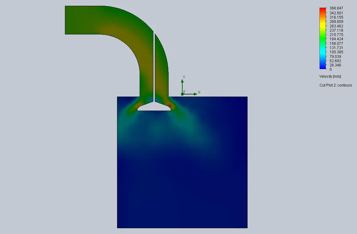
Velocity contour for 7 mm Valve lift :
Flow trajectories for 7 mm Valve lift :
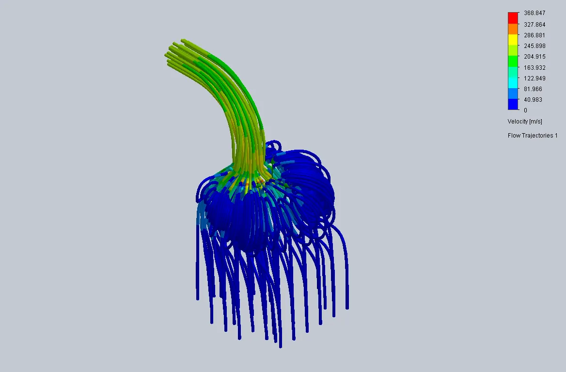
CASE 6
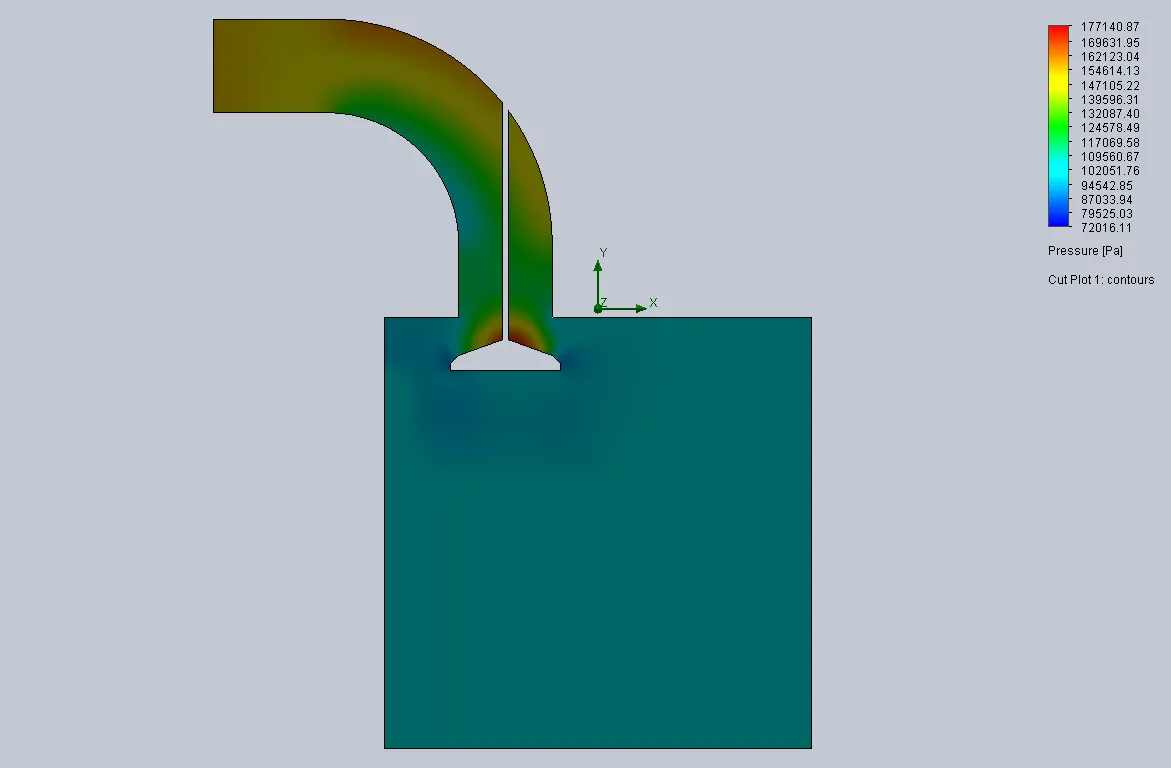
Pressure contour for 8.5 mm Valve lift :
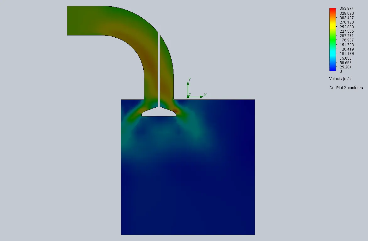
Velocity contour for 8.5 mm Valve lift :
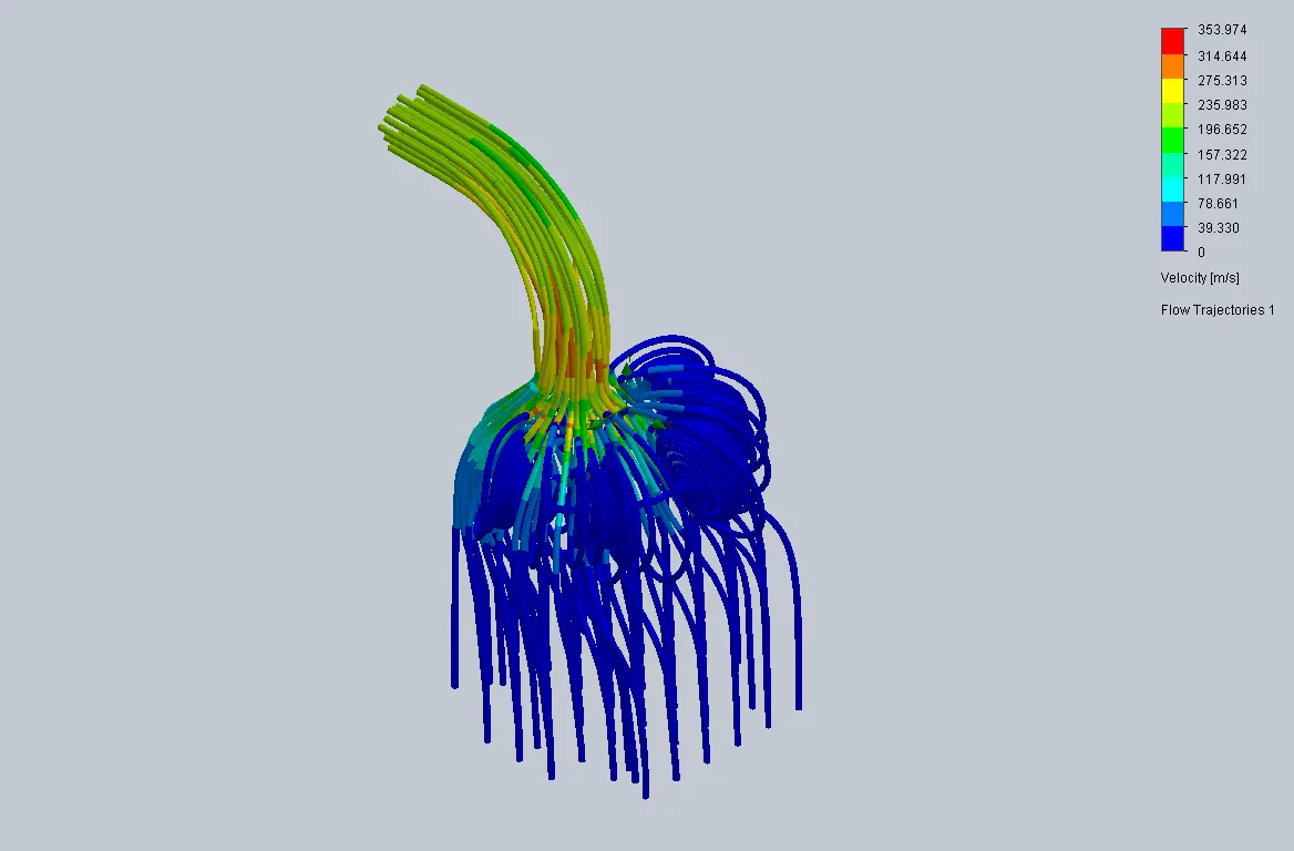
Flow trajectories for 8.5 mm Vlave lift :
CASE 7
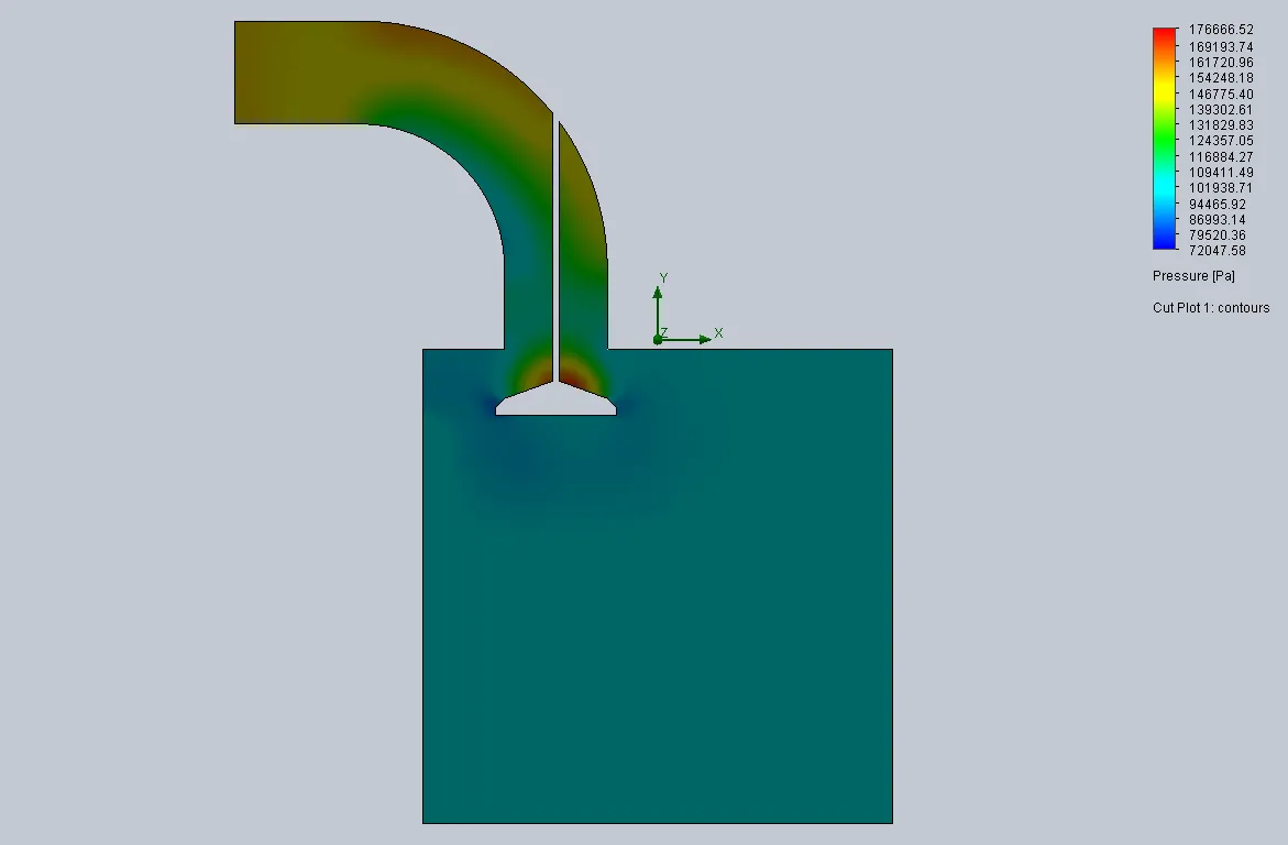
Pressure contour for 10 mm valve lift :
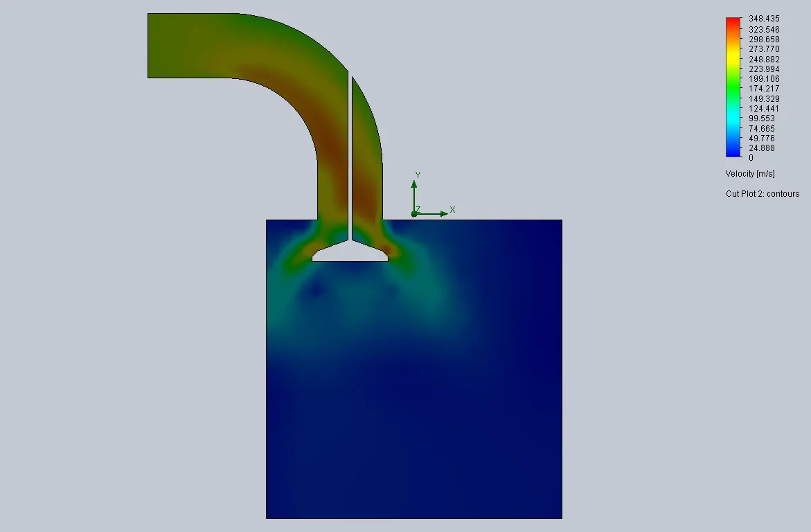
Velocity contour for 10 mm Valve lift :
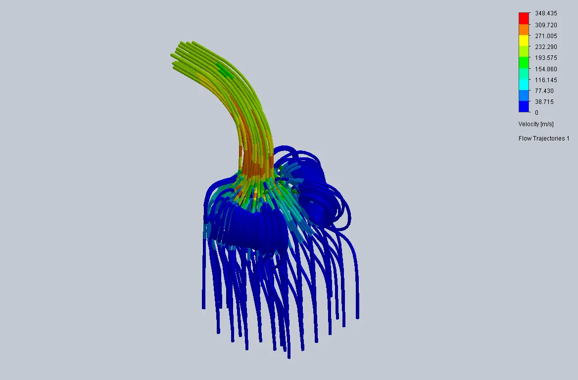
Flow trajectories for 10 mm valve lift :
COMPARISIONS :
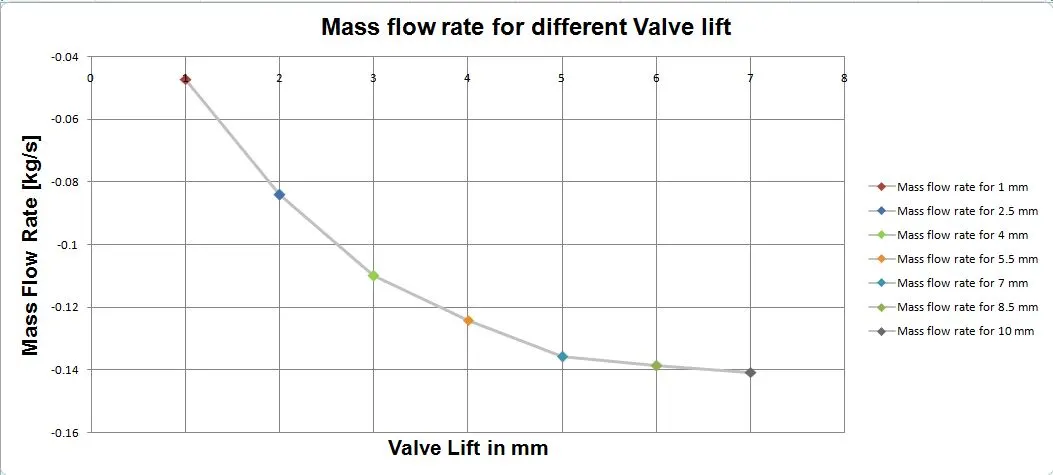
Mass flow rate for different valve lift
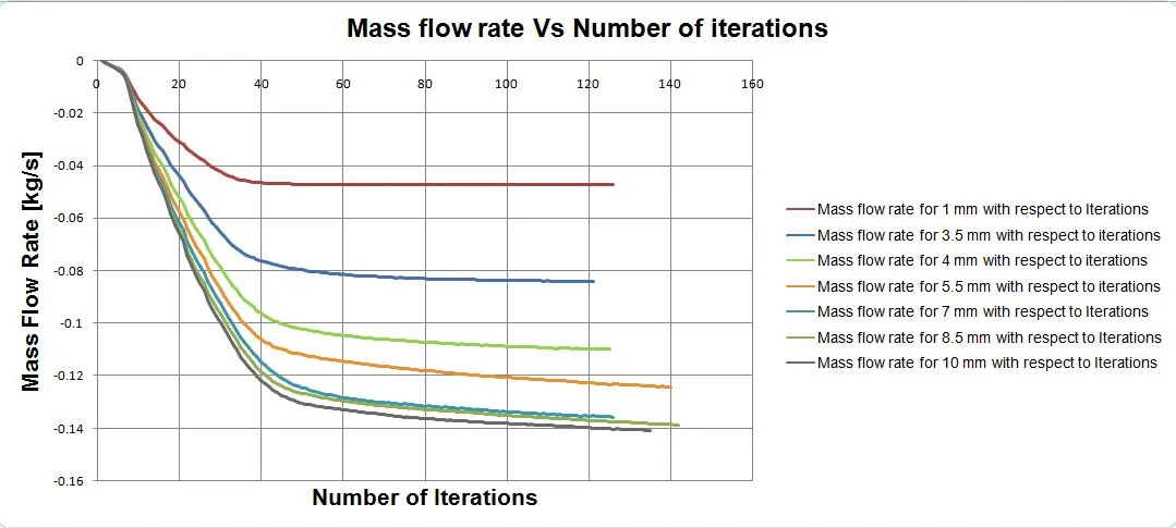
Mass flow rate is continuously increasing when we increase the valve lift opening. The Negative sign indicates, the mass flow rate is exit from the domain.
Mass flow rate Vs Iteration for different valve lift :
OBSERVATION :
1) In the grid dependency test, the mesh refinement has increased when we increase the level of initial mesh. The mesh grid size 4 output is more accuracy than the mesh grid size of 2 & 3 with fixed valve lift 4mm.
2) We can easily visualize the results accuracy for different grid sizes from the contours.
3) Mass flow rate is increased when we increased the valve lift opening. As we increase the valve lift, the pressure has to be droped proportional to valve lift and velocity is increased. In this cases, the bernoullie's principle satisfied.
4 )Over the period, mass flow rate is neglegibly variation from valve lift 8.5 & 10 mm.
CONCLUSION :
Finally , ran the simulation for grid dependency test with fixed valve lift and Valve lift dependency test with small grid size for all the cases. Final results are acceptable thing and it satisfied the bernoullie's principle.
REFERANCE :