Modelling and simulation of flow through a flowbench
Aim:- To create a 3D model of a flow bench and run flow analysis and plot lift vs mass flow rate.
Theory:-
The internal combustion (IC) engine is designed to produce power from the energy that is contained in its fuel and for the fuel to burn air(oxygen) is necessary. The quantity of air(oxygen) decides the quantity(power) and the quality(exhaust gases) of the combustion process. Airflow rate depends on the geometry, size of inlet port and the inlet valve design. Flowbench is a device which helps us to understand how the fluid flows inside the cylinder through inlet port and valve to find the mass flow rate.
An air flow bench is a device used for testing the internal aerodynamic qualities of an engine component and is related to the more familiar wind tunnel. It is used primarily for testing the intake and exhaust ports of IC engines. It is also used to test the flow capabilities of any component such as air filters, carburetors, manifolds or any other part that is required to flow gas. A flow bench is one of the primary tools of high performance engine builders, and porting cylinder heads would be strictly hit or miss without it.
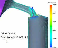
Procedure of simulation:-
1. A cylinder with a bore of 0.1m, stroke length of 0.1m, an inlet valve of suitable dimension and its conveted into shell and lids are created in solidworks.
2. Boundary conditions and goals are set. And the mesh is created.
3. First grid dependency test is done to get best grid and then with the best grid we run a parametric sweep to show the effect of valve lift on mass flow rate.
Results:-
Grid dependency test:
Effect of valve lift on mass flow rate:
Conclusion:-
Grid Dependency Test:-
We can observe from the graph that finer the mesh mass flow rate is varying. Mass flow rate is almost same at level 4 and 5 but we choose higher level as its much accurate.Thus we choose 5 as the grid size level which gives an optimal solution in an optimal period.
Lift v/s mass flow rate:-
As the lift increases the flow rate also increases as the area for the air to flow increases and losses(due to contraction and expansion) decreases. The negative sign indicates flow leaving the system.