Modelling and Analysis of a low voltage distribution panel using ANSYS Icepak
Introduction:
Low voltage panel is a component of an electrical distribution system that divides an electrical power feed into branch circuits while providing a protective fuse or circuit breaker for each circuit in a common enclosure. In essence, panelboards are used to protect against electrical overloads and short circuits while distributing electricity throughout a building or facility. In this project, we will be modelling a single-phase low voltage control panel as per provided dimensions and configurations and analyse it for the temperature rise in the system .
1. Geometry modelling:
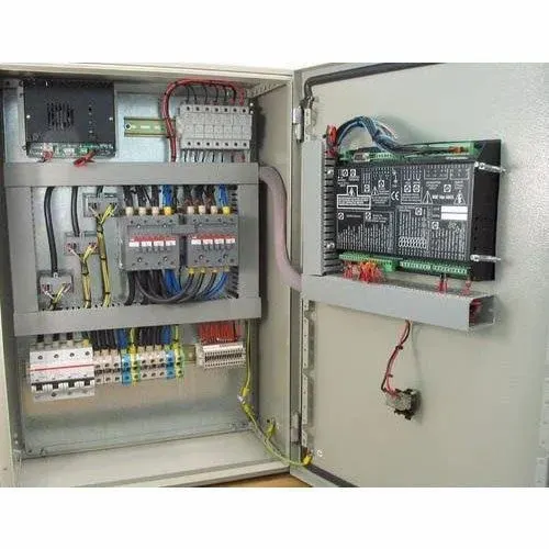
The Reference front view image has been attached below which is used for the modelling.
Also the dimensions and configurations of each and every components like busbars, circuit breakers and cables used in the system are provided below.
The Model has been created in stages as shown below:
1. Initialy, the ciruit breakers and busbars are created as per their length and cross section dimensions provided.
2. Then the connecting cables are created and connected to the circuit breakers.
3. Then, the Panel is designed as per the below mentioned dimensions along with the grilles to provide the airflow.
Panel dimensions: height 2000mm, width 1600 mm depth: 700mm with a thickness of 2mm.
Solid material: Carbon steel
Surface material: Acrylic paint
4. In the final stage, the Cabinet has been modelled with a dimension convenient for the natural convection analysis.
2. Meshing the model:
The General mesh settings used for meshing is shown below:
All the main components are added to an assembly and meshed separately along with slacks to control mesh bleeding with the below mentioned settings.
The Mesh has been displayed in the XY and YZ cutplane for a better visualisation.
The below attached image shows the mesh done on solid components which represents a moderate fineness.
The Quality of the mesh is also good and its listed below.
- Minimum skewness: 0.268
- Minimum volume: 2.6e-9
- Minimum face allignment: 0.446
3. Setting up the case:
3.1. Circuit breakers: For the circuit breakers, the total constant power supply value is provided as per the table. Also, they are updated with Cu-polished material.
3.2. Busbars and cables: For Busbars, the power supply is provided by activating joule's heating and the following parameters are updated through which the joule heating power is calculated. Similar procedure is done for all cables.
- Current
- Reference axis denoting the current flow
- Resistivity
- Joule heating coefficient
- Reference, low and high temperature
A Reference image of the settings done for busbar-"A" has been provided below.
3.3. Enclosure: The Thickness and materials are provided properly and radiation is assigned to all sides except top surface as requested in the sheet.
After the setup, required monitor points and post processing groups are created and the simulation settings are done as shown below.
3.4. Basic settings:
3.5. Discretisation schemes:
3.6. Under relaxation factors:
4. Solution description:
4.1. Residual plots:
From these plots, we can understand that the residuals starts rising after 300 iterations which indicates the temperature rise in air and starting of natural convection and gets converged at 600 iterations.
4.2. Monitor points
4.3. Object face contour
The Object face contour for temperature shows us the temperature distribution clearly. Here we can observe the temperature is low for the components near the lower grille as it provides the ambient air and temperature rises gradually when moved away from that. Also, at the back side of main circuit breaker, the temperature is high as five power cables are connected with a low relaxing space. The Maximum temperature attained by the components is 315.412 degC and lowest is 26.91 degC.
4.4. Particle traces
In the below attached figure, the flow trace and temperature contour is displayed for the co-relation of the results.
4.5. Temperature cutplot:
4.6. Report:
5. Conclusion:
In this project, we modelled a complete single-phase low voltage control panel as per provided dimensions and configurations and analysed it for the temperature rise in the system. The Maximum temperature attained is 315.404 degC at IG-1 cable due to its low relaxation space.