Thermal analysis of a Power board assembly using ANSYS Icepak
Objective of the project:
In this project, we are going to analyse an electronic enclosure using ANSYS Icepak platform. An Electrical enclosure is a cabinet for electrical or electronic equipment to mount switches, knobs and displays and to prevent electrical shock to equipment users and protect the contents from the environment. Electrical enclosures are usually made from rigid plastics, or metals such as steel, stainless steel, or aluminum. Steel cabinets may be painted or galvanized.
1. Geometry cleanup:
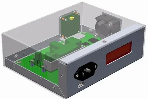
Initially, the Raw geometry of the total electronic containment has to be cleaned up and converted into Icepak understandable objects. An Image of the Raw geometry is provided below.
The Procedure and tools used in the Geometry cleanup are discussed sequentially below:
1.1 Removing unwanted fixtures: Initially, the fixtures of the cabinets are removed by using the split body command. Here, we need to create a plane that cuts the unwanted extrusions and the main object which will be used as a reference by split body command. An Example has been provided below.
Next, the Nuts and bolts has to be removed as its not going to take part in our CFD analysis. Here, we can use the selection tool, where we can select a sample object and using the selection option, we can identify all similar the similar instances, which makes it easier to remove all the bolts and nuts.
1.2. Simplification of geometry: The Next process is to convert all the objects into Icepak recognisable objects. Icepak can recognise only primitive shapes like Cuboid, cylinder and polygons, hence here the CAD geometry has been given certain level of simplification specifically based on their shapes and then converted into primitive objects.
Levels of Simplication:
- Level 0 - Bounding box
- Level 1 - Cuboid, Cylinder fit
- Level 2 - Polygon fit
- Level 3 - CAD object
Here, We are first converting the Interior components individually based on its required level of conversion.
When we take the interior components, there are basically, two major divisions: On board components and Under board components.
1.3.1. On board components simplification:
After simplifying basic cylindrical and rectangular objects, the model has some complex unconverted objects as shown in the image attached below.
These Objects are overlapping each other, hence a plane has to be created and splitted separtely using Split body command and then simplified using Icepak simplify option.
1.3.2. Underbody components simplification:
The Under body components mostly has small components which acts as a connectors between the over board components. These components can be easily simplified by provided a bounding box level of simplification.
1.3.3. Typical components:
In the Model, there are some typical components, where some are shown below.
Example-1: The Below show box cabinet has been first cleaned up for fillets and holes and then simplified to Level-2 polygon conversion.
Example-2: Here, the Pin connectors are directly simplified into a CAD object (Level-3) which basically converts the objects as a CSV object, which splits the body using multiple triangles.
Example-3: The Plug box is another typical example, which is converted into a high level refined CAD object (Refinement level controls the size of triangle elements).
1.3.4. Simplification of cabinets: After converting all the interior components, the Cabinet has been cleaned up and converted.
1. Initially, In the top cabinet, the Openings are created and grilles are provided in spaceclaim itself as shown below.
2. After providing the grilles, the unwanted holes and fillets are filled/removed and converted as cuboids (Level-1)
3. In the Bottom cabinet, the same procedure is followed and simplified.
1.3.5. Final simplified geometry: The Final simplified geometry is then feeded to Icepak for Meshing.
1.4. Interference checking in Icepak:
The Simplified model is imported into Icepak and its shown below. The Geometry is then checked for Intersections manually.
Example:
Here, we can see two cylindrical blocks intersecting with each other, which can be manually moved to a small distance to avoid overlapping.
After checking it manually, the macros can also be used to check for any interference between objects for confirmation.
After getting a confirmation through console as shown below, we can start the meshing process.
2. Meshing the model:
After importing the model, we have to resize the cabinet size as its a natural convection problem.
The Conformal mesh has been done in this study and the mesh parameters are described below.
Also, Multi level meshing is used in certain required objects to control the minimum volume and to improve the overall quality of the mesh.
Mesh along XY plane:
The Below mentioned pictures describes the mesh in XZ plane on All domain and Solid domain alone respectively.
Mesh normal to z plane
This Cut sectional mesh shows the effect of conformal mesh which creates the mesh bleeding throughout the domain.
Mesh Quality:
- Minimum Skewness: 0.091
- Minimum Cell volume: 0.1329
3. Setting up the case:
The Grilles and Heat sources are setup and in the model properly as per the configuration.
3.1. Basic parameters:
The Basic paramters like ambient temperature, guage pressure, default materials are choosed as shown below.
After that the Basic settings and advanced settings done are discussed below.
3.2. Basic settings:
3.3. Discretisation scheme:
3.4. Under relaxing parameters:
4. Solving and visualising the results:
4.1. Residual plot:
4.2. Monitor points for temperature:
The Solution has been ran upto 150 iterations and the convergence has been monitored through the monitor points and residual plot.
4.3. Temperature distribution on the components:
The Figures attached below explains the temperature distribution on the surface of internal components.
4.4. Cut-plane observation:
A Cut plane observation has been done below for understanding the velocity and temperature distribution on YZ plane in the heat sink.
4.5. Report data:
Through the report data, we can observe the Maximum temperature among the solid components of the assembly is 61.80 degC.
5. Conclusion:
The CAD object of an Electronic enclosure has been simplified into Icepak primitives, meshed with a conformal mesh and analysed properly for natural convection. The Maximum temperature in the domain is 61.8 degC which is within the safe limit, but it can be reduced even more by relocating the bracket which blocks the passage of air flow from the grilles.