Modelling and Analysis of a heat sink
Aim:
To analyse the temperature and velocity distribution of a finned heat sink contained within a cabinet of the dimensions specified in the problem statement.
Theory behind heat sinks:
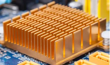
Heat sinks are extended surfaces to enhance the spreading of heat by conduction, and to increase the available surface area for convecting away the heat from the extended surfaces. They are passive heat transfer devices, meaning they aid in heat transfer without any external source of power.
Problem statement:
The cabinet contains an array of five high-power devices, a backing plate, ten fins, three fans, and a free opening, as shown in Figure. The fins and backing plate are constructed of extruded aluminum. Each fan has a total volume flow rate of 18 cfm and each source dissipates power at the rate of 33 W. According to the design objective, the base of the devices should not exceed 65°C when air sweeps the fins at an ambient temperature of 20°C
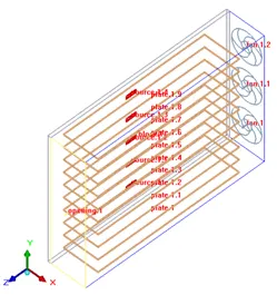
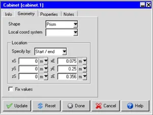
Cabinet Size: 75 mm X 250 mm X 356 mm
Backing plate: 6 mm thick
Opening: Cabinet is open on Z max
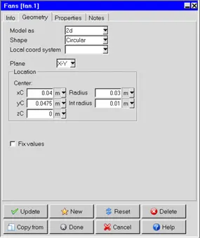
Fan 1: center is at Z min (40mm, 47.5 mm, 0mm) having an external radius of 30 mm and an internal radius of 10 mm. the fan has fixed volumetric flow 18 CFM
Fan 2: 77.5 mm from Fan1
Fan3: 77.5 mm from Fan 2
Source: Source 1 is located on the Backing plate at (0mm, 31.5 mm, 180.5 mm) having power dissipation 33W. there is total of 5 sources at 45mm distant apart.
Fins: total 10 fins of thickness 2.5 mm having width 69 mm in X dir and length 281 mm in Z dir and all fins are 25 mm apart (Fins are aluminum extruded)
Steps followed in the simulation setup
- Open Ansys Icepak and create a new project.
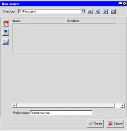
- Resize the cabinet with the dimensions specified in the problem statement
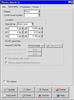
- Create the backing plate by clicking on the block option and then resize as shown in the next image
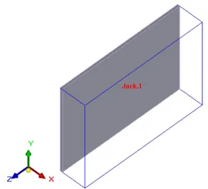
- The block is created as shown in the image below
- The next step would involve creation of the fins, fans and the openings for the simulation. Each step is explained as follows.
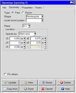
- Use the create openings icon to create the openings and resize as shown below
- Create the fan using the fans option available. In this simulation, all the three fans are identical and the only difference is the location in which they are mounted.
- Under the properties tab in the image above, specify the fan type as intake and the volumetric flow rate as 18 cfm. Once this fan is created, in the tree, right click the fan and select “copy”. Now set the number of copies to 2 and then specify the offset of 0.0775 m in the Y direction translation.
- The next step would be to create the sources. Click on the battery icon to create the source. Again, the sources are all identical, dissipating 33 W, each and the only difference is the location of them.
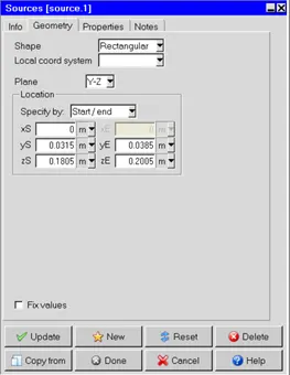
- Under the properties tab, enter 33 W as the total power. Now create this source, and use the copy option. Create 4 copies with translation and the offset of 0.045 mm. Now all the sources are created.
- Next step would be to create the fins, which are the ones that have not yet been created. Use the plates option to create the fins and resize and enter the dimensions as specified in the image below.
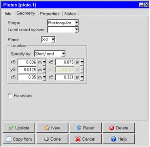
- Under the properties tab, change the option to make the plate “Conducting thick”, and use the thickness value to be 0.0025 m. Now use the copy option to create 9 other fins with the offset of 0.025 m. 10 fins will now be created and the entire setup for the simulation is now ready. It is shown below.
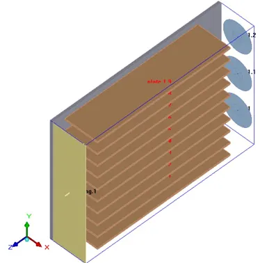
- As the model is ready, now the following steps are meshing and then followed by the simulation itself.
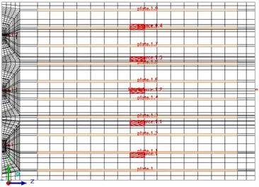
- Click the mesh controls icon and adjust the parameters as shown in the image below to obtain a coarse mesh. The mesh is visualized using the Y-Z cut plane, following which the decision to make a fine mesh will be taken.
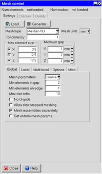
- Now click the generate mesh option. Once the mesh generation completes, under the display tab shown above, click on Display mesh, and select cut-plane in display attributes. Use the Y-Z plane and use the slider to correctly position where the mesh needs to be checked. The coarse mesh looks like the image below
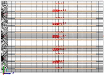
- In mesh parameters, change to normal mesh from coarse. This will generate a finer mesh. The finer mesh is shown in the image below and that will be used to carry out the simulation in order to get reasonably accurate results.
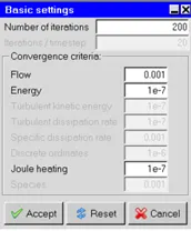
- Next involves the simulation setup. Under the solution settings, click the reset button so that the solver will find out the Reynolds and Peclet number. This can enable us to decide whether we need a turbulence model or not. In this case the Reynolds number is around 13000 and the Peclet number is 9000, hence the flow regime is turbulent. Change the number of iterations to 200.
- Now use the problem setup wizard to setup the problem. Ensure to use the following settings – solve for velocity, solve for temperature, use zero equation mixing length turbulence model after specifying that the flow regime is turbulent and ignore heat transfer due to radiation. This is simply because forced convection dominates and the effect of radiation is very small. Also, the nature of this analysis is steady state, so the variables do not vary with time.
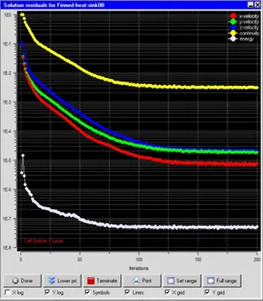
- Save the project and run the calculation. The residuals are shown as below
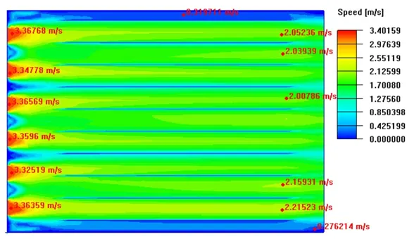
- The velocity contours are as below. Since the plot is a scalar contour, the variable has been named as speed.
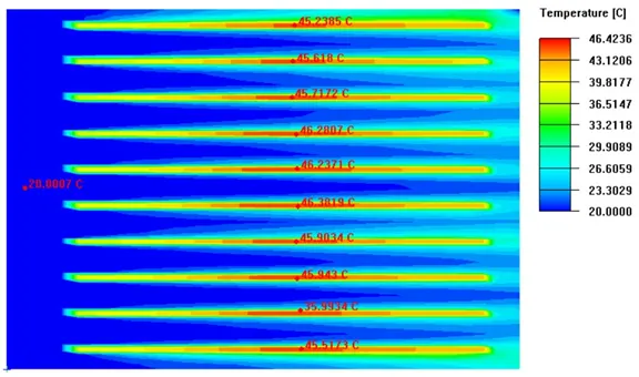
- The contours of temperature on the Y-Z plane are shown as below
- The temperatures of the sources are indicated in the image below, which contain the object face temperatures of the sources.
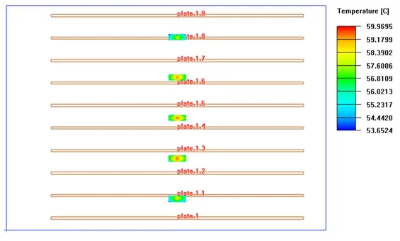
- Since the maximum temperature of the sources is only 59.96°C, the objective of having the temperatures below 65°C has been achieved.
Conclusion
Since the temperature of the sources are below 65°C, for the given airflow and the heat sink setup, we can consider that the high-power sources are thermally safe. However, if one fan or the other should fail to function, there may be bad thermal consequences for this system causing it to fail.