Meshing the Spare Wheel Floor Panel using Hypermesh
Aim:
1) Extracting the Mid-Surface and Meshing the given Back Wheel Floor Panel model using hypermesh according to the given quality criteria.
| S.No | Quality Criteria | Value |
| 1 | Aspect Ratio | 5 |
| 2 | Skewness | 45 |
| 3 | Warping | 15 |
| 4 | Taper | 0.5 |
| 5 | Min. Length | 2mm |
| 6 | Max. Length | 8mm |
| 7 | Min angle Quad | 45 |
| 8 | Max angle Quad | 135 |
| 9 | Min angle Tria | 20 |
| 10 | Max angle Tria | 120 |
| 11 | Tria % | 10 |
| 12 | Target Element Length | 5mm |
2) Assigning thickness to the meshed component and also creating property and material for that mid surfaced and meshed component.
Theory:
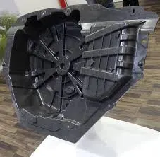
The model given to us is the Spare Wheel Floor Panel of an Automobile. This panel is manufactured using the stamping process were the raw material which is the steel or aluminium sheet is introduced into the die and hydraulic punch produces a punch so as to obtain the desired shape of the component.
Procedure:
1) We first import the model using the import model option.
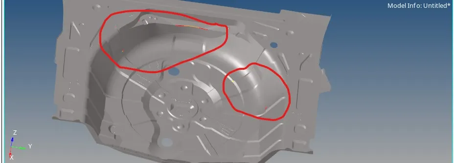
2) We see that, the model we have imported is the Spare Wheel Floor Panel of an automobile which has some geometrical issues that has to be cleared during the geometry cleanup as shown in the image given below.
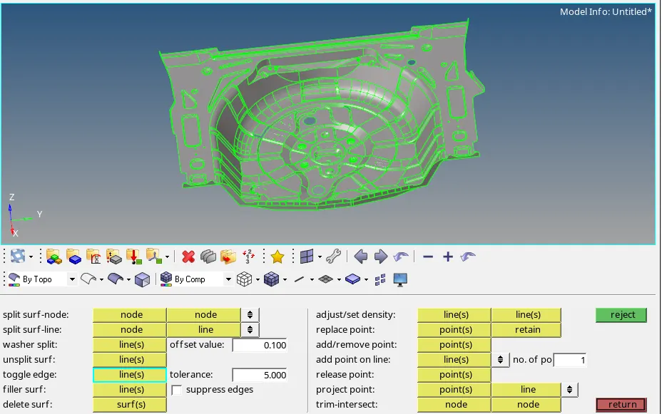
3) We do the geometry cleanup using the Quick Edit option which is present in the Geometry module as shown in the image given below.
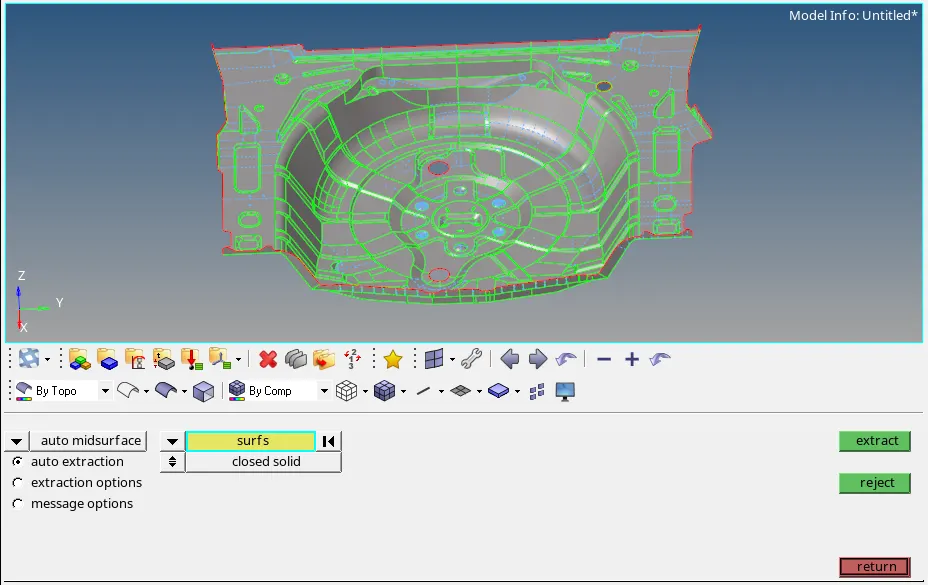
4) We then, extract the mid-surface for the component using the auto-midsurface (skin offset) option present in the Geometry module as shown in the image given below.
5) We then, proceed to mesh the mid-surfaced component, but before that we need to input all the quality criteria as mentioned in the aim. We go to the preferences tab and click on criteria file settings option and input all the quality parameters required to be passed while meshing the mid-surfaced component as shown in the image given below.
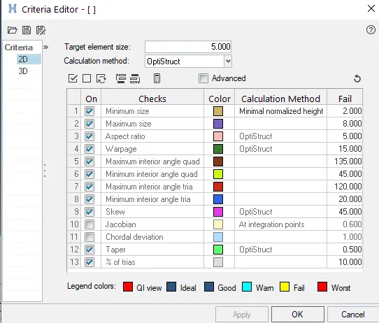
6) After inputting all the quality criteria mentioned in the aim, we toggle off the lines which may cause quality failures on meshing the component using the toggle option under quick edit tab of the Geometry module. We then, start meshing the component region by region using the Automesh option with target element length as 5mm and element type as mixed as shown in the image given below.

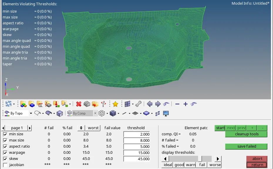
7) After meshing the component, we see that the component is failure for quality in some regions for that, we use the QI tools in the Quality index tab of the 2D module and we use other tools like Smooth, Rebuild mesh and elem cleanup options present in the 2D module. The options are shown in the images given below.




8) After we clear all the quality issues using the above mentioned options we get a good smooth mesh finish without any quality issues as shown in the image given below.
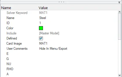
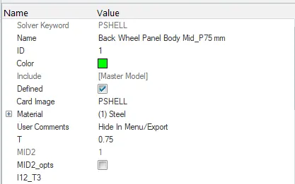
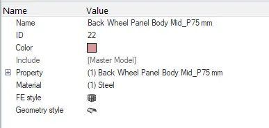
9) After that, finally we assign the thickness to the component by creating the property and material for the mid-surfaced and meshed component by right clicking on the Browser tree. The property and material created are shown in the images given below.
Conclusion:
1) We have done the geometry cleanup for the Spare Wheel Floor Panel of an Automobile.
2) We have extracted the mid-surface for the component using the auto-midsurface option.
3) We have meshed the component according to given quality parameters in the aim.
4) We have removed all the quality failures using the QI tools, Smooth, Rebuild mesh and elem cleanup options and we have obtained a good mesh flow over the component.
5) We have also assigned thickness to the component by creating property and material for the component.
6) Finally the thickness assigned is visualized using the 2D detailed element representation option under the Visualization toolbar.