Meshing of Car Backdoor Geometry
AIM
For this challenge, you will have to mesh the backdoor geometry of a car that is provided below. Provided below is the quality parameters that you have to follow.
Target Element size - 5mm
| S.N | Quality Criteria | Value |
| 1 | Aspect Ratio | 5 |
| 2 | Skewness | 45 |
| 3 | Warping | 15 |
| 4 | Taper | 0.5 |
| 5 | Min. Length | 3mm |
| 6 | Max. Length | 7mm |
| 7 | Min angle Quad | 45 |
| 8 | Max angle Quad | 135 |
| 9 | Min angle Tria | 30 |
| 10 | Max angle Tria | 110 |
| 10 | Tria % | 15 |
Note: Attach the hypermesh model files (.hm) with the challenge
Click here to download the Backdoor Model
Introduction
Backdoor of a car is aso called tailgate. A car backdoor consist of inner pannel, 2-3 outer pannel & reinforcements. Car backdoor is mainly made of steel or aluminium based on the budget of a car. The inner pannel consist of hinge reinforcement, gasstay reinforcement, latch and striker reinforcement & wiper motor housing. Using aluminium improves the strength of the parts as well as reduce the weight of the backdoor& also we can vary thickness in the aluminium parts due to which we can avoid the reinforcement. The only drawback is the cost of aluminium. For steel parts we cannot vary thickness of the parts and theses parts are stamped & more number of parts are added which in turn increse the weight of the backdoor.
Part_1
Geometry Import
Geometry of backdoor has been imported in hypermesh window.Geometry consists of three components.
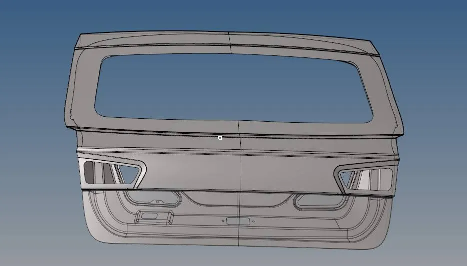
After that topoloy visualization has been done , to check for any error which needed to be remove the geometry.
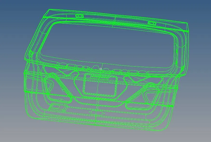
Geometry Cleanup
As there are some open edges , we need to perform geoemtrical clean up , before midsurfacing and meshing , opertiws if will cause problem during analysis.
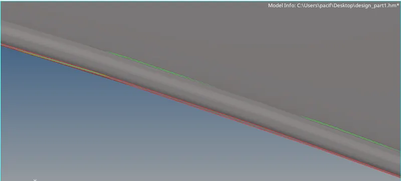
To solve this problem we have used , equivalence surface edges option and replace tool to fixed the problem.

Midsurface
Midsurface tool that allows you to find and extract surfaces from single thickness thin solid geometry.
The original geometry that we selected to extract the midsurface from remains unchanged, and the new geometry that represents the midsurface is placed in a component called Middle Surface, or in the current component, depending on your selection.

We have selected autosurafce option with skin offset.
Extracted midsurface obtained is shown below:
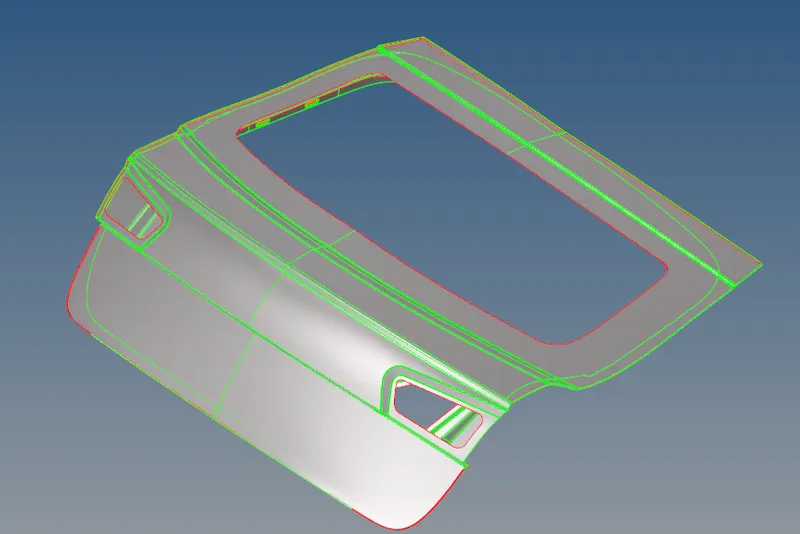
Extracted midsurface is arrage in three dufferent components.
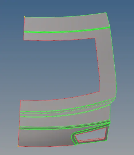
Surace split
As the given surface is symmetry is nature. We can split the surface in two different parts and performs meshign on half parts and refrent that on other side, that will save the computation time.

split surface obtain is shown below:
Meshing
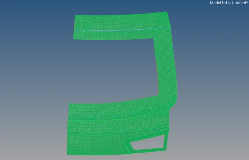
The basic idea of FEA is to make calculations at only limited (Finite) number of points and then interpolate the results for the entire domain(surface or volume). Any continuous object has infinite degrees of freedom and it’s just not possible to solve the problem in this format. Finite Element Method reduces the degrees of freedom from infinite to finite with the help of discretization or meshing (nodes and elements).

The automesh panel creates shell mesh on existing surfaces
• Allows rapid generation of mesh
• Most parts from CAD software come in as surfaces
• Automeshing allows all surfaces of a part to be meshed at the same time
• Mesh on properly connected geometry assures proper connectivity of mesh
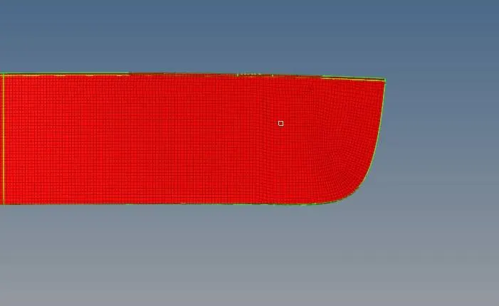
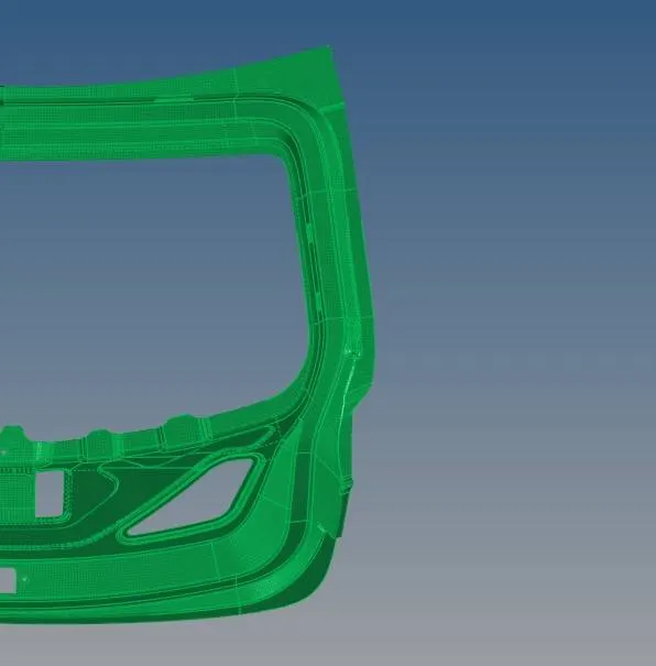
Mesh generated by the different components is shown below.
Desnsity_variation
After meshing we have performed the density adjustment of the mesh , so that we can get as much structured elements as possible to get better result.

Remeshing
Remeshing is need to be done to remove the rotating tria elemnts of the components surface.

the components selected are shown below:
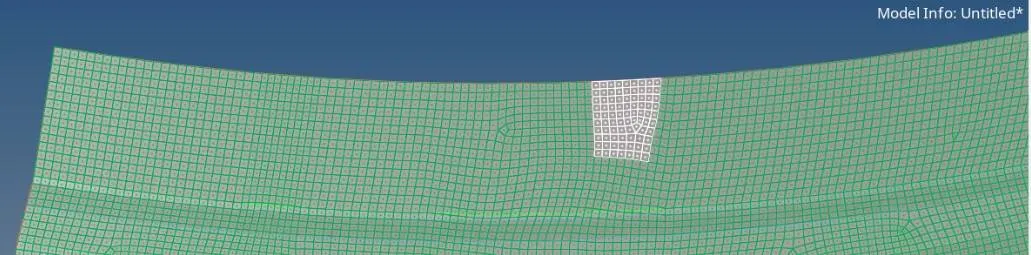
as we can see there are rotating elements is the selected elements,that rotated elements is meshed to remove the elements.
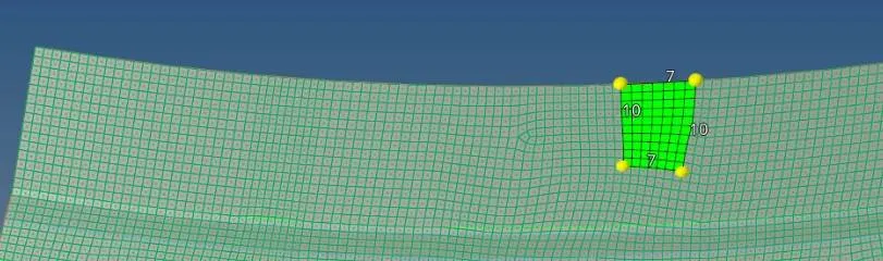
Meshing cleanup
After meshing ,next step is mesh cleanup to meet our mesh criteria requirement.
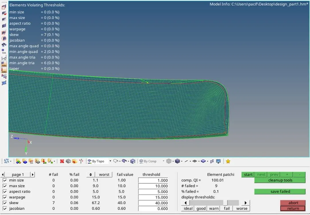
It can be see that there are 9 elemnts which are failed to meet the mesh requirement. It can be cleaned by using cleanup tools.

Reflect
After meshing ,next step is to reflect the elements to get the full elements in the z direction as per the components direction.

------------------------------------------------------------------------------------------------------------------------------------
Full components obtained is shown below:
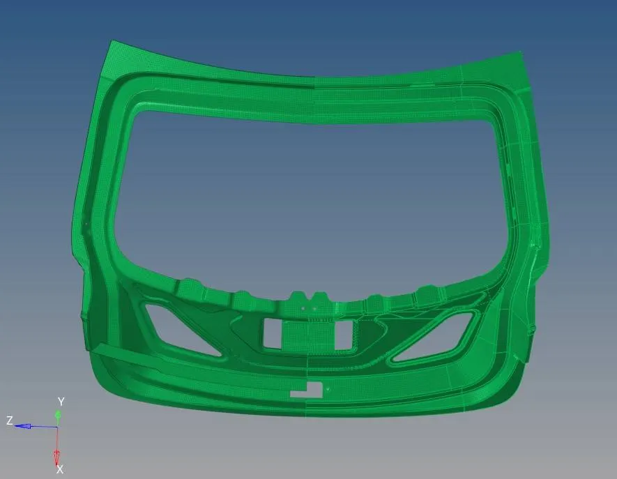
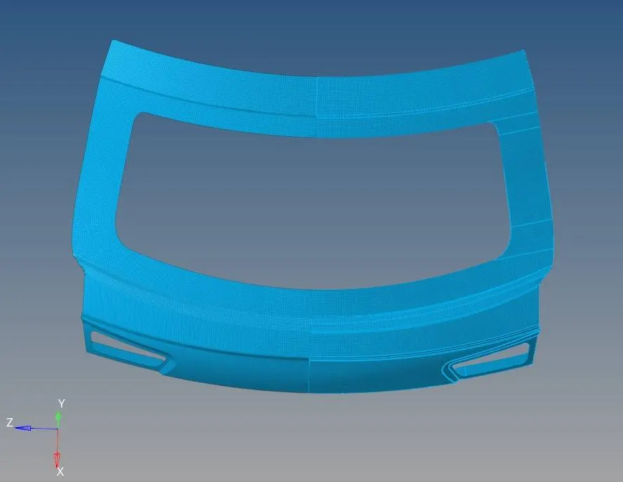
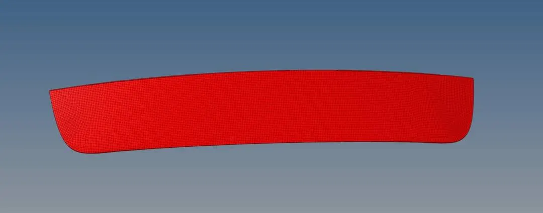
Full preview is shown below:
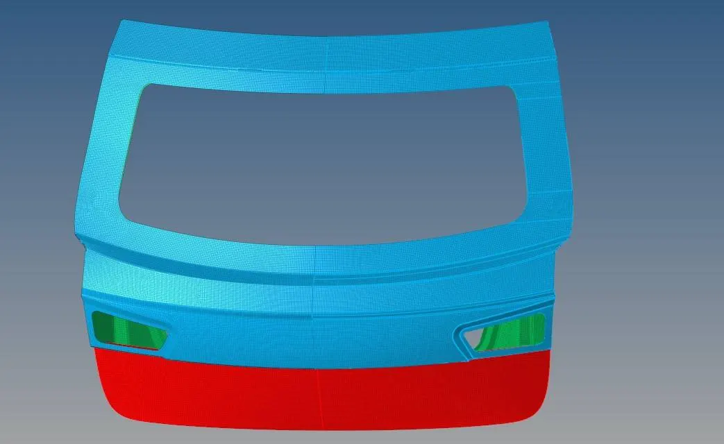
Conclusion
- Given challenge has been successfully performed, for the given mesh criteria.
- Mesh cleanup has been successfully performed of the car backdoor model.