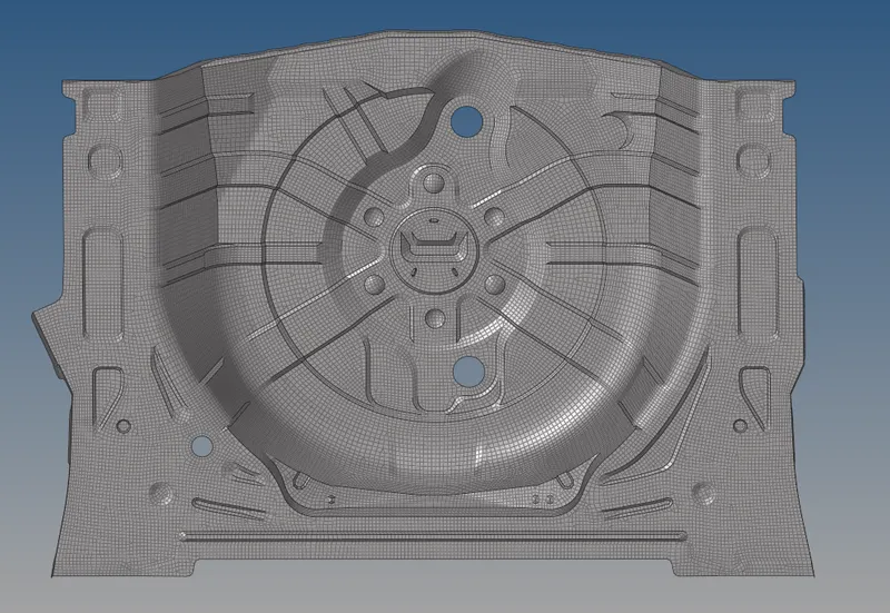
Meshing Wheel Floor Panel using HyperMesh
Objective:
- To clean up the geometry.
- Extract mid-surface of the model.
- To mesh the model.
Theory:
All real life objects are continuous.Means there is no physical gap between ant two consecutive particles.As per material science,any object made of small particles,particles of molecules,molecules of atoms and so on and they are bonded together by force of attraction.Solving a real life problem with continuous material approach is difficult and basic of all numerical method is to simplify the problem by descritizing it.In simple words, nodes work like atoms and gaps are filled by an entity called element.Calculations are made at nodes and results are interpolated for elements.
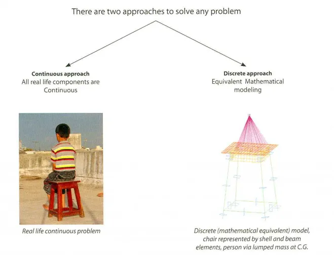
Different types of numerical methods are,
- Finite element method.
- Boundary element method.
- Finite volume method.
- Finite difference method.
Types of elements in Meshing:
- 1D element:
Used for geometries having one of the dimensions that is very large in comparision to the other two.
Example:Long shaft,rod,beam,column,spot welding,bolted joints,springs etc.
- 2D element:
Used when the two dimensions are very large compared to the other one.2D meshing is carried out on a mid surface of the part.2D elements are planar.Thickness is assigned as additional data.Mathematically,the element thickness specified by the user is asiigned half on the element top and half on the bottom side.So,it is necessary to extract the mid surface and then mesh on the mid surface.
Example:Thin shell plate,plastics etc.,
- 3D element:
Used when all the dimensions are comparable.element types like tetra and hexa are used.
Example: Engine block,crankshaft etc.,
- Other:point element,concentrated mass(conMi),damper or damping co-efficient.etc.,
Advantages of FEA:
- High visualization of results.
- Design cycle time decreases.
- Very less number of prototypes.
- Testing time and iterations wil be less.
Abstract:
Back panel of a wheel consists high number of beads and holes and feautures that will cause complications while meshing.So we mesh these components with little defeauturing with the below mentioned quality criteria.
Target Element Length = 5mm
| S.N | Quality Criteria | Value |
| 1 | Aspect Ratio | 5 |
| 2 | Skewness | 45 |
| 3 | Warping | 15 |
| 4 | Taper | 0.5 |
| 5 | Min. Length | 2mm |
| 6 | Max. Length | 8mm |
| 7 | Min angle Quad | 45 |
| 8 | Max angle Quad | 135 |
| 9 | Min angle Tria | 20 |
| 10 | Max angle Tria | 120 |
| 10 | Tria % | 10 |
Procedure:
1.We import the model to HyperMesh.
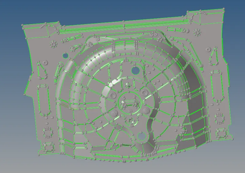
2.To check the model for open surfaces and attached surfaces, we check the model manually and found no issues.
3.As the model is having uniform thickness,which is found to be 0.75 mm, we go for auto mid-surfacing.Then we assign the thickness for it.
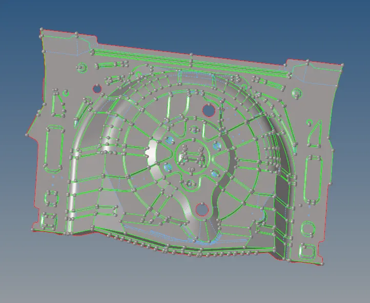
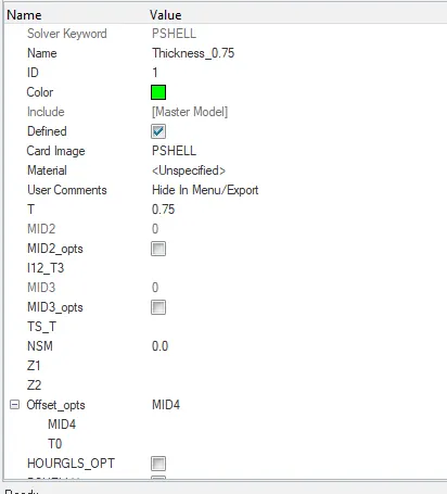
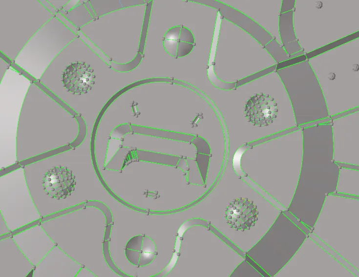
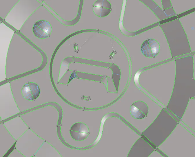
4.Construction lines that fall under minimum element length are to be removed and some features are removed as shown below.
| Before | After |
 |
 |
 |
 |
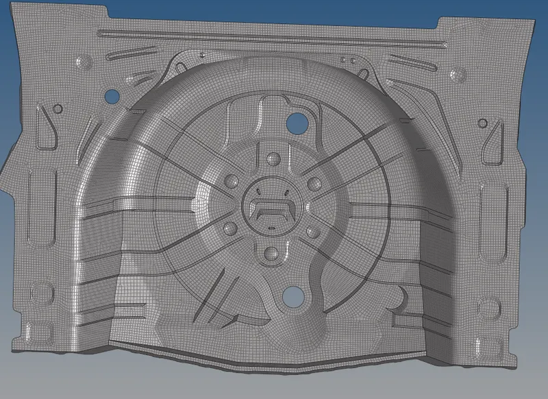
5.Now meshing is done by 'Automesh' using the above mentioned criteria and quality errors are rectified.
6.We need to check for connectivity of the mesh.So we go to tools>find edge>select component>find edges.Mesh is well connected for the model.
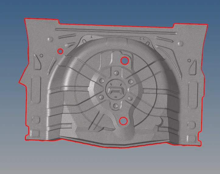
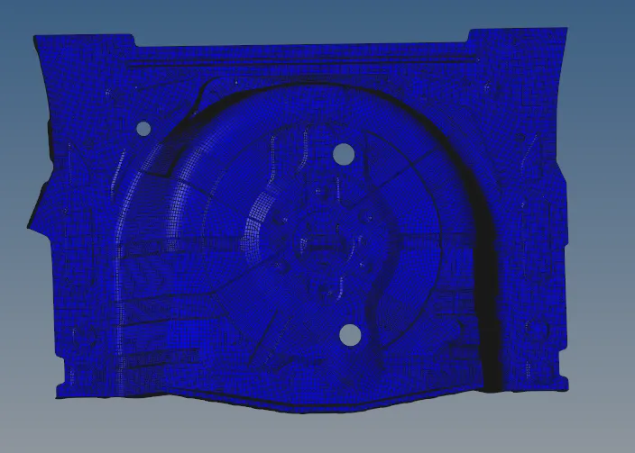
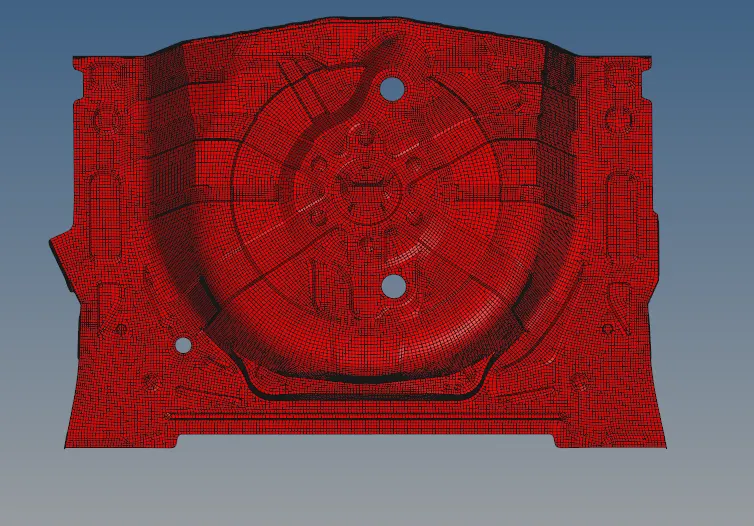
7.We need to find the vector direction or normal direction for the elements.So we check Tools> normal> display for elements.
 |
 |
RESULTS:
We get a quality mesh as shown below.