Meshing an automobile hood model using Hypermesh
Aim:
1) To check the geometry for the given model.
2) To extract all the mid surfaces of the given component.
3) To mesh all components in the model using the following quality criteria and finally giving thickness to the component.
| S.No | Quality Criteria | Value |
| 1 | Aspect Ratio | 5 |
| 2 | Skewness | 45 |
| 3 | Warping | 15 |
| 4 | Taper | 0.5 |
| 5 | Min. Length | 2 mm |
| 6 | Max. Length | 8 mm |
| 7 | Min angle Quad | 45 |
| 8 | Max angle Quad | 135 |
| 9 | Min angle Tria | 20 |
| 10 | Max angle Tria | 120 |
| 11 | Tria % | 10 |
| 12 | Target Element Length | 5 mm |
Theory:
The model we use in this challenge is a car hood model. The hood is the hinged cover over the engine of motor vehicles that allows access to the engine compartment, or trunk for maintenance and repair.

A Hood Consists of four parts namely:
1) Outer Extract or the outer cover
2) Inner Extract or the inner cover with the perforations for locking the inside parts.
3) Latch Reinforcement, which is attached to the inner extract for locking the hood.
4) Hinge Reinforcements, which is used to make a hood stand on its own at an angle while doing repair or maintainance work.
Procedure:
1. Importing the model and geometry cleanup:
1) We import the hood model using the import geometry option. The full hood model shown in the image given below.
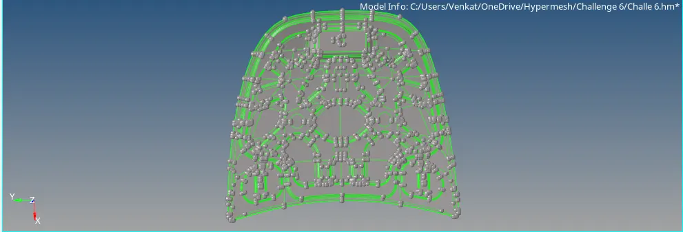
2) We then, see that the geometry is good and free of any errors so we proceed to take the mid-surface part by part.
2. Mid surfacing:
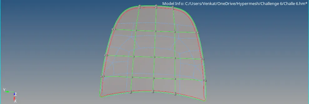
3) We proceed to take the mid-surface for each component. First, we take mid-surface for the outer extract by using the mid-surface option and we rearrange the construction lines using the split surface node option in quick edit toolbar as shown in the image given below.
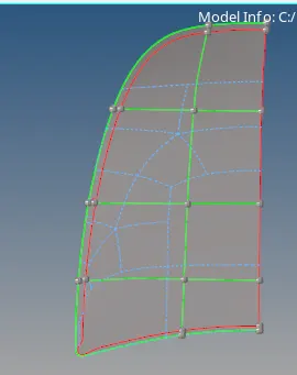
4) We then, delete symmterical surfaces using the delete option so that, after meshing one half we can reflect the other half as shown in the image given below.
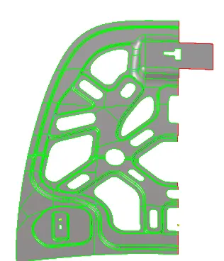
4) Similarly, we take the mid-surface for other components Inner Extract, Latch and Hinges as shown in the images given below.
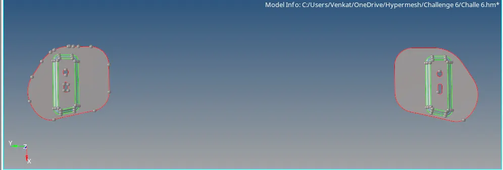
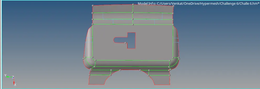
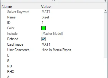
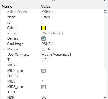
5) We then, use the create option by right clicking on the model browser and create properties & material for the mid-surfaced components and also assign thickness to the components as shown images given below.
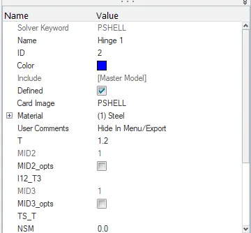
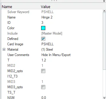
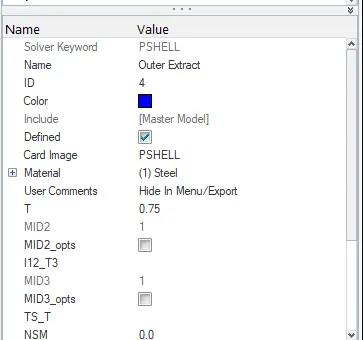
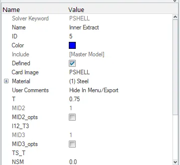
6) We then, alter the construction lines before meshing using the toggle option in the quick edit toolbar and then we proceed for meshing the components one by one.
3. Meshing:
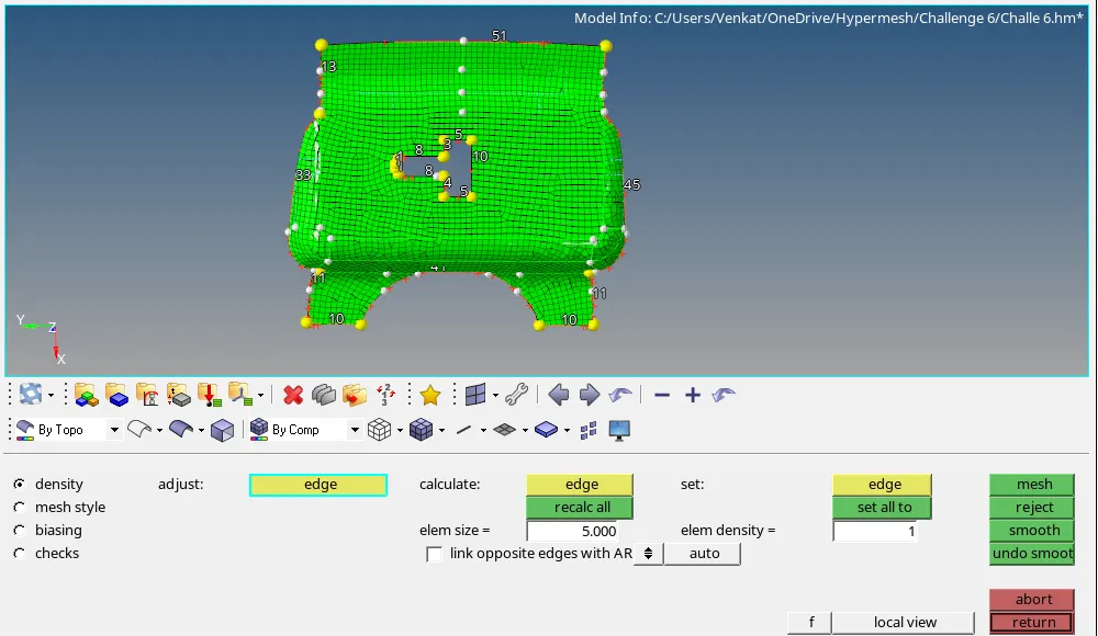
1) We first take the Latch and perform mesh over the whole component region by region to obtain a good mesh. We mesh the component with 5 mm as target element length as shown in the aim. The meshed latch is shown in the image given below.
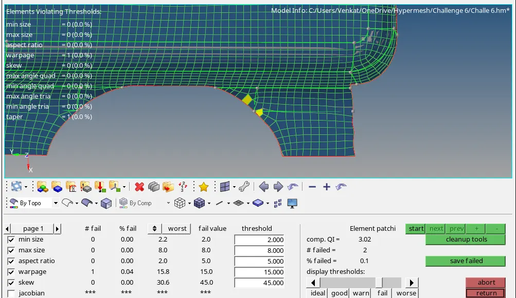
2) We use the quality index under the 2D module and we check for any quality issues. We find that there are quality issues in some regions for that, we the QI tools like Element optimize, swap edge, drag tria etc. to get a proper mesh flow as shown in the image given below.
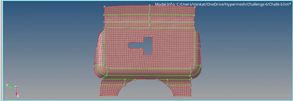
3) After that, we use smooth option under the 2D module to smooth the mesh such we obtain a better mesh flow as shown in the image given below.
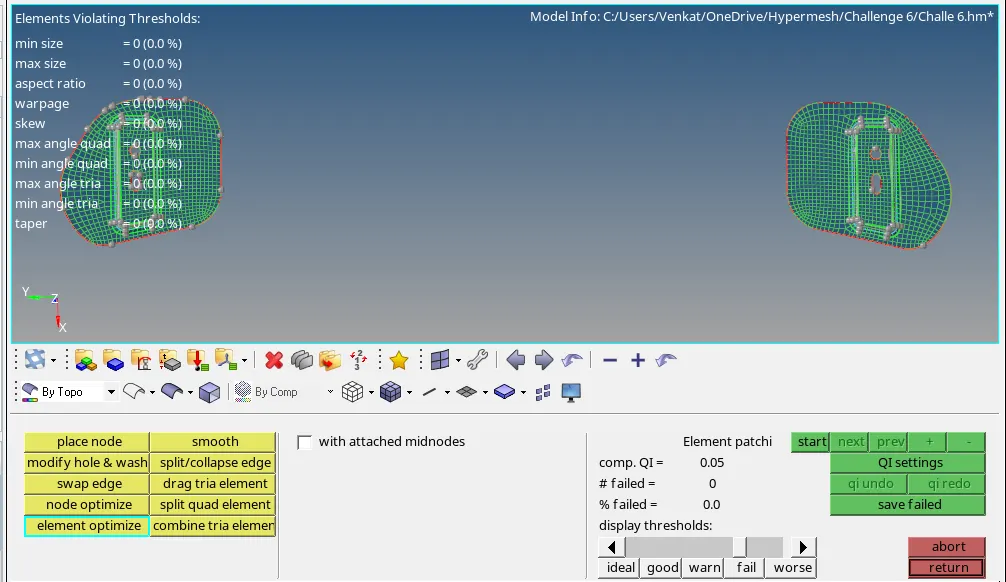
4) We follow the similar process for the Hinges and perform the mesh and clean up the errors using the quality index and finally, perform smooth option over the whole component. We finally get the good mesh over the hinges which is free of quality errors as shown in the image given below.
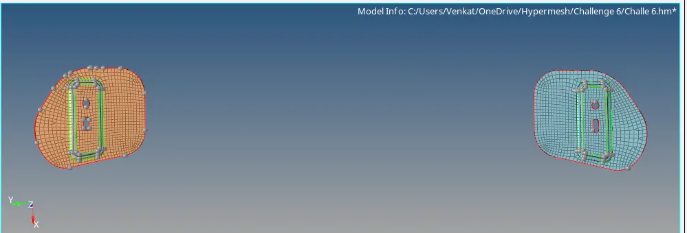
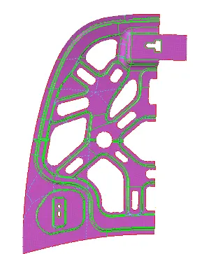
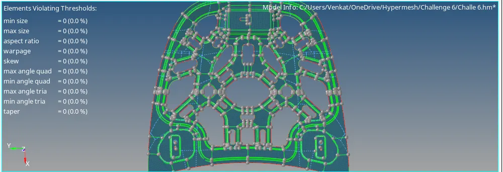
5) The inner extract has several parts and it's difficult to have fine mesh on the surface, to get it properly done it is divide into the smaller parts. The Surfaces are divided into smaller rectangular surfaces to have proper mesh wherever possible but while connecting with the different surfaces it getting free edges. The free edges are removed with equivalence and manually replacing the node. At the circle adding the washer split of 5mm to capture normal quad elements. While correcting errors at the curve surface, probably meshing at such surface getting warpage which fixed by splitting the surface and moving the trias at some distance. Opposite trias are not removed which are at different surfaces to avoid alignment of elements and also it is acceptable at big parts. While fixing errors on given quality criteria always maintain the elements align to the feature line. All errors are fixed and achieved the fine mesh with maintaining the trias management and proper quads. The image given below shows in the component is free of quality errors.
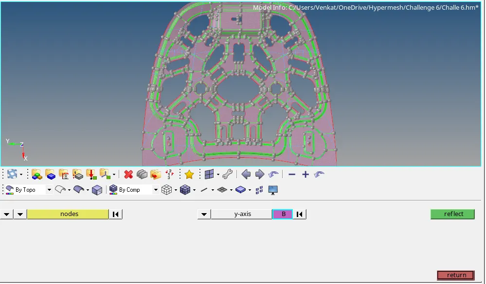
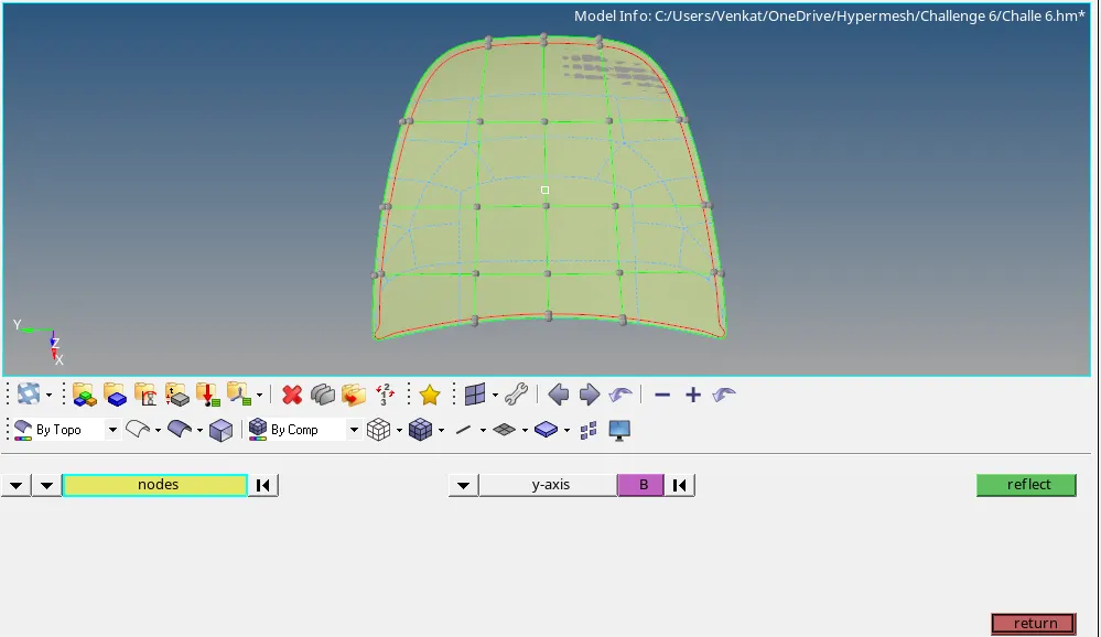
6) We use the reflect option to reflect the symmetric surface and obtain surface free of any quality errors as shown in the images given below.
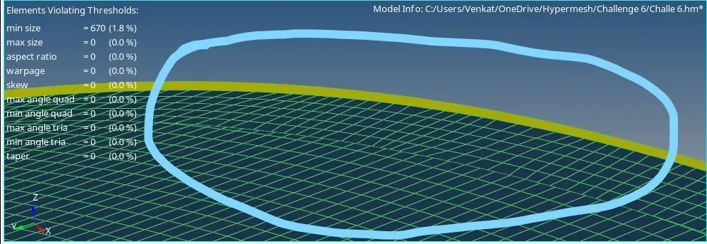
7) The similar process is carried out for the outer extract, all the Quality issues are cleared. But at the hemming part it difficult to capture mesh properly it showed the error and the element was below minimum size 2mm as shown in the image given below.
8) We then, use the reflect option to reflect the symmetric surface as shown in the image given below.
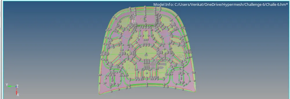
9) We finally, get a good mesh over all the components as shown in the image given below.
Conclusion:
1) The given hood model was checked for geometry errors and cleared.
2) The mid-surface was generated for all the components in the Hood.
3) The properties and material were assigned to all the components in the model browser.
3) The Components were meshed seperately using the quality criteria given in the aim, the quality issues were cleared using the quality index option and symmetrical surfaces with the mesh for inner and outer extracts were bought back using the reflect option.