Meshing an automobile backdoor model using Hypermesh
Aim:
1) To perform geometry cleanup for the given backdoor model.
2) To perform manual mid-surfacing for all the components in the backdoor model.
3) To mesh the backdoor geometry of a car according to the quality parameters given below.
| S.No | Quality Criteria | Value |
| 1 | Aspect Ratio | 5 |
| 2 | Skewness | 45 |
| 3 | Warping | 15 |
| 4 | Taper | 0.5 |
| 5 | Min. Length | 3.5mm |
| 6 | Max. Length | 7mm |
| 7 | Min angle Quad | 45 |
| 8 | Max angle Quad | 135 |
| 9 | Min angle Tria | 30 |
| 10 | Max angle Tria | 110 |
| 11 | Tria % | 15 |
| 12 | Target Element Length | 5mm |
Theory:
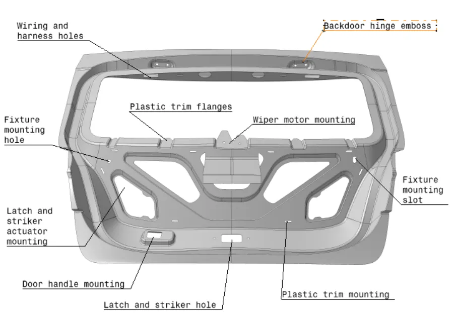
The model given to us is the Backdoor BIW model of a car.
Procedure:
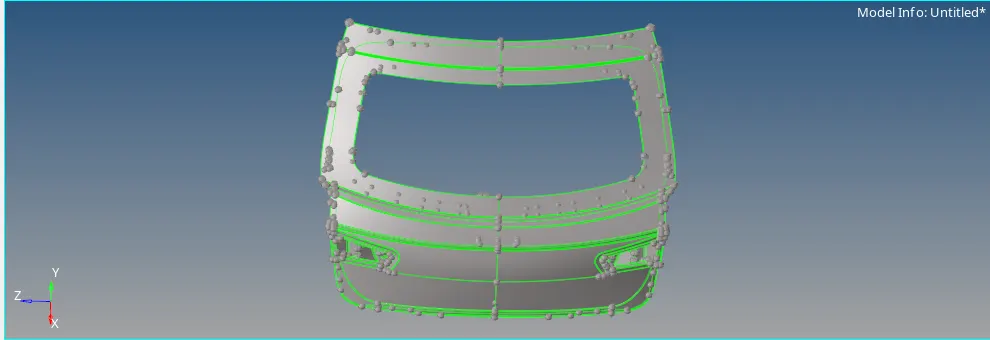
1) We first use the import option to import the CAD model. The imported CAD model is shown in the image given below.
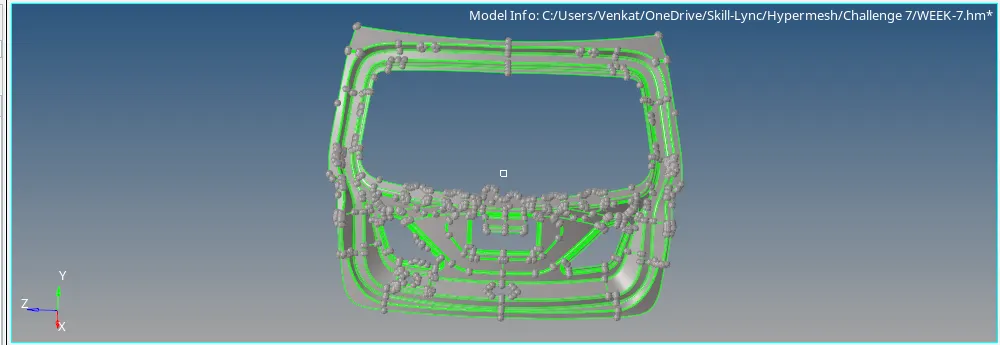
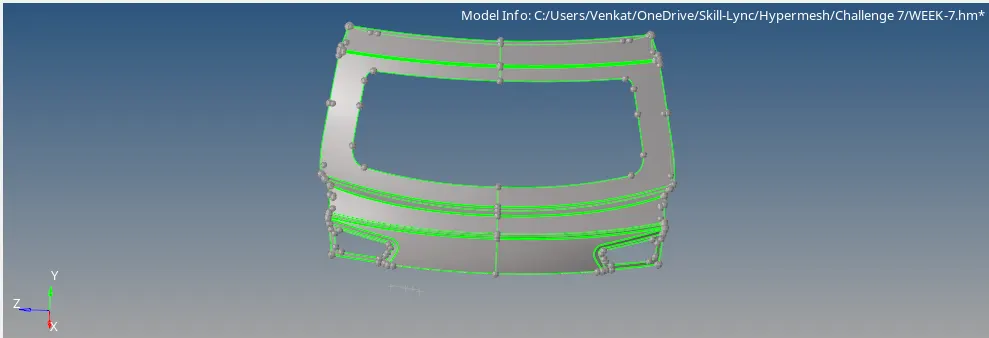
2) There are three components namely Upper body, Lower body and Inner body as shown in the images given below.
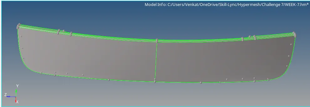
3) We perform geometry cleanup for the components using the quick edit option in the geometry toolbar for the lower body only because the upper and inner body's have clean geometry. The quick edit option is shown in the image given below.

4) We then, extract their mid-surfaces using offset option in Geometry model using the Surface edit. The offset distance is half of the thickness of the component. The offset option is shown in the image given below.

Outer Body:
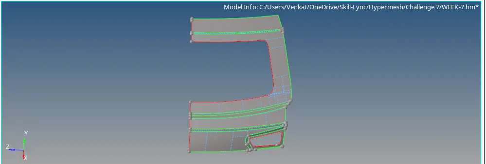
For the outer body, the model is symmetric therefore, we delete one side of the model and work on the other side of it. We work on further cleaning up of the mid-surface component part by part. Defeaturing is done to remove the details like surface fillets, edge fillets, pinholes etc to make geometry simpler by using the defeature command. The outer body half and defeature option are shown in the images given below.

Inner Body:
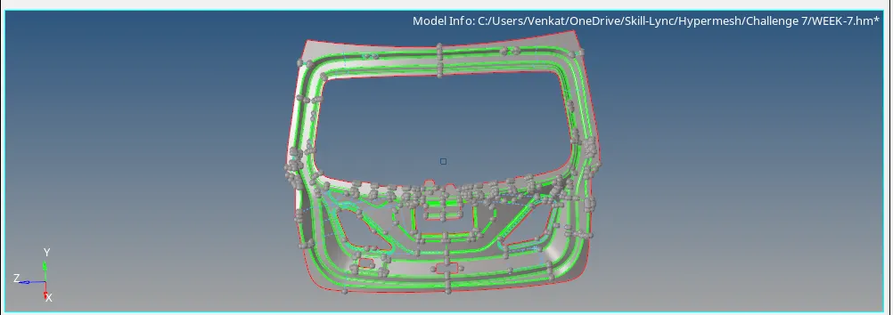
For the Inner body, the surface is not symmetric. We work on further cleaning up of the mid-surface component part by part. Defeaturing is done to remove the details like surface fillets, edge fillets, pinholes etc to make geometry simpler by using the defeature command. The inner body is shown in the image given below.
Lower Body:
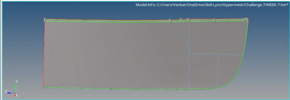
For the Lower Body also, the model is symmetric therefore, we delete one side of the model and work on the other side of it. We work on further cleaning up of the mid-surface component part by part. Defeaturing is done to remove the details like surface fillets, edge fillets, pinholes etc to make geometry simpler by using the defeature command. The lower body is shown in the image given below.
5) Now, we define the property and material for each of the mid-surfaced components by right clicking on the model browser window. The properties and material defined are shown in the images given below.
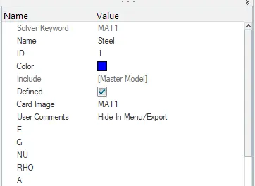
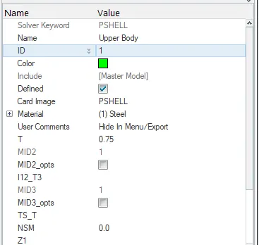
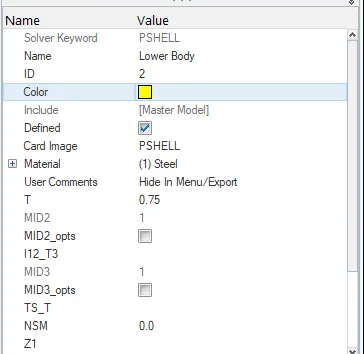
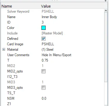
6) Now, we set the quality criteria for the mesh to be followed by using the criteria file settings in the preferences option. The criteria file settings is shown in the image given below.
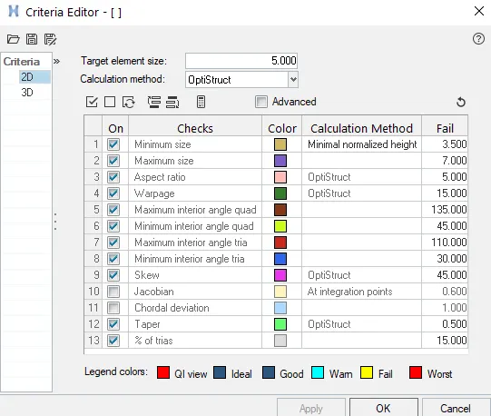
7) We then, mesh each component according to the specified quality criteria in the aim using the automesh option in the 2D module as shown in the image given below.

Outer Body:
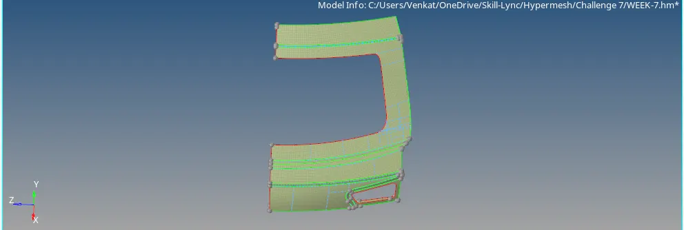
We mesh the outer body half region by region and we then clear all the quality errors caused using the QI settings in the quality index option. We get a good mesh over the outer body half. The images given below shows the QI settings and meshed outer body half.

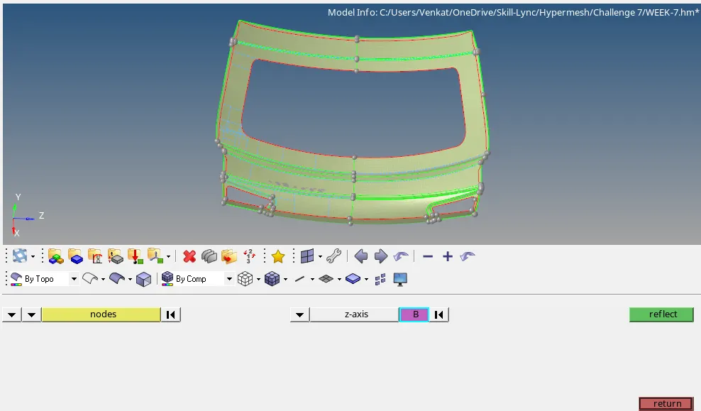
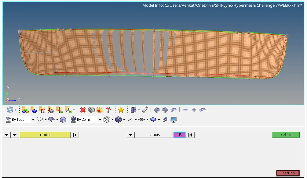
We then reflect the mesh and surface on the other side using the reflect option in the tools module. The reflect option is shown in the image given below.
Inner Body:
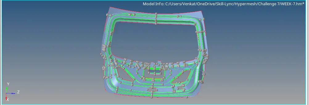
We mesh the inner body region by region and we then clear all the quality errors caused using the QI settings in the quality index option. We get a good mesh over the inner body. The image given below shows the meshed inner body.
Lower Body:
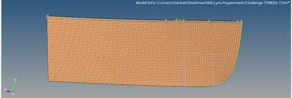
We also mesh the lower body half region by region and we then clear all the quality errors caused using the QI settings in the quality index option. We get a good mesh over the lower body half. The image given below shows the meshed lower body half.
We then reflect the mesh and surface on the other side using the reflect option in the tools module. The reflect option is shown in the image given below.
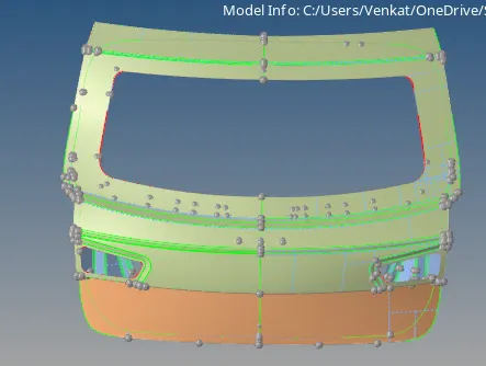
8) We finally, get the good mesh flow over the all components and in the hemming bend of the upper body & lower body the elements are failing for min length since the element length is less at the bend region. The fully meshed components are shown in the image given below.
Conclusion:
1) We have imported the CAD model i.e. the Backdoor Model.
2) We have done the geometry cleanup for all the components.
3) We have done manual mid-surfacing using the offset option for all the components and we cleaned up the mid surfaced components and then, we have deleted one half of the symmetric components like upper body and lower body.
4) We have inputted the quality criteria in the criteria file settings for meshing the component. We have obtained the good mesh flow and we reflect the mesh and surface for symmetric components using the reflect option.
5) Due minimal length in the hemming bend region of upper body and lower body, we get quality issues which are ignored.
6) We have meshed all the components and we assign the properties and material for all the components.