MBD Simulation on IC Engine Valve Train
AIM:
- To generate the 3D model of the Cam,Push rod,Rocker arm,Valve stem,valve.
- To simulate assembly as per given conditions
Theory:
A valvetrain or valve train is a system that controls operation of the intake and exhaust valves in an internal combustion engine.The intake valves control the flow of air/fuel mixture (or air alone for direct-injected engines) into the combustion chamber, while the exhaust valves control the flow of spent exhaust gasses out of the combusion chamber once combustion is completed.
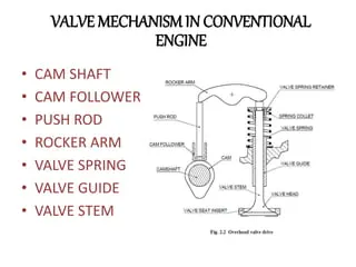
The valvetrain consists of all the components responsible for transferring the rotational movement of the camshaft into the opening and closing of the intake and exhaust valves. Typical components are listed below in order from the crankshaft to the valves.
Camshaft
The timing and lift profile of the valve opening events are controlled by the camshaft, through use of a carefully shaped lobe on a rotating shaft. The camshaft is driven by the crankshaft and— in the case of a four-stroke engine— rotates at half the speed of the crankshaft.
Motion is transferred from the crankshaft to the camshaft most commonly by a rubber timing belt, a metallic timing chain or a set of gears.
Pushrod
Pushrods are long, slender metal rods that are used in overhead valve engines to transfer motion from the camshaft (located in the engine block) to the valves (located in the cylinder head). The bottom end of a pushrod is fitted with a lifter, upon which the camshaft makes contact. The camshaft lobe moves the lifter upwards, which moves the pushrod. The top end of the lifter pushes on the rocker arm, which opens the valve.
Rocker arm / bucket tappet
Depending on the design used, the valves are actuated by a rocker arm, finger or bucket tappet. Overhead camshaft engines use fingers or bucket tappets, upon which the cam lobes contact. Overhead valve engines use rocker arms, which are actuated by a pushrod and pivot on a shaft or individual ball studs in order to actuate the valves.
Valves
Most modern engines use poppet valves type. These are typically opened by the camshaft lobe or rocker arm, and closed by a coiled spring called a valve spring.
CAM DESIGN:
Case 1 :
Cam lift = 3.5 mm
Distance between the centres = L
Cam lift = (L-R1)+R2
3.5 = (L-17.5)+10
3.5 = L-7.5
L = 11 mm
Cam 1 data :
Diameter of lower circle (D1) = 35mm.
Diameter of upper circle (D2) = 20mm.
Distance between the centres (L) = 11mm
Case 2 :
Cam lift = 6 mm
Distance between the centres = L
Cam lift = (L-R1)+R2
6 = (L-17.5)+10
6 = L-7.5
L = 13.5 mm
Cam 2 data :
Diameter of lower circle (D1) = 35mm.
Diameter of upper circle (D2) = 20mm.
Distance between the centres (L) = 13.5mm
Procedure:
- Design 2 cams with different heights as per calculation as shown below.
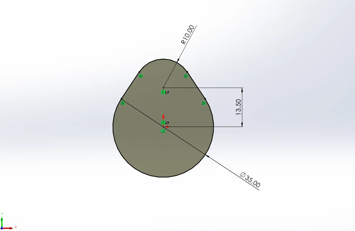
- Similarly design 3d models of push rod, rocker arm etc.
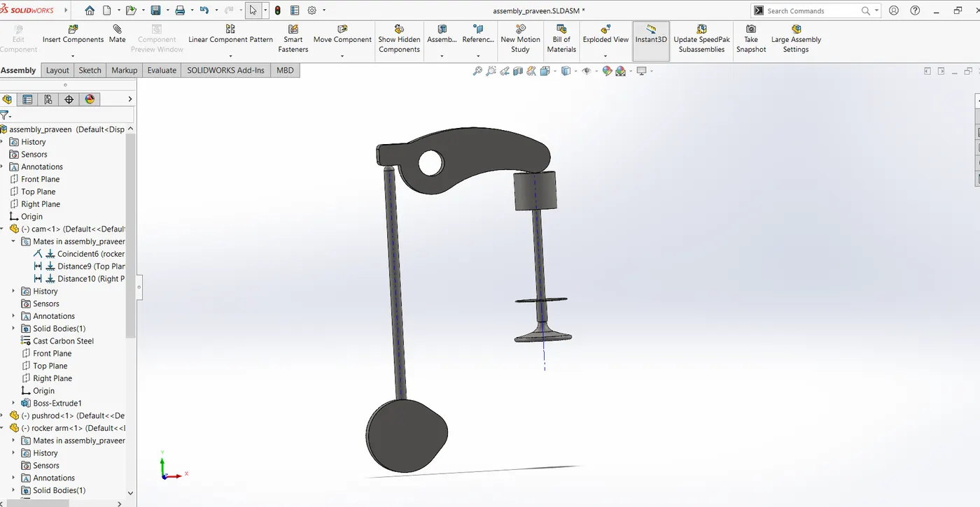
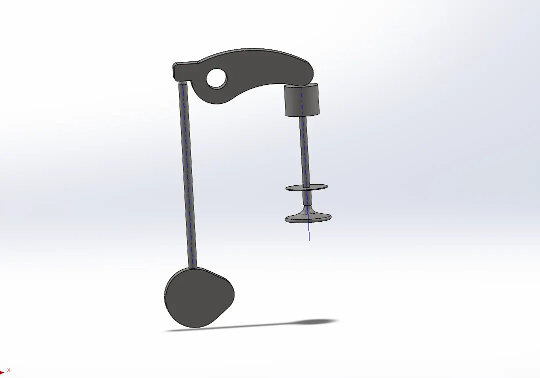
- Assemble all with proper constraints
11mm distance cam assembly:
13.5mm cam assembly:
Result:
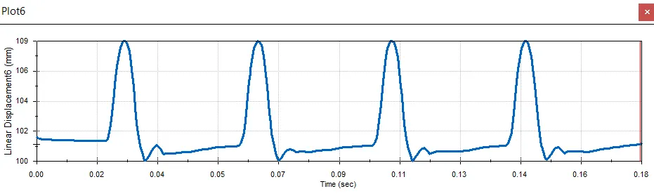
Graph Btw linear displacement vs time.
Motion Analyses:
1.Motor is assigned to cam , RPM : 1500 rpm
2.Contact is assigned between all the components and material dry steel is given.
3.Apply spring between the face of the Valve stem and bottom face of Valve head and assign the following values :
Spring constant : 5 N/mm
Free Length : 45 mm
4.In motion analysis settings , select precise contact option & 1000 frames per second.
Youtube Link: