Multi-body Dynamics: Simulation on IC Engine Valve Train
OBJECTIVE
- To model IC Engine valve train using Solidwork's part design & assembly.
- To simulate IC Engine valve train using Solidwork's Motion Analysis under the following parameters:
| Sl.No | CAM Lift (mm) | Speed (RPM) | Material |
| 1 | 3.5 | 1500 | Cast Carbon Steel |
| 2 | 6 | 1500 |
Cast Carbon Steel |
- To obtain the following from motion analysis:
- Valve Lift
- The contact force magnitude between:
1. Cam and PushRod
2. Pushrod and Rocker Arm
3. Rocker Arm and Valve
- The contact force along X-direction between
1. Rocker Arm and Valve - Explain why the contact force between the Rocker arm and valve varies while measuring with respect to the X direction and measuring with respect to magnitude.
THEORY
- IC valve train is an essential part of IC engine as it controls opening and closing of valves.
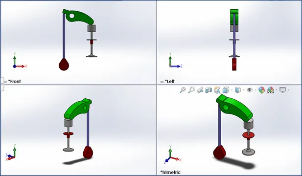
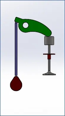
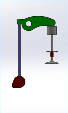
- The valve train consists of a Cam , Push rod, rocker Arm , valve and a spring attached between valve and valve mount.
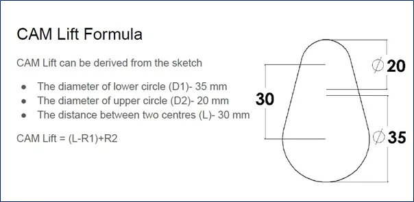
- Cam lift is equal to the sum of the radius of the upper circle and the value obtained from the difference of the distance between two centers and the radius of the lower circle.
CAD MODELLING
- CAM:
- 3.5mm CAM LIFT: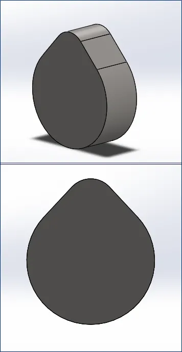
-6mm CAM LIFT: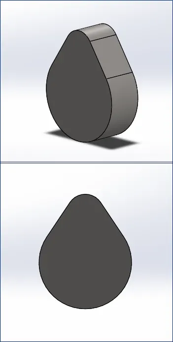
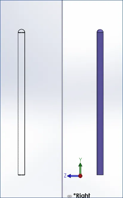
- PUSH-ROD:
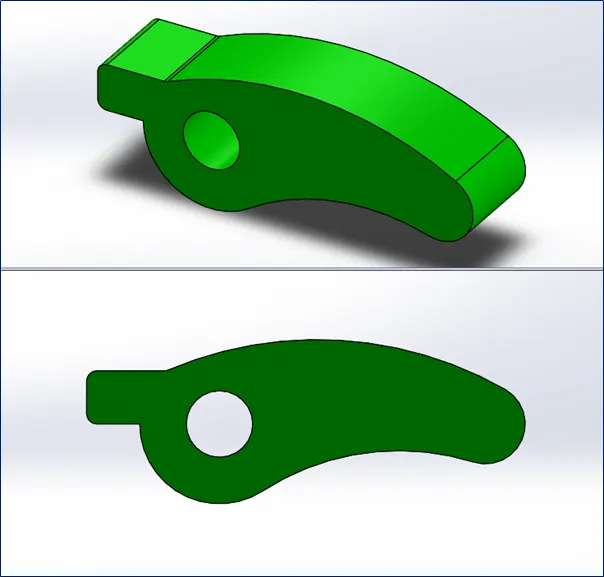
- ROCKER ARM:
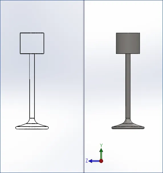
- VALVE:
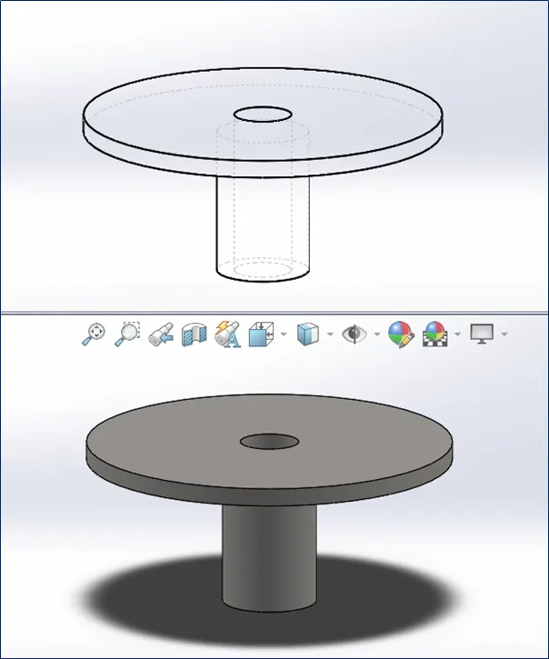
- VALVE STEM:
- ASSEMBLY:
SIMULATION
1. Enable to view the temporary axis.
2. Apply motor to the axis at the circular part of the crank from outside with following parameters:
- RPM:1500
- Clockwise direction
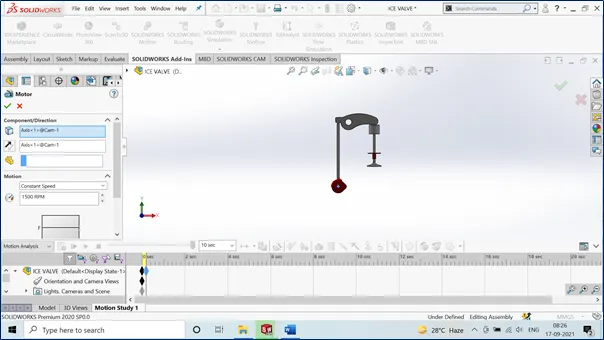
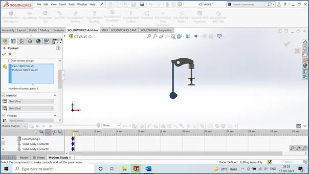
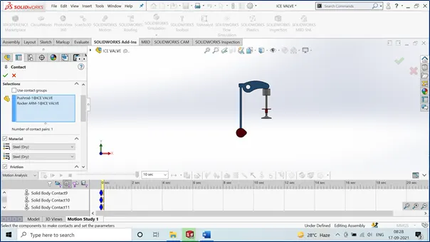
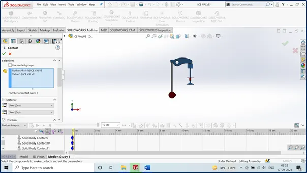
3. Apply contact to the bodies a the following:
- CAM & PUSH-ROD
- PUSH-ROD & ROCKER ARM
- ROCKER ARM & VALVE
4. Apply gravity in Y-Direction
5. Go to settings, update the following parameters:
- Turn on Precise-contact
- FPS:7200
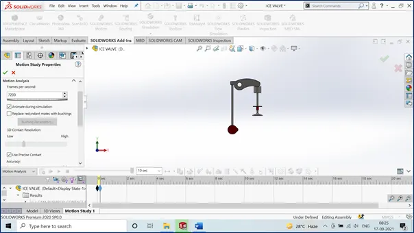
6. Run the Simulation and wait for the analysis. It will take a long time since the process is involved with FPS of 7200 and 1500RPM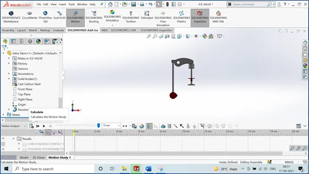
7. Go to Damper and select the 2 regions of the valve and stem valve that face opposite to each other and apply the values:
- K = 10
- Length = 45mm
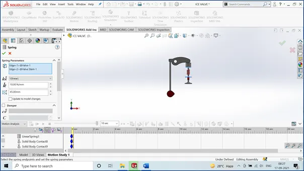
7. Once done, Go to PLOT and select the following parameters:
- FOLLOW THIS PROCESS TO FIND THE CONTACT FORCES MAGNITUDE
- Select, Force/Velocity/Acceleration Tab
- Select, Contact Force
- Select Magnitude
- FOLLOW THIS PROCESS TO FIND THE CONTACT FORCES ALONG X-DIRECTION
- Select, Force/Velocity/Acceleration Tab
- Select, Contact Force
- Select X-Direction
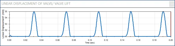
- FOLLOW THIS PROCESS TO FIND THE LINEAR DISPLACEMENT OF THE VALVE
- Select, Force/Velocity/Acceleration Tab
- Select, Linear Displacement
- Select, Magnitude
- Click, OK
8. Plot will be seen now. Then, from the feature tree, right click on results and update the following:
- Rename the plot
- Export the data to excel (OPTIONAL)
9. Next, run the simulation and save the animation file.
10. Save the files with motion analysis, assembly and part files.
*Note: The above process is to be followed 2 times with the following changes:
| Sl.No | CAM Lift (mm) | Speed (RPM) | Material |
| 1 | 3.5 | 1500 | Cast Carbon Steel |
| 2 | 6 | 1500 |
Cast Carbon Steel |
MOTION ANALYSIS
1. Following the above Sl. 01:
- 3.5mm CAM Lift with 1500 RPM of material Cast Carbon Steel:
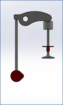
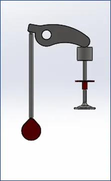
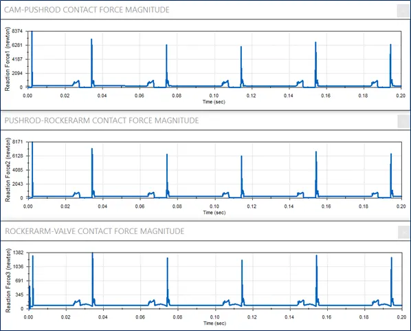
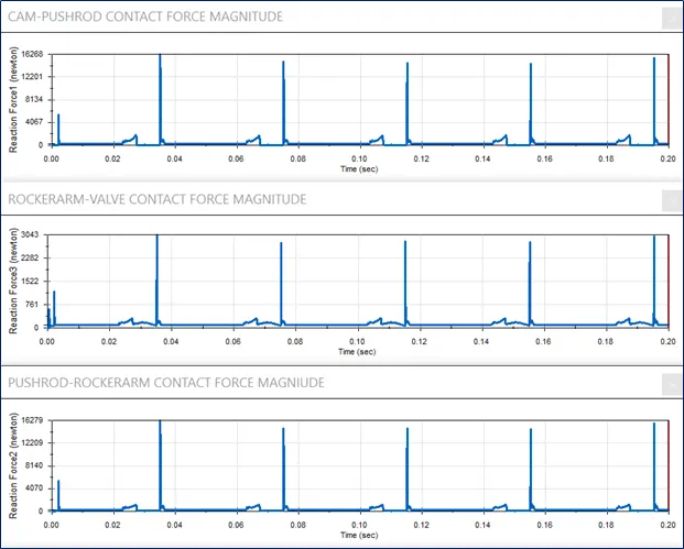
- Comparison of Contact Forces magnitude:
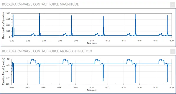
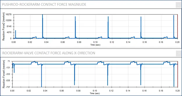
- Comparison of Contact Forces magnitude and Contact Force along X-Direction for Rocker arm & Valve:
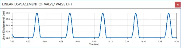
- Linear Displacement of the Valve/ Valve Lift:
- Animation: 3.5mm CAM LIFT-ICE VALVE
2. Following the above Sl. 02:
- 6mm CAM Lift with 1500 RPM of material Cast Carbon Steel:
- Comparison of Contact Forces magnitude:
- Comparison of Contact Forces magnitude and Contact Force along X-Direction for Rocker arm & Valve:
- Linear Displacement of the Valve/ Valve Lift:
- Animation: 6mm CAM LIFT-ICE VALVE
CONCLUSION
- The contact forces exhibited between cam and pushrod is equivalent to the contact force between pushrod and rocker arm.
- This is also true for the contact force between rocker arm and valve.
- From the simulation, we can realise that the contact forces are transmitted almost equally at negligible intervals of time.
- But, we must keep in mind that the spring in the valve might induce a non proportionality due to its unpredictable behaviour at some circumstances.
Why the contact force between the Rocker arm and valve varies while measuring with respect to the X direction and measuring with respect to magnitude?
- The reason for difference in magnitude of force is due to the geometry of rocker arm.
- It has a curved shaped structure which slips away in x direction along with y movement.
- But compared to y movement where the total magnitude is taken into account, x direction magnitude will be less.