MBD Simulation on IC Engine Valve Train by using SOLIDWORKS
AIM :
To modelling the individual parts like cam, push rod, rocker arm, valve and valve stem and assembling them with proper manner. To run the motion analysis with different cam lifts and calculate valve lift for both condition.
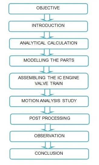
FLOW OF CONTENT/METHODOLOGY :
OBJECTIVES :
1) Create a cam in different cam lift condition, save it in a separate file
2) Assembling a parts with each other for a both cam lift conditions.
3) Preset the parameter for motion study such as motor speed, contact selection, spring stiffness and frames per second.
4) Plotting the graph after completion of calculation like valve lift, contact forces between cam, push rod, rocker arm and valve.
INTRODUCTION :
Valve train :
A valve train is a mechanical system that controls operation of the intake and exhaust valves in an internal combustion engine. The intake valves control the flow of air-fuel mixtureor air alone for direct injected engines into the combustion chamber, while the exhaust valves control the flow of spent exhaust gasses out of the combustion chamber once combustion is completed.
Components :
The valve train consists of all the components responsible for transferring the rotational movement of the camshaft into the opening and closing of the intake and exhaust valves. Typical components are listed below in order from the camshaft to the valves.
i) Camshaft :
A cam shft is a rotating object usually made of steel, that contains lobes, which converts rotational motion to reciprocal motion. Camshaft are used in internal combustion engines to operate the intake and exhaust valves. Camshaft in automobiles are made from steel or cast iron and are a factor in determinig the RPM range of an engine's power band.
The timing and lift profile of the valve opening events are controlled by the camshaft, through use of a carefully shaped lobe on a rotating shaft. The camshaft is diven by the crankshaft, in the case of a four stroke engine rotates at half the speed of the crankshaft. Motion is transferred from the crankshaft to the camshaft most commonly by a rubber timing belt, a metallic timing chain or a set of gears.
ii) Push rod :
Push rod are long, slender metal rods that are used in overhead valve engines to transfer from the camshaft (located in the engine block) to the valves( located in the cylinder head). The bottom end of a pushrod is fitted with a lifter, uponwhich the camshaft makes contact. The camshaft lobes moves the lifter upwards, which moves the pushrod. The top end of the lifter pushes on the rocker arm, which opens the valve.
iii) Rocker arm :
Depending on the design used, the valves are actuated by a rocker arm, finger or bucket tappet. Overhead camshaft engines use fingers or bucket tappets, upon which the cam lobes contact. Overhead valve engines use rocker arms, which are actuated by a pushrod and pivot on a shaft or individual ball studs in order to actuate the valves.
iv) Valves :
Most modern enignes use popet valves type, although sleeve valves, slide valves and rotary valves have also been used at times. Poppet valves are typically opened by the camshaft lobe or rocker arm and closed by a coiled spring called a valve spring.
Valve float occurs when the valve spring is unable to control the inertia of the valvetrain at high engine speeds.
Valve gear mechanism :
Automobile engines are also classified according to arrangements of valves provided in the cylinder heads or blocks. The intake valve and exhaust valve are open or close at correct timings. Movement of valves is actuated by an eccentric cam. This is driven at half the crank shaft speed. The different arrangements of the valve gear mechanisms are as given under
1) Side valve mechanism
2) Over head valve mechanism
3) Overhead inlet and side exhaust valve mechanism
4) Over head cam shaft mechanism
ANALYTICAL CALCULATION :
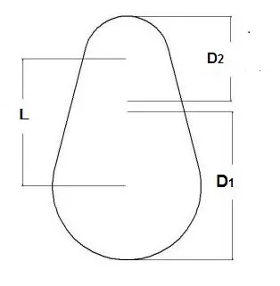
CAM Lift formula :
CAM Lift = ( L - R1) + R2
Where,
L = Distance between the two centers
R1 = Radius of lower circle
R2 = Radius of upper circle
Case 1
CAM lift = 3.5 mm
Diameter of the lower circle , D1 = 25 mm
Diameter of the upper circle , D2 = 10 mm
Radius of the lower circle , R1 = 12.5 mm
Radius of the upper circle , R2 = 5 mm
CAM Lift = ( L - R1) + R2
L = (3.5 - R2) + R1
= (3.5 - 5) + 12.5
= 11 mm
Case 2
CAM lift = 6 mm
Diameter of the lower circle , D1 = 25 mm
Diameter of the upper circle , D2 = 10 mm
Radius of the lower circle , R1 = 12.5 mm
Radius of the upper circle , R2 = 5 mm
CAM Lift = ( L - R1) + R2
L = (6 - R2) + R1
= (6 - 5) + 12.5
= 13.5 mm
MODELLING THE PARTS :
Cam for case 1 :
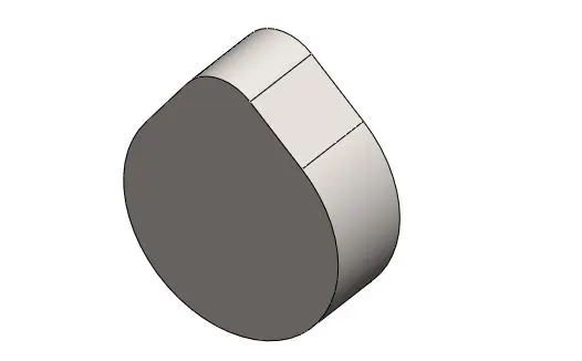
By using circle sketches, create a lower circle at 25 mm diameter and upper circle at 10 mm diameter, both the circle points are to be make vertical to each other. To provide the distance between lower circle center point and upper circle center point are 11 mm. Draw the tangent line from lower circle to upper circle on both circle, trim wanted line from the sketch and convert the 2d sketch into 3d solid part by using extrude boss base option from the mid plane. In this cam lift is 3.5 mm
Cam for case 2 :
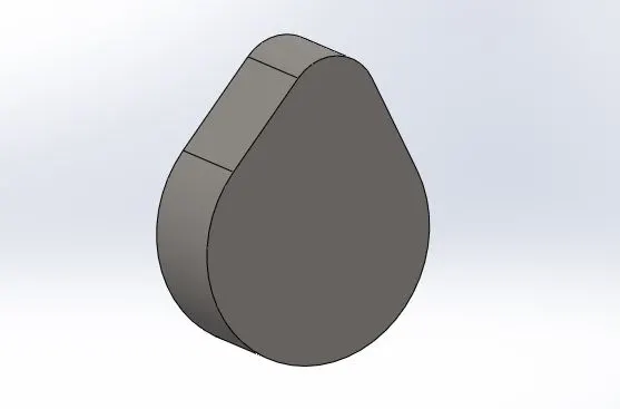
The case 1 procedure is same for creating the case 2 cam as well. But, we use the length of center distance is 13.5 mm instead of 11 mm. The cam lift is 6 mm
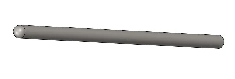
Push rod :
Draw the 2d sketch with appropriate dimension and convert into solid model from drawn 2d sketch by using revolve option.
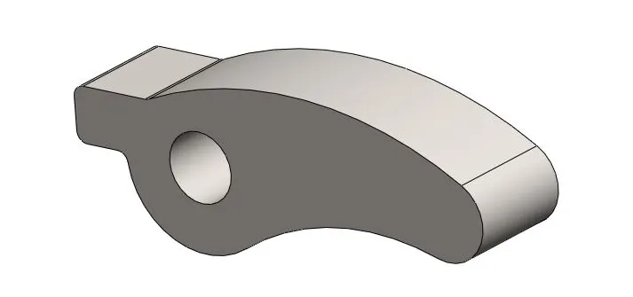
Rocker arm :
Draw a 2d sketch by using asusual options are circle, arc, line, make horizontal, fillet and trim. Covert the 2d sketch to solid model on z direction with appropriate length.
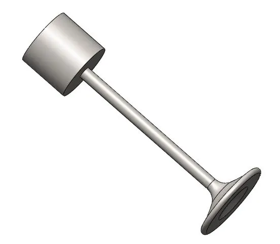
Valve :
A valve is a sysmetrical in natural, to draw a 2d sketch and revolve it about an reference center axis.
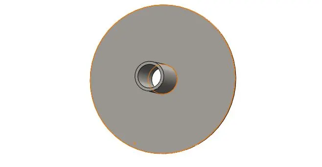
Valve stem :
A valve is a sysmetrical in natural, to draw a 2d sketch for which valve stem and revolve it about an reference center axis.
ASSEMBLING THE IC ENGINE VALVE TRAIN :
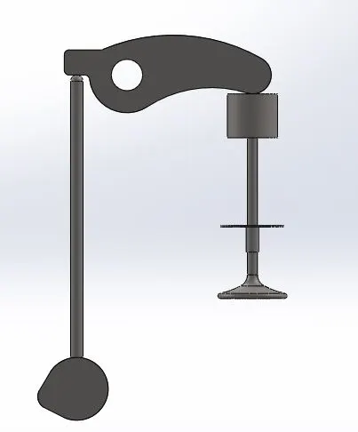
1) Import the all parts in the assembly section such as cam, push rod, rocker arm, valve and valve stem. First of all, Select the assembly front plane and rocker arm front plane is mate together. Select the rocker arm axis to make coincident to assembly top plane, similarly for assembly right plane also. Now, a rocker arm is rotate about a axis.
2) Remaining all parts should coincident to assembly front plane. Select the valve axis and valve stem axis, keep coincident with other. Select the push rod axis and assembly right plane to provide the line distance at 20 mm, Similarly for cam axis and assembly right plane at distance.
3) Similarly, provide the line distance of 60 mm instead of 20 mm from the assembly right plane to valve axis.
4) Select the rocker arm axis and cam axis to provide vertical line distance at 125 mm.
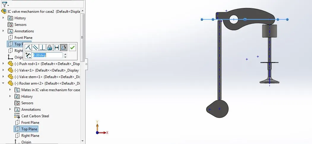
5) Before going to motion analysis study, we check the constraints like angle between the assembly top plane and rocker ar top plane at 0 degree.
6) Change the material property of whole model into cast carbon steel.
MOTION ANALYSIS STUDY :
1) Addins the Motion study option in the solidworks, change the option into motion analysis from basic motion. Set the power to cam axis at 1500 RPM on clockwise rotation.
2) Provide the contact selection between the cam, push rod, rocker arm, valve and valve train, with define the dry steel material.
3) Give the frames per second is 9000 with precise contact.
4) Set the linear spring between valve stem top face edge and valve inner flat side edge, a spring stiffness is 20 N/m and free length is 45 mm for spring get pretensioned. See the below figure, the spring loos red color that means spring have pretensioned between valve and valve stem.
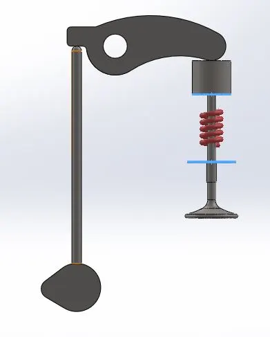
5) We have a two cases, calcuation have been run separately on both case and plotting out also separately.
POST PROCESSING :
CASE 1
A center distance between upper circle and lower circle has been 11mm, the result of cam lift is 3.5 mm
Linear displacement of push rod :
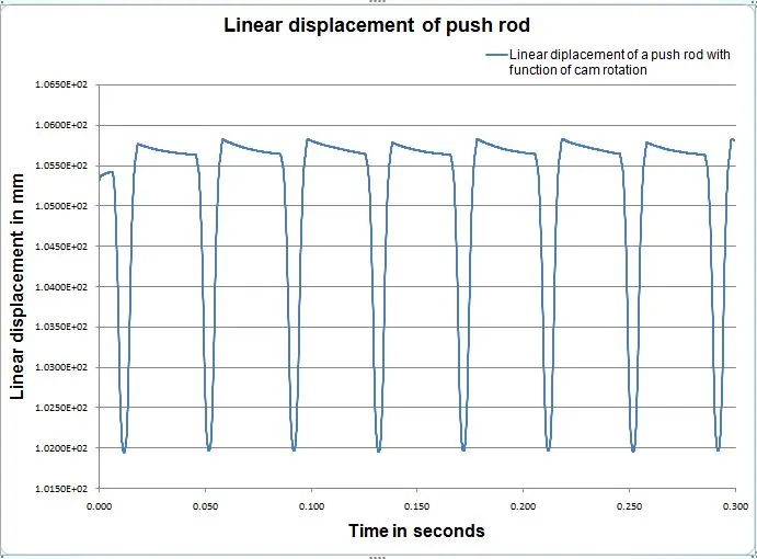
A push rod linear displacement is equal to cam lift. The initial position of push rod is 105.5 mm to 105.7 and final position of push rod is 102.0 mm, the difference is almost 3.5mm. The linear displacement of push rod is acceptable and same pattern is repeating over the time duration.
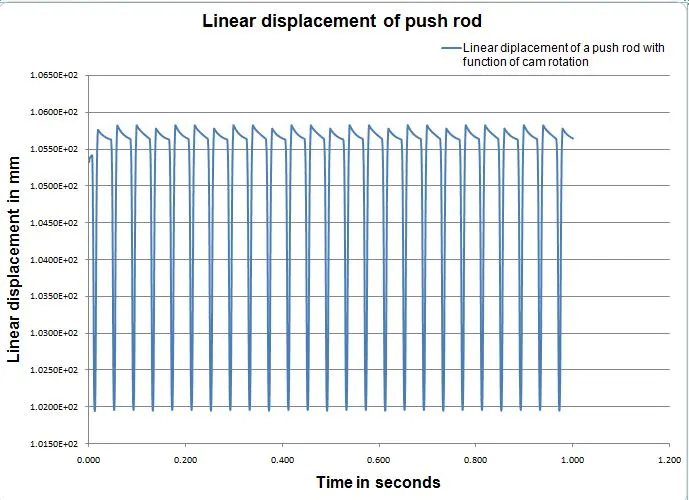
A cam lobe push the push rod on positve y direction, for each rotation of cam time had taken around 0.040 seconds
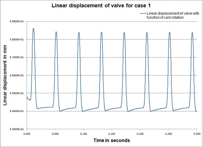
Linear displacement of valve
Linear displacement of the valve is higher than the linear displacement of the push rod. Because, the distance between push rod axis and rocker axis is small at 25 mm, the distance between the rocker arm tip and rocker axis is 50 mm. So, that linear displacement distance is higher than the push rod linear displacement distance.
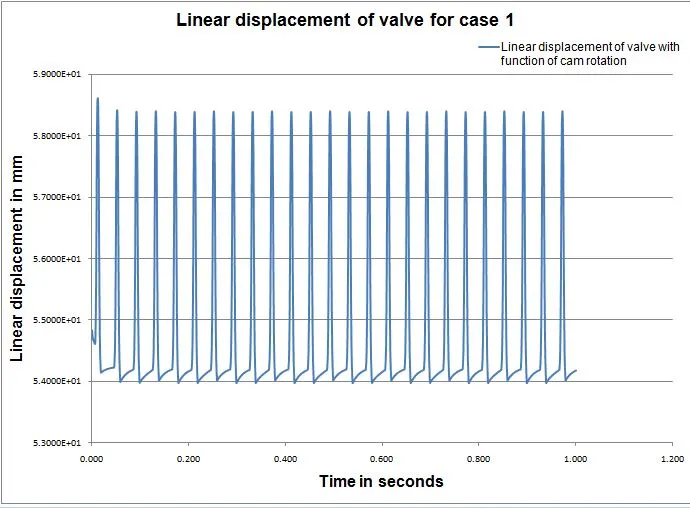
Initial position is 54 mm and final position is around 58.5 mm. The range is high compared to push rod range.
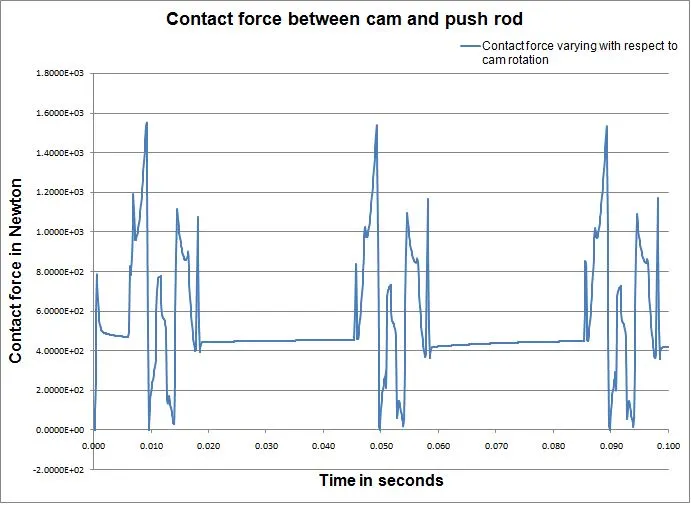
Contact force betweeen cam and push rod :
A contact force between cam and push rod is repeated the same profile over the time duration. The lines are drawn closely each other, it unable to read properly.
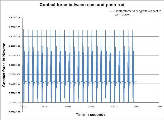
A equilibrium force is maintain around 440 N at which follower not flow over the lobes surface. When the follower flow around the lobe profile, the force can vary with respect to cam rotation. Initial push force is high, because induced resistive force is high.
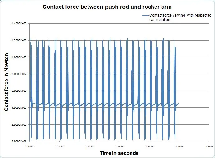
Contact force between push rod and rocker arm :
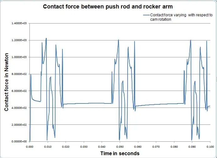
The equilibrium force is constant at time of flow around the base circle profile. A force has been varied with respect to cam rotation over the time period.
The ups and downs happens at which follower flow around the cam lobes over the each rotation.
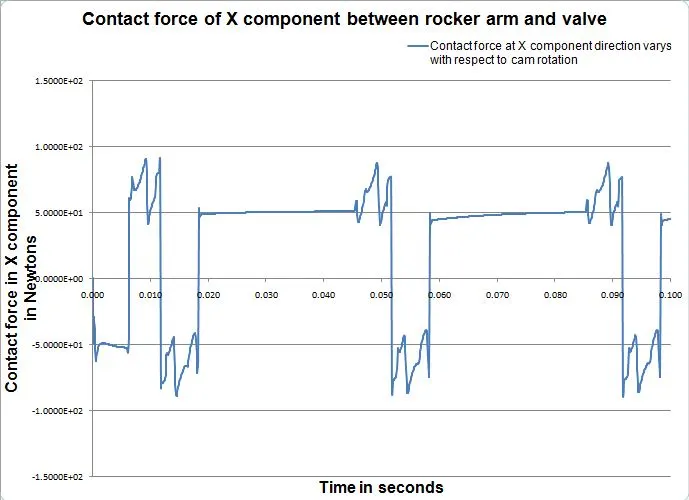
X direction contact force between rocker arm and valve :
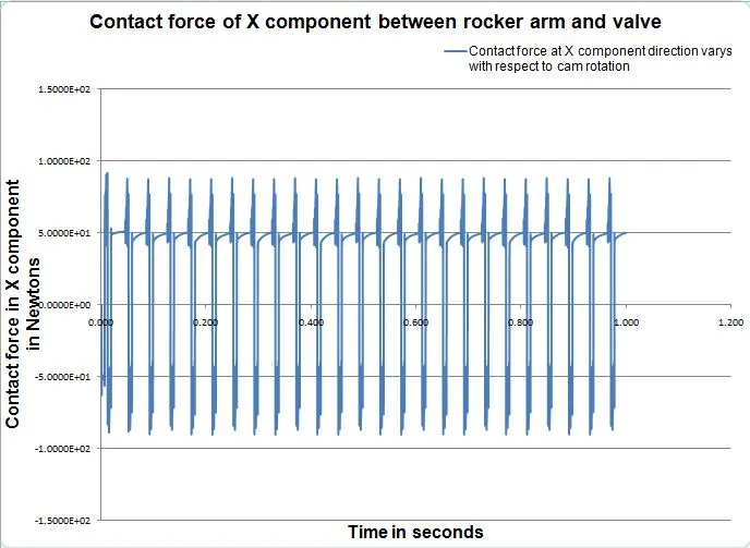
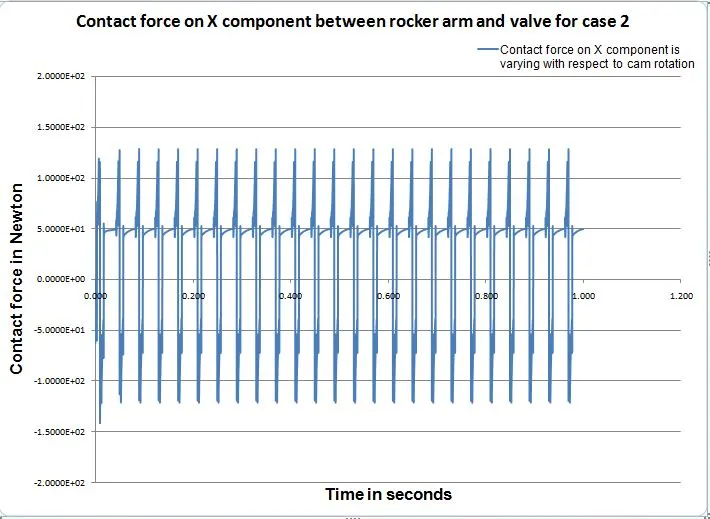
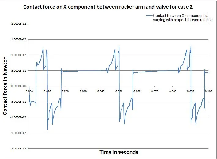
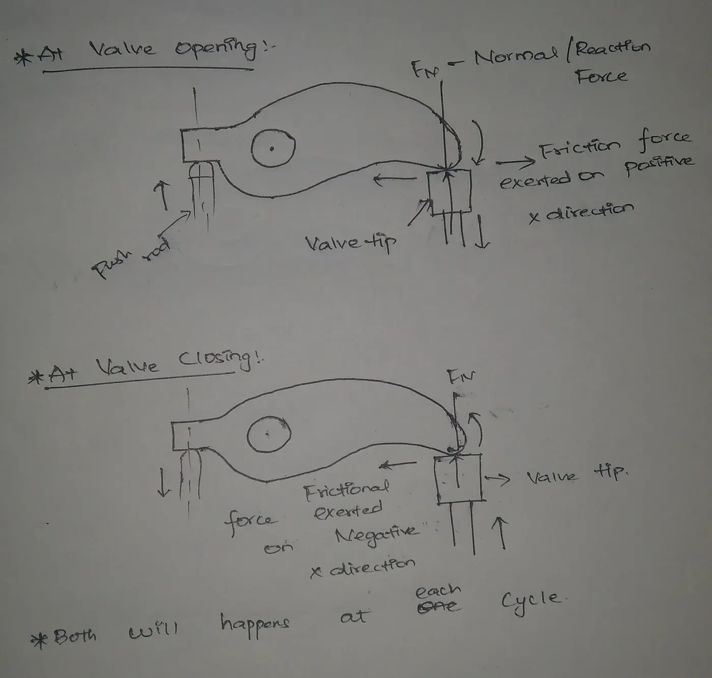
Contact force between the rocker arm and valve along the x direction is varied positve to negative or vice versa. Because, when a valve is opening at the time rocker arm gets rotates on clockwise direction with the normal force, due to this frictional force exerted an opposite direction or positive X direction direction or Otherword, the rocker arm slides over the tip in right to left from the frontal view, a frictional force exterted away on positive x direction. Also, vice versa for when valve gets closing time.
Y direction contact force between rocker arm and valve :
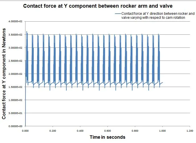
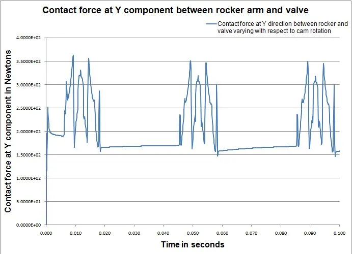
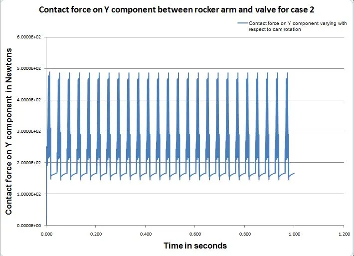
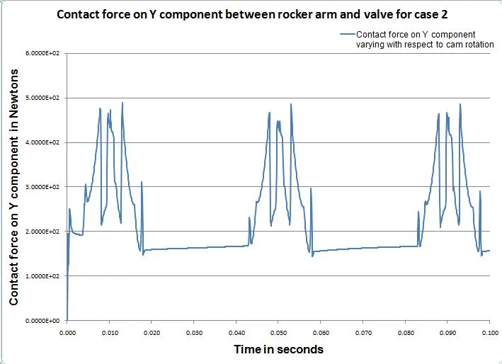
Y direction force is always higher than the X direction force. Intially, we have spring tension force and corresponding resistive force fron rocker arm. The Y direction force is predominant for which calculate the magnitude contact force.
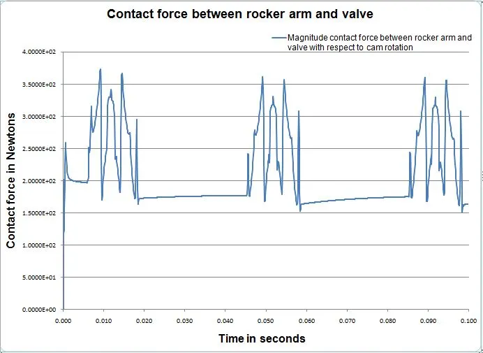
Magnitude Contact force between rocker arm and valve :
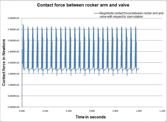
We have a two components for which calculate the magnitude force, one is X direction components and another one is Y direction component. We have a equation for calculating the magnitude contact force.
Magnitude contact force = `sqrt ((Vx)^2 +(Vy)^2`
Take up the x component contact force and also Y component contact force at the instantenous points and plot it correspondingly together.
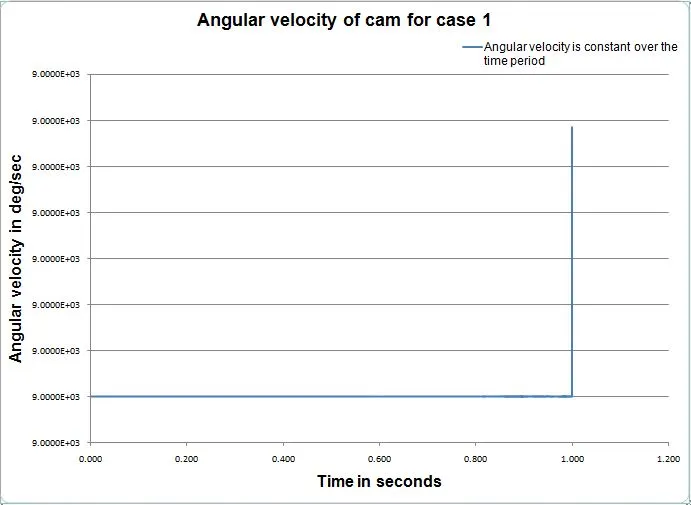
Angular velocity of cam for case 1 :
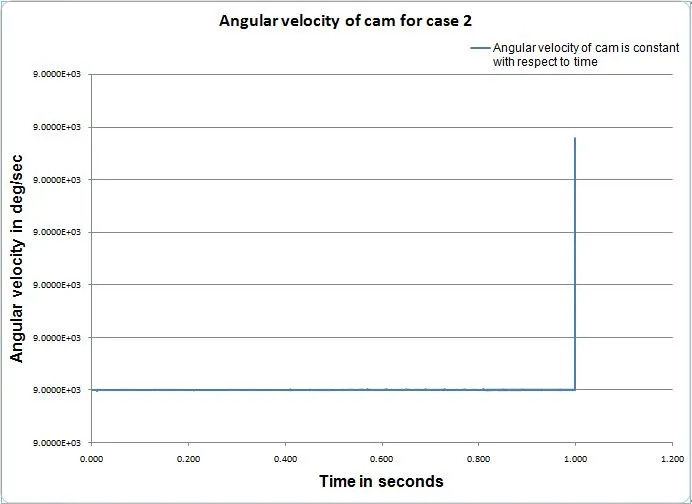
A angular velocity of cam is 1500 RPM for both cases, by using the RPM we actually calculate the angular velocity.
Youtube link for case 1 : https://www.youtube.com/watch?v=BRo1_O6zwNQ
CASE 2
A center distance between upper circle and lower circle has been 13.5 mm, the result of cam lift is 6 mm
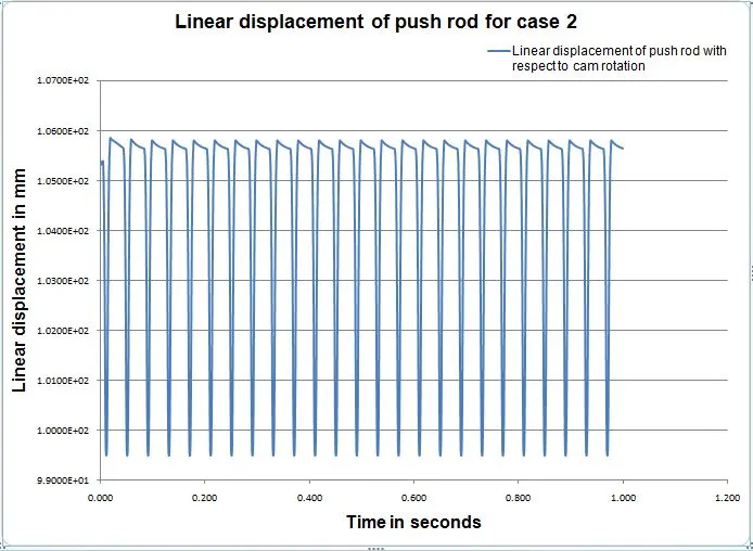
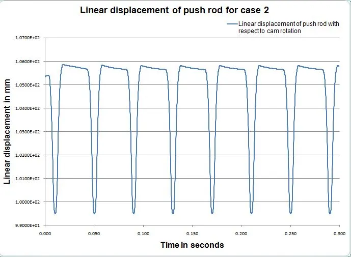
Linear displacement of push rod :
A push rod linear displacement is equal to cam lift. The initial position of push rod is 99.5 mm and final position of push rod is 105.9 mm, the difference is almost 6mm. The linear displacement of push rod is acceptable and same pattern is repeating over the time duration.
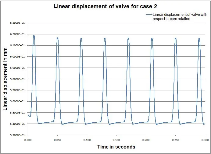
Linear displacement of valve :
Linear displacement of the valve is higher than the linear displacement of the push rod. Because, the distance between push rod axis and rocker axis is small at 25 mm, the distance between the rocker arm tip and rocker axis is 50 mm. So, that linear displacement distance is higher than the push rod linear displacement distance.
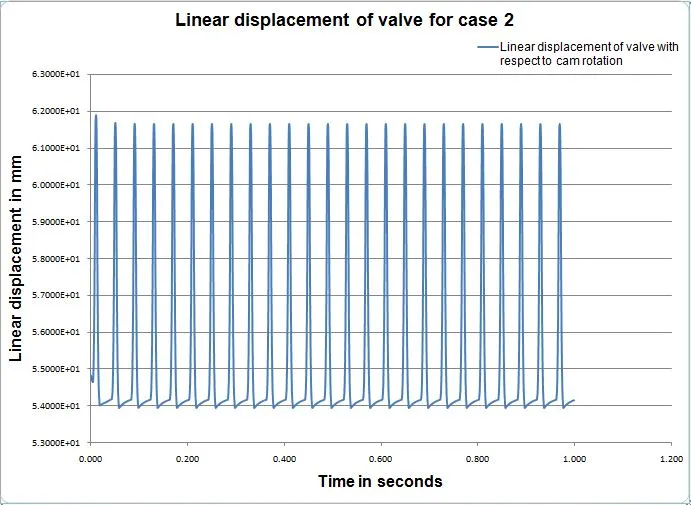
Initial position is 54 mm and final position is around 62 mm. The range is high compared to push rod range.
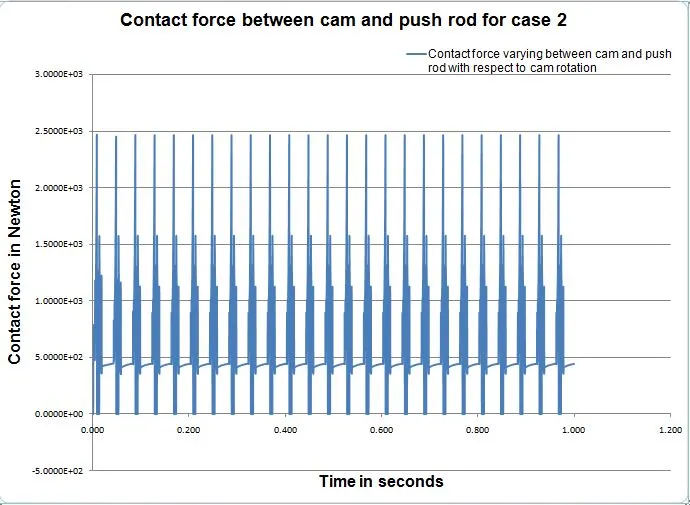
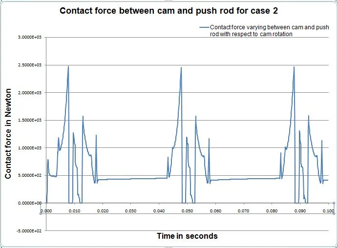
Contact force between cam and push rod :
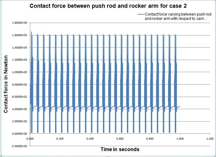
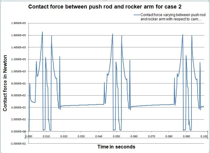
Contact force between push rod and rocker arm :
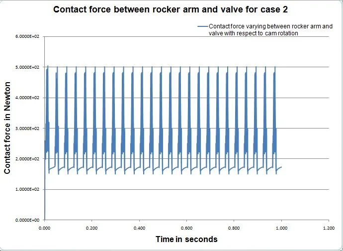
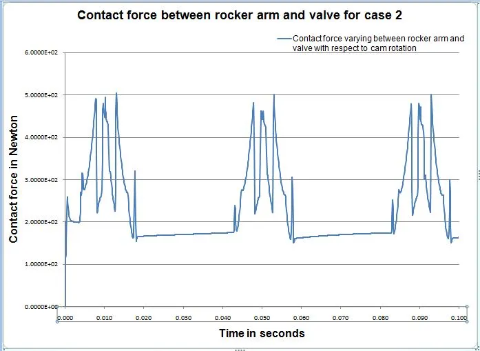
Magnitude Contact force between rocker arm and valve :
X direction contact force between rocker arm and valve :
Y direction contact force between rocker arm and valve :
Angular velocity of cam for case 2
Youtube link for case 2 : https://www.youtube.com/watch?v=gkRyvEd53mQ
OBSERVATION :
1) A spring pretension force is pull away the valve inner face and valve stem face. That force replicate into a normal force.
2) A cam lift is equal to linear displacement of push rod for the both case.
3) A linear displacement of valve is higher than the push rod displacement. Reason is distance between the push rod axis and rocker arm axis is 25 mm. The distance between rocker arm axis and valve axis is 75mm. Moment is same, but the force is different due to length is different along the x direction.
4) When the valve opening, the frictional force is goes on towards positive X direction. When the valve closing, the frictional force is goes on towards negative X direction. Look at the below figure.
5) The normal force is exerted on Y direction, it has always keep on some forces with them.
6) The magnitude of contact force is always positive forces, because y direction force is high. Moreover, normal force on Y direction is equal to magnitude of contact force.
CONCLUSION :
The motion analysis has been successfully done and the post processing of linear displacement of push rod, valve, contact forces between cam, push rod, rocker arm and valve are satisfied,
REFERANCE :
1) https://en.wikipedia.org/wiki/Valvetrain
2) https://en.wikipedia.org/wiki/Camshaft
IC ENGINE VALVE TRAIN MODEL LINK : https://drive.google.com/drive/folders/1ubyiFJgTt8N9lsUPUzzkscMQ9MfTRKj8?usp=sharing