MBD Simulation on IC Engine Valve Train
Aim: To create the IC engine valve train mechanism and perform a motion study on it after applying the given conditions.
Theory: For the formation of the IC engine valve train mechanism, we mainly need 5 components which are
- Cam
- Pushrod
- Rocker arm
- Valve mount
- Valve
These components assembled would form the valve train mechanism which would let the flow of air and fuel into the cylinder and help the process of combustion.
The individual components are as follows.
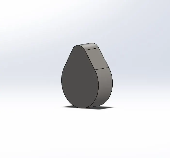
1. Cam: The cam is one of the most important components in the IC engine as it helps in converting the rotational motion into reciprocal motion and makes the mechanism of valve opening and closing possible. These operate the intake and exhaust valves of the IC engine. These are generally made of steel or cast iron. The lobe like structure is created by drawing two circles and joining them with lines tangent to both of them. changing the distance between them or changing the circle diameters, the cam lift changes. The final model of the cam looks as shown below.
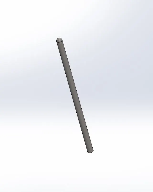
2. Push Rod: Pushrod is a component that is seen in between the cam and the rocker arm and transmits the reciprocating motion to the valve that operated the engine allowing fuel and air to get in and exhaust to get out. These are usually made of steel with the semi-spherical surface on one end. The following is the final image of the pushrod made according to the dimensions.
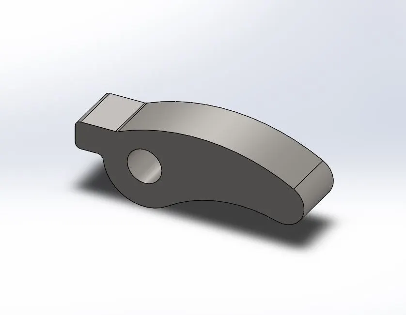
3. Rocker arm: Rocker arm is an oscillating lever that converts the radial movement of the cam into linear reciprocating movement of the valve. It obtains its oscillating motion from due to the spring attached to the valve which pushes it back after compression. Rocker arms are usually made of steel or aluminum. The rocker arm is modeled according to the dimensions is shown below.
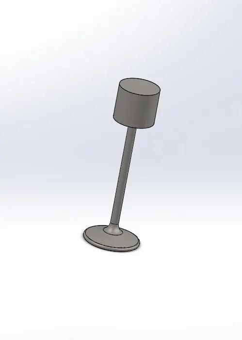
4. Valve: Valves are used to open and close the intake and exhaust ports of the IC engine allowing in the fuel-air mixture and letting out the exhaust gasses. The valve is a disc type structure with a long rod attached to it known as the valve stem. Valves are usually made of alloys that have special heat resistance and anti-corrosive properties to withstand the combustion conditions. The final model of the valve is shown below.
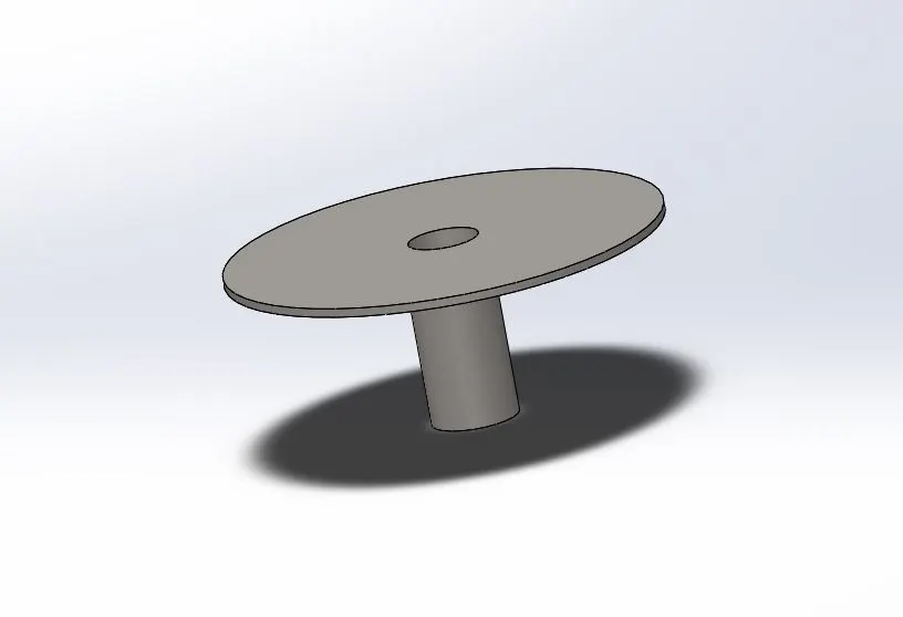
5. Valve mount: Valve mount is a component of the valve train mechanism that restricts the movement of the valve in a line. The final model of the valve mount is shown below.
Introduction: The following conditions are given in order to create a motion study and analyze the results.
- We need to model the parts and assemble them in SolidWorks.
- Run the simulation using the below parameters
| Sl.No | CAM Lift (mm) | Speed (RPM) | Material |
| 1 | 3.5 | 1500 | Cast Carbon Steel |
| 2 | 6 | 1500 |
Cast Carbon Steel |
We need to obtain the
- Valve Lift.
- The contact force between
- Cam and Push Rod
- Pushrod and Rocker Arm
- Rocker Arm and Valve
It needs to be explained why the contact force between the Rocker arm and valve varies while measuring with respect to the X-direction and measuring with respect to magnitude.
Also, the information about the cam lift is provided as follows:
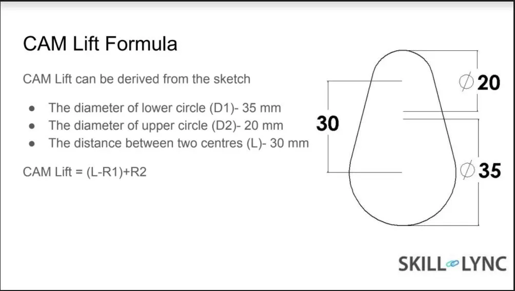
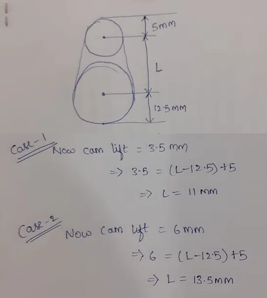
Using the above formula we derive the value of L in both the cases of cam lift being 3.5mm and 6mm as follows and apply them to the designed parts of our assembly to obtain results:
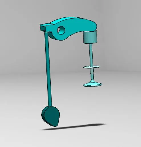
Motion Study Setup: All the parts that are designed in SolidWorks and showcased above in the theory part are now assembled by giving a few constraints to the parts and final assembly looks as shown below.
Now the given 2 cases are executed by substituting the value of L in the Cam part design and applied to the assembly. Later the results are taken in each case to analyze. The following are the pictures of both the cases being created.
Case 1:
As we know from the given data that the radius of the larger circle is R1=12.5mm and the radius of the smaller circle is R2=5mm and Cam lift = 3.5 which gives us L=11mm (shown in the calculations picture from the introduction). The following sketch is created to get the final model and apply it to the assembly.
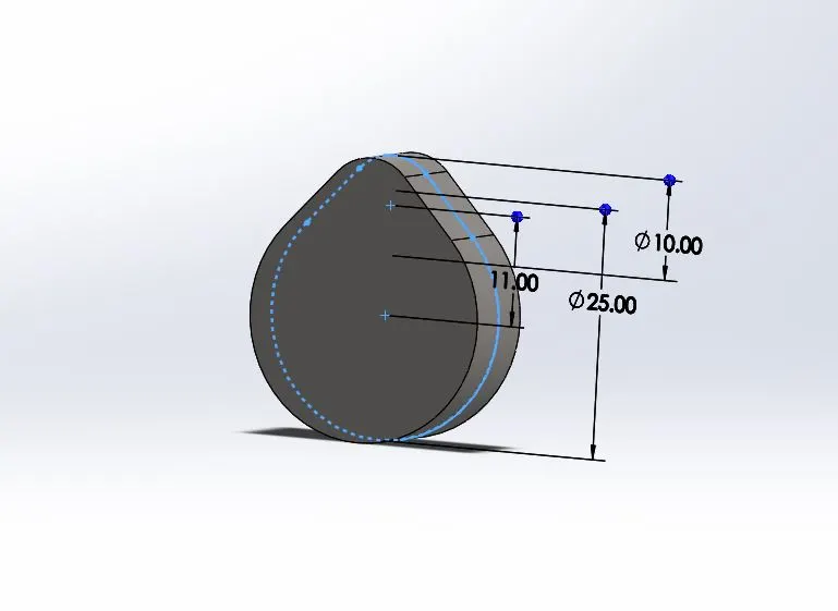
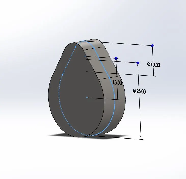
Case 2: As we know from the given data that the radius of the larger circle is R1=12.5mm and the radius of the smaller circle is R2=5mm and Cam lift = 6mm which gives us L=13.5mm (shown in the calculations picture from the introduction). The following sketch is created to get the final model and apply it to the assembly.
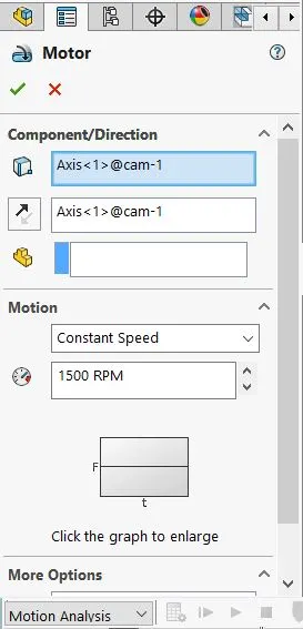
Also according to the given data, we assign a motor to the axis of the cam and give is a speed of 1500 rpm as follows:
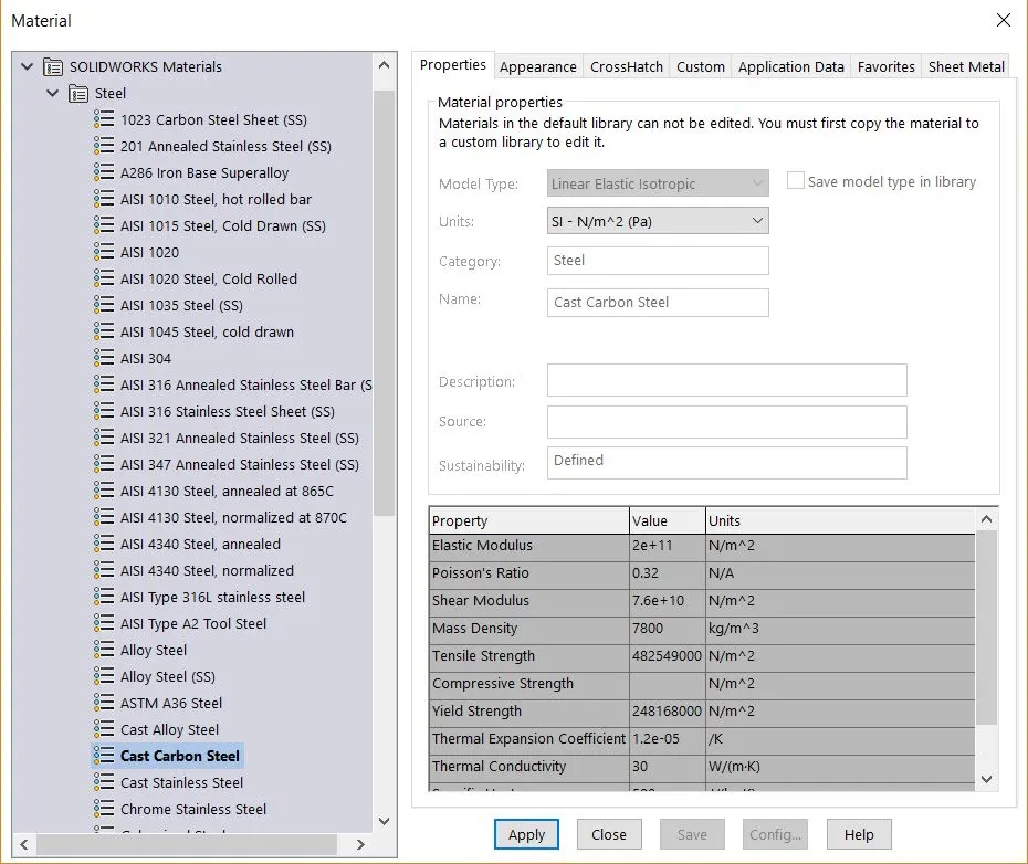
Also all the contacts are given and the material choice of cast carbon steel is applied to all the parts as shown below:
In order to obtain the plots in a way that we can analyze, the frame rate is changed to 9000fps in both cases. This is because the speed of cam is 1500rpm and converting it into degrees per sec we get 9000deg/sec. This is shown below:
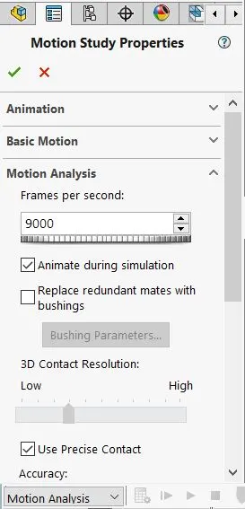
With all these, we have set up everything ready to obtain plots and analyze them in both cases.
Motion Study:
After setting up the assembly in motion study and applying all the given conditions, plots of linear displacement and contact forces are created and analyzed.
Case 1:
The linear displacement of Valve to analyze valve lift:
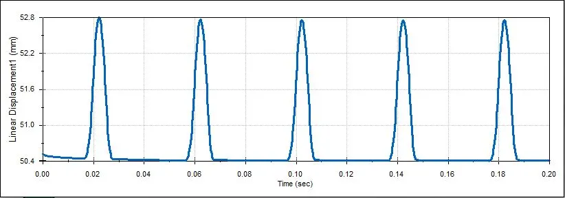
From the plot, we can see that the valve lift is the difference between the lowest and highest value on the y-axis which is around 2.4mm. The valve lift varies with 50.4-52.8mm range with the cam lift being 3.5mm in this case.
The contact force between Cam and Pushrod:
Here we can see from the plot that the contact force increases and reaches its highest spike as the cam rotates and the smaller lobe reaches the top. There is a maximum force of around 4342N observed during the contact period of the cam and the pushrod. There are places in the plot where the contact force is minimum when the cam reaches its peak during its rotation.
The contact force between Pushrod and Rocker arm:
Here the contact force initially is quite stable and it reaches its peak when the pushrod is pushing the rocker arm against the spring force of the valve and again decreases as the spring pushes back the rocker arm which in turn pushes the pushrod into place. At the time when the bigger lobe of the cam is in contact with the pushrod, the contact force is minimum between the pushrod and rocker arm. The contact force is to be seen at its maximum of around 4414N.
The contact force between the Rocker arm and valve with respect to magnitude:
Here the contact force between the rocker arm and the valve begins with zero and increases slowly to reach a maximum value of around 892N. The contact force increases as the rocker arm increases pressure on the valve compressing the spring. After compressing the spring completely the valve pushes back the rocker arm to the initial position.
The contact force between the Rocker arm and valve in x-direction:
The difference between the plots of this contact force as magnitude and x-direction is that here we see negative forces in play as well. This is because the forces are considered in only x-direction and the valve pushes the rocker arm back due to the spring and this causes the forces to be considered negative here. Friction also comes into play here.
Animation of the mechanism, in this case, is shown below:
Case 2:
The linear displacement of Valve to analyze valve lift:
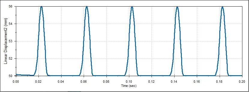
Valve lift here is seen to be around 6mm as it can be considered as the difference of highest and lowest values.
The contact force between Cam and Pushrod:
The Contact force is seen to have a similar pattern but increases drastically as the cam lift increases. the highest value is seen to be around 14898N.
The contact force between Pushrod and Rocker arm:
The maximum value of the contact force here is seen around 15063N.
The contact force between the Rocker arm and valve with respect to magnitude:
The maximum value of the contact force here is seen around 2877N
The contact force between the Rocker arm and valve in x-direction:
The reason for the variation of the plot for magnitude and x-direction of same contact force is similar to the first case and the pattern is also similar. just that the values vary.
Animation of the mechanism, in this case, is shown below:
Conclusion:
Finally, the conclusion with both cases is that as the cam lift increases the contact forces increase drastically and it should, in turn, affect the frictional forces. So the optimum cam lift is desirable and increasing the cam lift is not a great way to design the valve train mechanism. Cam lift of 3.5mm seems to be more ideal than the cam lift of 6mm.