MBD Simulation on IC Engine Valve Train
Aim:
The aim of this project is to make an analysis of the contact forces between the cam, pushrod, rocker arm and valve of an IC engine and also to make a plot of the valve lift for a cam lift of 3.5mm and 6mm. For the design and the multi-body dynamic analysis solidworks is used in this case.
Introduction- Brief of the components involved:
A valve train of an IC engine consists of a cam, pushrod, rocker arm, spring and a valve. These components are designed initially used solidworks.
Cam:
Cam is the component that converts rotary motion into linear motion. The linear motion depends on the profile of the cam over which the follower rests.
Pushrod:
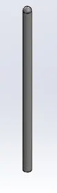
Pushrod is the follower in this case. This translates the linear motion of the cam to the rocker arm.
Rocker arm:
This converts the axis of motion of the pushrod to a perpendicular axis. The tip of the rocker arm rests over the valve head.
Valve:
The tip of the rocker arm rests over the valve head. This valve covers the inlet and outlet openings of an IC engine.
Valve mount:
Valve mount is placed between the valve head and the valve. This is used to mount the valve spring .
Calculation of cam lift:
A MATLAB program was written to calculated the center distance from cam lift with the provided formula.
MATLAB code:
% A function to calculate the center distance from CAM lift to design an IC engine valve train
function l =center_dist(lift,r1,r2);
% l is the center distance
%lift is CAM lift
%r1 is radius of lower circle
%r2 is radius of upper circle
l =(lift+r1)-r2
end
Setup in solidworks:
These components are assembled by providing necessary constrains. Once the components are assembled, physical dynamics is used to set the components initially in place so that there is no collision in the motion study. In the motion study, a motor is set up at the central axis of the cam. Solid body contacts are established between the various components. Finally, a spring is set up between the valve head and the valve mount.
Cam design (for 3.5mm and 6mm lift):
Motion study setup:
Results:
The motion study was conducted for 2 separate cam designs with cam lifts of 3.5mm and 6mm respectively. For both these cases, the materials used was cast carbon steel and the speed of rotation of the cam is 1500 rpm.
Results for 3.5mm cam lift:
1. Valve lift
2. Contact force between the cam and pushrod
3. Contact force between pushrod and rocker arm
4. Contact force between rocker arm and valve head
5. Contact force between rocker arm and valve head - X magnitude only
It can be seen that the contact force between the rocker arm and valve head differs when it is measured as a raw magnitude and X axis magnitude only. This can be attributed to the fact the the motion of the rocker arm occurs in the X axis as well as Y axis. So the measuring only the magnitude gives the resultant magnitude. Whereas measuring magnitude only in X direction does not account for the forces in the Y direction.
Results for cam displacement of 6mm
1. Valve lift
2. Contact force between the cam and pushrod
3. Contact force between pushrod and rocker arm
4. Contact force between rocker arm and valve head
5. Contact force between rocker arm and valve head - X magnitude only
Conclusion
Thus the IC engine valve train was designed, assembled and analyzed using solidworks. The contact forces and valve displacements were plotted for a cam lift of 3.5mm and 6mm.