MBD Simulation on IC Engine Valve Train
AIM: To perform the MBD analysis of an IC engine valve train
TASKS:
- Model the parts and assemble them in SolidWorks
- Simulate for following parameters
|
Sl.No |
CAM Lift (mm) |
Speed (RPM) |
Material |
|
1 |
3.5 |
1500 |
Cast Carbon Steel |
|
2 |
6 |
1500 |
Cast Carbon Steel |
- Obtain the following results
- Valve Lift.
- The contact force between
- Cam and Push Rod
- Pushrod and Rocker Arm
- Rocker Arm and Valve
The cam lift is given by:
COMPONENTS:
- Cam
Cam 1
Cam 2:
- Pushrod
- Rocker arm
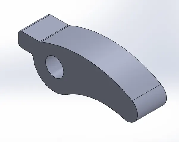
- Valve
- Valve stem
Final assembly:
Mates:
- Align all the individual part front planes with the front plane of the assembly
- Provide distance mate for the
- Axis of push rod- right plane
- Axis of valve stem- right and top planes
- Coincident mate between faces of valve stem (inner) and valve (outer)
PROCEDURE:
- Create all individual part models as listed above
- Open an assembly file and perform the assembly by giving relevant mates
- Assign the cam as motor with rpm 1500
- Assign contact bodies for bodies in contact
- Setup the required plots
- Calculate solution
Results:
- Lift
- Contact force: Pushrod-cam
- Contact force: Pushrod- Rocker arm
- Contact force: Rocker arm- Valve
Case 2:
- Lift
- Contact force: Pushrod-cam
- Contact force: Pushrod- Rocker arm
- Contact force: Rocker arm- Valve
Using a cam designed to provide greater lift, has a uniformly increasing and decreasing reaction force between the cam and the push rod. Which means that the movement of the cam over the push rod would be smooth compared to the other cam.
The displacement of cam appears to be coherent with the designed lift.