MBD Simulation on a Piston Assembly
AIM : To model all the parts of piston assembly and then assemble them in SolidWorks and run motion analysis.
OBJECTIVE :
- To create 3D model of different components of piston assembly,
- To run motion study analysis for the following cases -
| S. No. | Wrist Pin Offset | Crank Speed (Rpm) | |
| 1. | "0" mm | 2000 | |
| 2. |
|
2000 | |
| 3. | 10 mm Negative | 2000 |
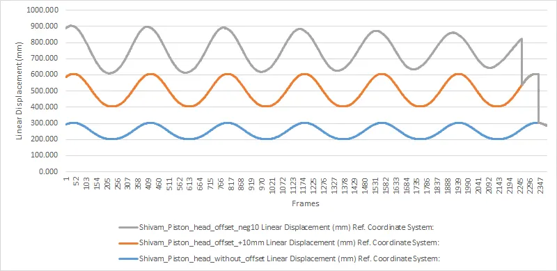
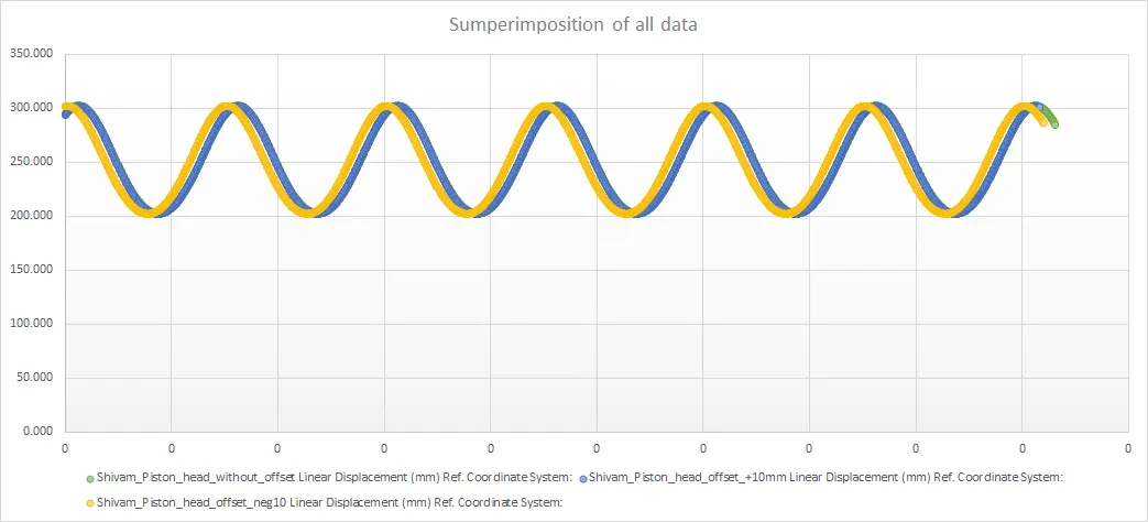
- To plot the Linear displacement of the Piston Head in all the three cases and then superimposing graphs by exporting them to Microsoft Excel.
THEORY :
Piston : The assembly of the piston, connecting rod and crank shaft in an engine behaves like a mechanism during the working of the engine.The piston makes the crankshaft to turn by utilizing the energy supplied to it by the combustion of the fuel. It is cylindrical in shape and reciprocates inside the cylinder. Pistons are provided with groves near the top and provide an air tight fit. The pistons do not allow the high pressure mixture from the combustion chambers into the crankcase. The piston has four strokes in total, two upside and two down. During the intake stroke, the piston moves down and the cylinder is filled with air fuel mixture. The upward stroke compresses the mixture and as it reaches near the top position, the ignition of the fuel causes the piston to move downwards, the third stroke. During the fourth stroke, the piston moves upward and pushes the burnt gases to the exhaust system. The piston operates under high pressure and high temperature.
Connecting rod : The connecting rod links the piston and the crankshaft. It has a hole at the upper end (small end) and is connected to the piston by the wrist pin. The lower end, also called as Big end, is attached to the crankshaft. The small end is press fit and can swivel in the piston. The Connecting rods are usually made of alloy steel, Titanium and sometimes with aluminum. They are not rigidly fixed at either end, so that the angle between the connecting rod and the piston can change as the rod moves up and down and rotates around the crankshaft. The big end is connected to the bearing journal on the crank throw. The connecting rod is under a lot of stress with every rotation. High factor of safety is provided as the failure of the connecting rod is very likely under such heavy stresses. Attention has to be paid to eliminate the stress risers in the connecting rod during production. Also, the bolts should be tightened with proper torque.
Crankshaft : The turning motion to the wheels is provided by the crankshaft, which converts the reciprocating motion of the pistons into a rotary motion. The crankshaft is usually either alloy steel or cast iron. Crankshafts are connected to the pistons by the connecting-rods. The crank shaft has crank throws which are offset from the crank. The big end of the connecting rod is attached to it. The crank shaft is connected to a flywheel to reduce the torsion vibrations.
Gudgeon pin : In internal combustion engines, the gudgeon pin (UK, wrist pin or piston pin US) connects the piston to the connecting rod, and provides a bearing for the connecting rod to pivot upon as the piston moves.
PROCEDURE :
- 3D Modelling of different components :
- At first different components are designed according to dimensions provided,
- 1. Design of Crank -
- 2. Design of Piston Head -
- 3. Design of Connecting Rod -
- 4. Design of Wrist Pin -
- 5. Design of End Cap -
- Assembly of all the Components :
- The components modelled are now assembled by importing into assembly. The first component inserted is made to float from being fixed.The temporary axes should be selected for the ease in assembling. All the components are assembled with necessary constraints, so that desired motion can be achieved, i.e., piston should reciprocate about it's axis while crank can only rotate about it's axis.
- At first, the crankshaft is inserted whose axis is made co-incident with the top and right plane and then its front plane is placed at some distance from the assembly's front plane. Then the connecting rod and the end cap are inserted and both of their axes are made coincident and then their faces are made coincident so that they move together as one individual part.
- Then the axis of the crank is made coincident with the axis of the connecting rod. Then one side of the connecting rod is selected and the corresponding side of the crank is selected and made coincident with a distance mate of 1 mm to provide some clearance. Similarly piston head and wrist pin are inserted and made coincident along their respective axes and planes, so that they move together as one individual part.
- Then wrist pin axis and connecting rod axis are made coincident and then the front plane of the connecting rod and the front plane of the piston head are made coincident. The right plane of the piston is made co incident with the assembly's right plane.
- Assembly for the case 1 ("0" mm Offset ) -
- Assembly for the case 2 (10 mm Positive Offset) -
- Assembly for the case 3 (10 mm Negative Offset) -
- Motion Study and Analysis :
- After complete and proper assembly, motion study using Solidworks add-ins were carried out for the cases provided in the challenge statements.
- Case 1 ("0" mm Offset) -
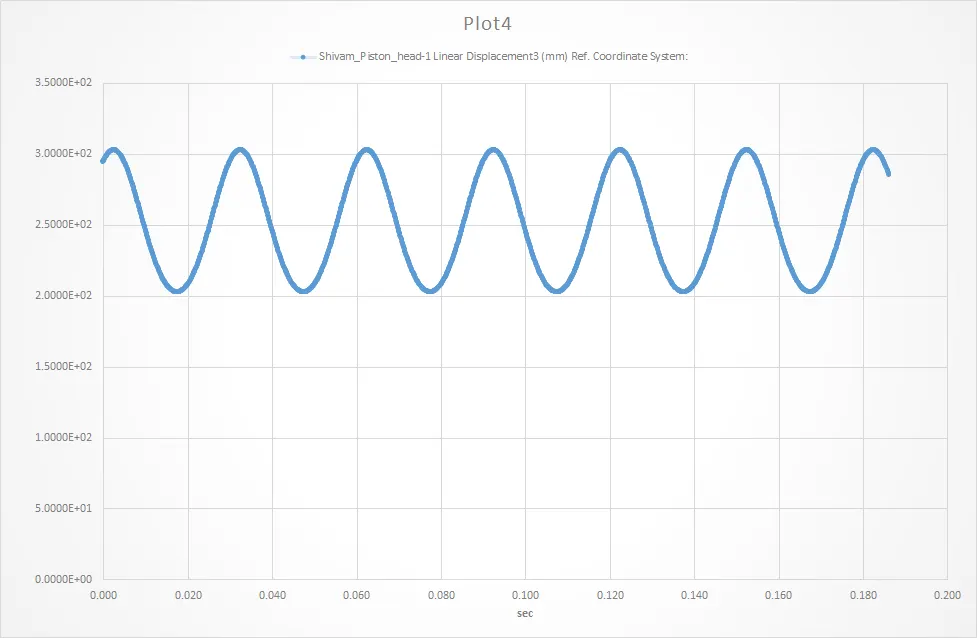
- A torque/motor was provided for the axis of crank with 2000 rpm in clockwise dirction. Solid body contacts were provided for different components with the material selected as Steel(Dry), Gravity was provided in the downward direction, precise contact and 12000 fps were provided as input for smooth transition and to obtain results more accurately and were solved by running calculations.
- Plot obtained for linear displacement of piston from results -
- Plot obtained for angular velocity of crank from results -
- Case 2 (10 mm Positive Offset) -
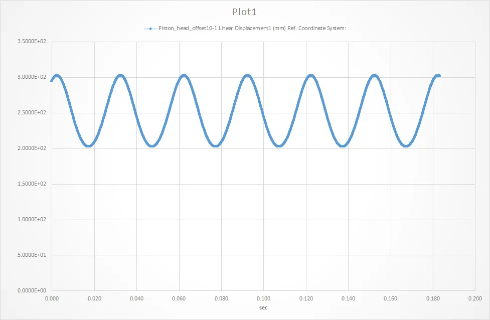
- A torque/motor was provided for the axis of crank with 2000 rpm in clockwise dirction. Solid body contacts were provided for different components with the material selected as Steel(Dry), Gravity was provided in the downward direction, precise contact and 12000 fps were provided as input for smooth transition and to obtain results more accurately and were solved by running calculations.
- Plot obtained for linear displacement of piston from results -
- Plot obtained for angular velocity of crank from results -
- Case 3 (10 mm Negative Offset) -
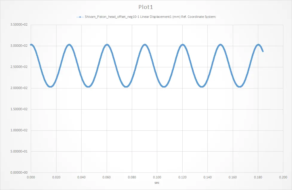
- A torque/motor was provided for the axis of crank with 2000 rpm in clockwise dirction. Solid body contacts were provided for different components with the material selected as Steel(Dry), Gravity was provided in the downward direction, precise contact and 12000 fps were provided as input for smooth transition and to obtain results more accurately and were solved by running calculations.
- Plot obtained for linear displacement of piston from results -
- Plot obtained for angular velocity of crank from results -
- Superimposing all these data in 1 chart:
CONCLUSIONS :
- The plot for linear displacement when the crank angle is at 0° or at time as 0 second, the piston is positioned at TDC and the displacement reaches the maximum value. After half of rotation (180°), the piston is at BDC and the displacement reaches minimum value and follows sinusoidal path. The angular velocity of crank almost remains constant throughout the motion.
- The amplitude for the plot with "0" mm Offset is 302.499 mm and is maximum as compared to 10 mm Positive Offset (302.3094 mm) and 10 mm Negative Offset (302.3090 mm) which is minimum,and is because there is reduction in the piston displacement which is due to the fact that the piston has to travel a less distance from TDC to BDC because of offsetting,
- Wrist pin offset refers to the piston wrist pin being a bit offset to one side of the piston i.e. for it to not be in the centre of the piston. When the piston pin is in the centre of the piston, now when the piston reaches top or bottom dead centre then, in this kind of setup the rod is straight up & down placing huge load on the rod. The crank has to rotate past TDC or BDC in order to get the piston moving again. This robs a lot of both power and RPMs from the engine. With an offset pin, the piston wrist pin is a little offset to one side of the piston therefore the rod is not straight up and down when the piston is at TDC or BDC. This in turn allows the crank to rotate with much less resistance giving the engine more power and speed. Having offset pin relieves the stress that is caused in the rod when it reaches top or bottom dead centre.
- Offsetting the cylinder axis from the crankshaft axis, minimizes rod angularity when cylinder pressure is at its highest. Reduced angularity leads to lower piston thrust forces, hence lower frictional losses during the period of maximum cylinder pressure, especially at the beginning of the power stroke when pressure rises sharply about 12-15 degrees after TDC.
- The 3D model, assembly, simulation of case 2 and case 3 can be found from the following Google drive link : Drive
- The link for the simulation of case 1 : Link for case 1