MBD Simulation on a Piston Assembly
AIM :
To create 3D model of different components of piston assembly and to run motion study analysis.
Cases:
| Sl.No |
Wrist Pin Offset |
Crank Speed (Rpm) |
|
1 |
"0" mm | 2000 |
| 2 | 10 mm Positive | 2000 |
| 3 | 10 mm Negative | 2000 |
"0" mm offset - if the crank rotation is in the clockwise direction.
"10" mm positive offset - If the crank rotation is in the clockwise direction.
"10" mm negative offset - If the crank rotation is in the clockwise direction.
Theory:
The piston’s function is to act as a moveable plug in the cylinder, forming the bottom part of the combustion chamber. There’s a gas-tight seal between the piston and the cylinder wall - so the only way for the hot combustion gases to expand is by forcing the piston down. It’s the same principle behind a cannonball, but instead of flying off into someone’s beloved pirate ship, the piston is pushed back up the cylinder by the rotating crankshaft and the cycle repeats itself.
Over 60% of the friction inside the engine comes from the motion of the piston assembly, and so this is a major area of focus for improving the efficiency of engines. The piston is still seeing ongoing development and research as we’ll see in more detail shortly.
Huge forces are generated during the change in direction of a piston on its up and down motion. A lighter piston assembly has less momentum, thus exerting less force and allowing higher RPM engines. This means that there’s a constant push to reduce the weight of the connecting rod and piston.
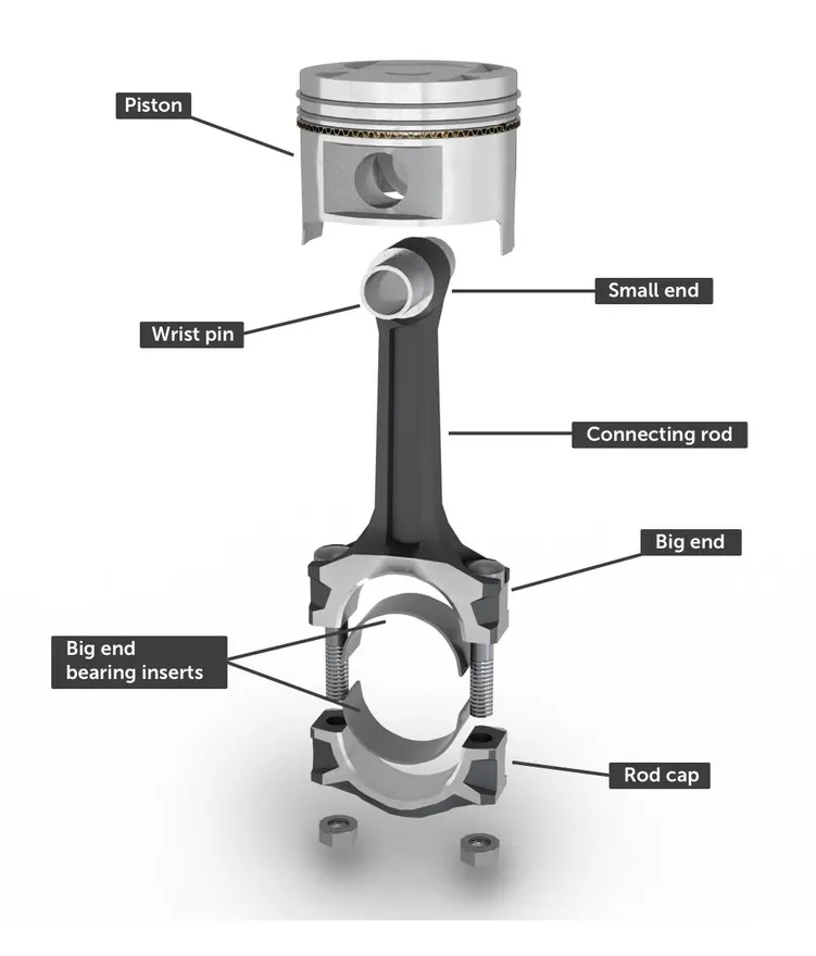
The piston is connected to the crankshaft through a connecting rod , often shortened to rod or conrod . These parts together are known as the piston assembly . Both ends of the connecting rod are free to pivot: The part of the connecting rod which connects to the piston is called the small end , and the end that attaches around the crankshaft is called the big end . The big end will have bearing inserts which minimise friction and maintain an exact oil clearance with the rod journal on the crankshaft. The connecting rod is split into two - with a rod cap being used to clamp around the big end bearing and crankshaft.
Design Procedure:
- Model 3D parts as per drawing.(Part file attached in zip)
- The components modelled are now assembled by importing into assembly. The first component inserted is made to float from being fixed. The temporary axes should be selected for the ease in the assembling. All the components are assembled with necessary constraints, so the desired motion can be achieved
- At first the crank shaft is inserted whose axis is made co-incident with the top and right plane and then its front plane is placed at some distance from the assembly's front plane . Then the connecting ros and the end cap are inserted and both of their axis are made coincident and then their faces are made coincident so that they move together.
- The axis of the crank is made coincident with the axis of the connecting rod. Then one side of the connecting rod is selected and the corresponding side of the crank is selected and made coincident with a distance mate of 1 mm to provide some clearance similarly piston head and wrist pin are inserted and made coincide along their respective axis and planes.
- The wrist pin axis and connecting rod axis rae made coincident and then the front plane of the connecting rod and the front plane of the piston head are made coincident. The right plane of the piston is made co incident with assembly right plane .
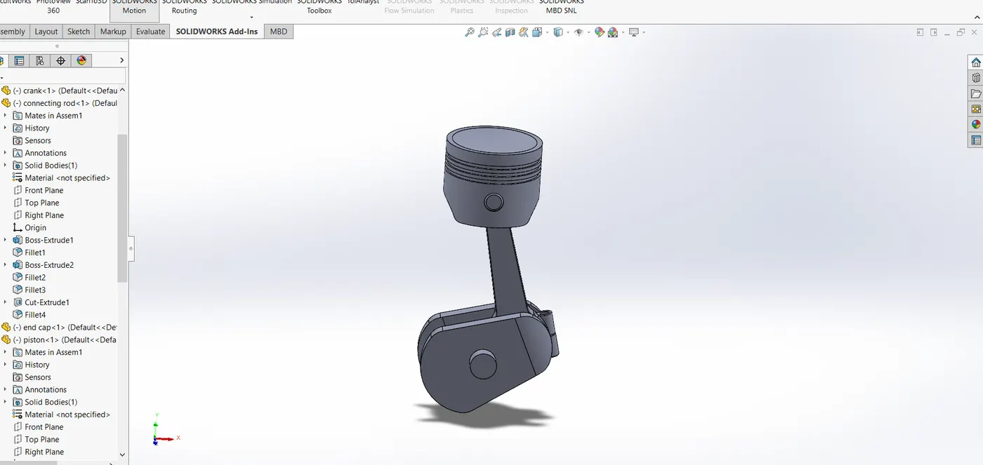
- Assembly file shown below.
Motion Analyses:
Case 1:
Omm offset
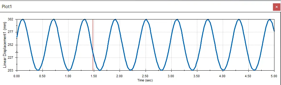
A torque/motor was provided for the axis of crank with 2000 rpm in clockwise direction. Solid body contacts were provided for different components with the material selected as steel(Dry) , Gravity was provided in the downward direction(Y-axis) precise contact and 1000 fps were provided as input for smooth and fast calculations.
Plot obtained for linear displacement of piston from results.
Case 2
10MM OFFSET
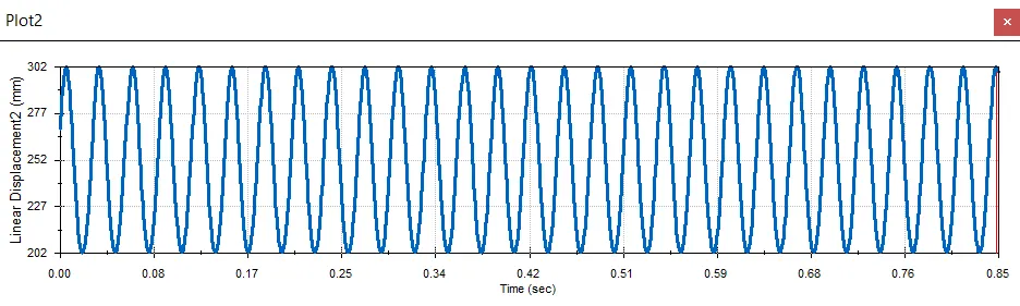
After providing 10mm offset with the crank, A torque/motor was provided for the axis of crank with 2000 rpm in clockwise direction. Solid body contacts were provided for different components with the material selected as steel(Dry), Gravity was provided in the downward direction(Y-axis) precise contact and 1000 fps were provided as input for smooth and fast calculations.
Negative Offset
Positive Offset:
Conclusion:
- Offsetting the cylinder axis from the crankshaft axis minimizes the rod angularity when cylinder pressure is at its highest. Reduced angularity leads to lower piston thrust forces hence lower frictional losses during the period of maximum cylinder pressure.
- Piston displacement is observed less due to low travel of piston fron TDC to BDC.
Youtube Link: